
Lithium batteries: current technologies and future trends
Abstract:
This chapter reviews lithium battery science and technology from the early development of lithium batteries to potential future developments. The chapter first discusses the history of the batteries outlining the initial evolution of primary and secondary systems. The chapter then reports on the characteristics of lithium-ion batteries with particular attention focused on the safety and energy aspects. The chapter continues by illustrating the expected progress in terms of new, superhigh energy density batteries. The chapter closes with considerations on global lithium resources.
18.1 Introduction
Global warming is one of the most serious threats in today’s society. The ongoing growth of CO2 emissions, the result an energy policy still based principally on the burning of fossil fuels, is currently a source of major concern. The efficient use of renewable energy sources and the replacement of internal combustion engines with electric motors for the development of sustainable vehicles, such as hybrid vehicles (HEVs), plug-in hybrid vehicles (PHEVs) and ultimately, completely electric vehicles (EVs), are therefore crucial aims for our society.
However, alternative, green energy sources, such as solar and wind power, are intermittent; efficient use of these sources thus requires storage systems to compensate. Similarly, HEVs, PHEVs and EVs require an on-board energy source to power the electric engine. Of the various possible choices, the most suitable have been found to be rechargeable electrochemical batteries, that is, portable devices capable of delivering the stored chemical energy as electrical energy with high conversion efficiency and with no gaseous emissions. Moreover, batteries offer the most promising option for powering HEVs or EVs efficiently. Lithium batteries are particularly appealing in this respect, due to the intrinsic high value of energy density.
When they were first developed, these batteries used a lithium metal as anode, hence the name lithium batteries.1 Due to its electrochemical equivalent, the highest of all metals, lithium can in principle assure high specific capacity, that is, 3860 Ahkg−1. Obviously, lithium metal is not compatible with water and its use necessitated a move from common aqueous electrolytes to more electrochemically stable organic electrolytes, generally formed by a solution of lithium salt in a carbonate organic solvent (e.g., propylene carbonate, ethylene carbonate) or in a mixture of these. The first, important success of lithium batteries was in the medical field, specifically in cardiac pacemakers.
In the early stages, pacemakers had to rely on the only battery available at the time, namely the primary zinc-mercury oxide battery. To provide the energy required for correct operation, two Zn-HgO batteries in series were needed; these occupied almost three-quarters of the size of the device, thus greatly affecting its weight and volume. In addition, the two zinc-mercury oxide batteries had only a 2-year lifespan, entailing a new operation to replace them and causing major stress to the patient. The breakthrough arrived with the development of the lithium-iodine battery, obtained by combining a lithium metal anode with an iodine-based cathode separated by a lithium iodide solid electrolyte2 that offered a practical energy density of about 250 Wh kg−1, almost five times higher than that of the zinc-mercury oxide. The development of the lithium-iodine battery had a tremendous impact on the efficiency and lifespan of the pacemaker, and, consequently, on patient comfort, since its use resulted in significant reduction in weight and volume. It also greatly improved the operational life of the pacemaker, extending it to 6–7 years. Indeed, even today almost all implanted pacemakers are powered by the lithium-iodine battery.
In their initial stage of development, lithium batteries were of the primary type. However, their success in the medical field, as well as in the market of portable, consumable electronics, increased the interest in moving to secondary, rechargeable systems. In theory, this transition should not have been difficult to achieve: lithium ions formed in discharge were expected to plate back into the lithium metal in charge, this ensuring the cycling of the system. Although this was then proved to be not true (as discussed later), attention was initially focused on the cathode side with the aim of identifying materials that could withstand a long cycle life. The breakthrough was obtained in 1978 with the development of the so-called insertion or intercalation electrodes,3 that is, of compounds that can reversibly accept and release lithium ions in and out of their open structure. To allow the continuation of the electrochemical reaction, as well as of the cycle life, the material must ensure a reversible evolution of both the electronic structure (to balance the positive charge of the inserted lithium ions) and of the crystal structure (to prevent the lattice collapsing). These requirements can be met by transition metal compounds such as titanium sulfide, TiS2, which can exchange lithium ions in and out of its layered structure, accompanied by a change in the valence state from IV to III. Figure 18.1 illustrates the process of lithium intercalation in titanium disulfide. The process can be run electrochemically using a cell such as that schematized on Fig. 18.1a. The cell contains a Li metal anode and a TiS2 cathode separated by a lithium-conducting electrolyte such as a solution of a lithium salt (e.g., LiPF6) in an organic solvent mixture (e.g., ethylene carbonate-dimethyl carbonate, EC-DMC mixture). The overall process of the cell is xLi + TiS2 → LixTiS2, where x is the degree of intercalation. The insertion of lithium ions is accompanied by an electronic evolution of the hosting material. Figure 18.1b shows the energy band diagram of the intercalation electrode (TiS2) and of the counter-electrode (Li) in the Li/TiS2 electrochemical cell. The potential of this cell E is given by the difference between the Fermi level of lithium EFLi and the Fermi level of TiS2, EFTiS2. When the external circuit is closed, electrons pass from lithium to the titanium disulfide, where they fill the wide anti-bonding band, which has a large density of free states. During the process, the Fermi level of the metal decreases while that of the dichalcogenide increases; the cell potential thus progressively decreases over the course of the electrochemical process.
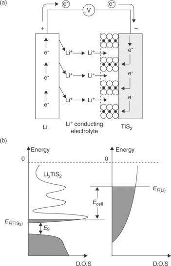
18.1 Mechanism of the intercalation process of lithium in titanium disulfide in terms of electrochemical cell operation (a) and evolution of band diagrams (b).
The first commercial rechargeable lithium batteries appeared in the late 1970s to early 1980s, one manufactured by the Exxon Company in the USA with a TiS2 cathode and another by Moli Energy in Canada with a MoS2 cathode, both using liquid organic electrolytes. However, some unexpected faults and incidents led to the rapid conclusion that there were operational problems preventing the safe operation of these batteries over a long period of time. It was soon discovered that these were associated with the anode: due to its very high reactivity, lithium metal easily reacts with the electrolyte with the formation of a passivation layer on its surface. The layer, usually called the solid electrolyte interface (SEI),4 is permeable to lithium ions, thus allowing the discharge process to continue; however, irregularities on the surface of the SEI may lead to uneven lithium deposition upon charge, with dendrite formation eventually causing the cell to short. In extreme cases, these uncontrolled events may give rise to overheating effects with thermal runaway and explosions, resulting in serious safety hazards, as shown in Fig. 18.2.
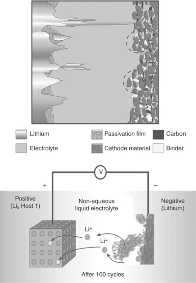
18.2 Scheme and image of a lithium dendrite growing across a lithium cell. (Source: Ref. # 17, with the permission of the Nature Publishing Group.)
To ensure that the cells behaved as desired, two options had to be considered: (i) a careful choice of the electrolyte system in order to ensure optimized, smooth lithium deposition or (ii) the replacement of the lithium metal with a less aggressive anode material. The feasibility of the first option was demonstrated by Armand in 1978 who originally proposed the use of a solvent-free, solid-state, polymer electrolyte, formed by a complex between a lithium salt (e.g., lithium triflate) and a coordinating polymer (e.g., poly ethylene, oxide, PEO) and demonstrated its efficient use in a rechargeable lithium polymer battery.5,6 This concept was later used to produce a large size, laminated battery module based on a lithium foil anode, a PEO-based electrolyte and a vanadium oxide cathode.
However, despite this and other successful demonstration projects, the lithium polymer battery has never been commercially produced on a large scale, mainly due to concerns about the lithium metal electrode, since the risks associated with its operation were never fully overcome. Clearly, the second option was required for the development of the rechargeable lithium battery: the lithium metal had to be replaced with another more reliable electrode. The winning approach was the use of an insertion electrode at the anode side as well, in order to develop a totally new concept battery that exploited the combination of two insertion electrodes, one capable of accepting lithium ions, operating as the anode, and the other, capable of releasing lithium ions, operating as the cathode. During charge, the negative intercalation electrode acts as a ‘lithium sink’ and the positive one as the ‘lithium source’ and the overall electrochemical process of the cell involves the transfer of x equivalents of lithium ions between the two intercalation electrodes; the process is then reversed upon discharge and cyclically repeated. These systems are actually concentration cells in which lithium ions ‘rock’ across the electrodes, creating a new type of system, originally called the lithium rocking chair battery.
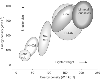
In fact, the concept of a rocking chair battery dates back to the late 1970s7,8 and was experimentally demonstrated in the early 1980s.9–12 However, more than 10 years passed before the concept could be practically implemented in a battery launched by the Japanese manufacturer Sony in 1991.13 In this first commercial battery, graphite was used as the ‘lithium sink’ anode and lithium cobalt oxide as the ‘lithium source’ cathode. The role of the cathode is particularly important in this system: it must be capable of providing the lithium ions to ensure that the electrochemical process functions correctly, as well as accepting them back in a reversible manner to ensure the cycling life of the battery. These characteristics were provided by LiCoO2, a material invented by Goodenough in 1980.14 Without this fundamental discovery, the success of the rocking chair battery could never have been achieved. Although other cathode materials have been developed over time, most of the commercial production of lithium rocking chair batteries still relies on lithium cobalt oxide as cathode. The success of these batteries, renamed ‘lithium-ion batteries’ by Sony, triggered interest worldwide and they are currently produced at the rate of several billion units per year by various manufacturers, mainly located in Asia. The success of the lithium-ion batteries is indeed outstanding. Due to their specific properties, mainly in terms of energy density, which largely surpass those of conventional nickel-cadmium and also of newer systems such as the nickel-metal hydride battery (see Fig. 18.3), lithium-ion batteries are today the power sources of choice for a series of very popular portable devices, such as cellular phones, notebooks, camcorders, Mp3 players and others.15
18.2 Lithium-ion batteries
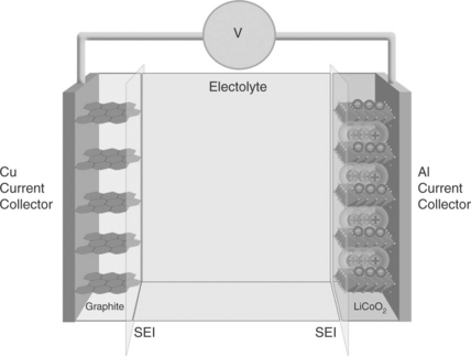
As mentioned in the previous paragraph, in its most conventional structure, a lithium-ion battery contains a graphite anode (e.g., MCMB), a cathode formed by a lithium metal oxide cathode (e.g., LiCoO2) and an electrolyte consisting of a solution of a lithium salt (e.g., LiPF6) in a mixed organic solvent (e.g., ethylene carbonate-dimethyl carbonate, EC-DMC) embedded in a separator felt.16,17
Figure 18.4 schematizes the battery. At first sight, the electrochemical process that drives this battery appears quite simple, as it consists of the reversible exchange of lithium ions between the two electrodes:
with a concomitant removal and addition of electrons. However, key side processes must occur to ensure that the process is successful. As schematically shown in Fig. 18.5, both the graphite and the lithium cobalt oxide electrodes operate outside the electrochemical stability window of the common LiPF6-EC-DMC electrolytes, for example, LiPF6 in ethylene-diethylene carbonate, EC-DMC, mixture. Thus, the C/LiCoO2 battery is in principle thermodynamically unreasonable; however, the graphite anode and the lithium cobalt oxide cathode can operate since the initial decomposition of the electrolyte results in the formation of a SEI passivating film on their surface, providing the kinetic stability that allows the repetition of the charge and discharge processes. From Fig. 18.5a, which illustrates the operational principle of the film formation, it may be observed that the deposition of the protective SEI film involves an initial consumption of charge accompanied by gas evolution and a loss of the battery capacity (initial irreversible capacity), as shown in Fig. 18.5b. Both these events are of key importance, since they may determine the selection of new electrode materials, as well as affecting the overall safety of the battery (see below).
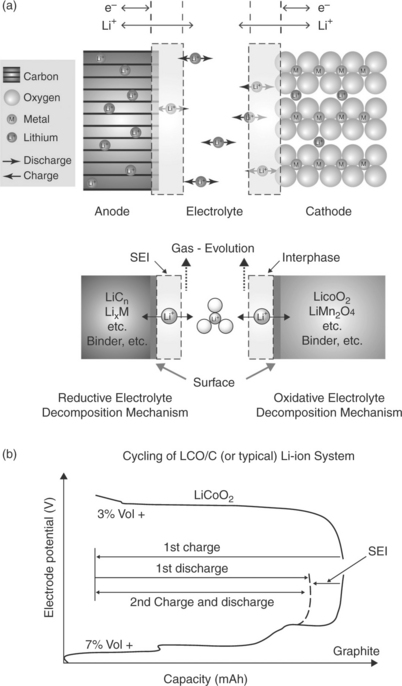
18.5 Operational principle of (a) SEI formation and (b) the associated initial loss of capacity in a C-LiCoO2 lithium-ion battery. (Source: Taken from Report of the Basic Energy Sciences Workshop on Electrical Energy Storage, DOE, July 2007.)
Due to the high value of energy density, that is, 150 Whkg−1 and 650 Whl−1,16,17 which exceeds that of any competing technology by a factor of at least 2.5, lithium-ion batteries dominate the portable electronic market and are rapidly growing in importance in both the power tool equipment market and especially in the emerging sustainable vehicle market.18 However, current Li-ion batteries, although commercially produced, have not yet reached a technological level sufficient for the requirements of efficient hybrid or EVs. Reduced costs, improved safety and increased energy density are all essential for the use of these batteries in the efficient HEVs and EVs.
18.3 Safety of lithium-ion batteries
At extreme operational conditions, such as at the upper limit of the charge process, oxygen may be released from the layered LiCoO2 cathode and, in the event of local overheating, may react with the flammable organic liquid electrolyte, giving rise to thermal runaway effects, and even in some cases to explosions. Various fire incidents have been reported both during the manufacture of the battery and in battery-operated devices. These incidents are very limited in number compared to the number of a cells produced (a few hundred cases versus billions of cells per year) and have therefore not had a significant impact on the consumer electronic market; however, they cannot be tolerated in the vehicle market: a fire in a battery-powered car would be extremely harmful, if not fatal, to the success of the entire electric transportation business. Hence, Li-ion batteries intended for use in HEVs or EVs must fully meet all safety requirements. This is not an easy task. The substitution of LiCoO2 with a chemically more stable material, for example, olivine LiFePO4 (the PO4 group has stronger covalent bonds than the CoO2 group) is not a long-term solution, due to the reactivity of the other components and in particular of the liquid organic electrolyte. Consequently, a great deal of attention is currently focused on investigating electrolyte systems that are more reliable and stable than the liquid organic carbonate solutions used at present.
Solutions of lithium salts in ionic liquids have been shown to be particularly promising in this respect. Ionic liquids (ILs) are room-temperature molten salts formed by the combination of large organic cations (e.g., imidazolium or pyrrolodinium cations) and highly charge-delocalized anions (e.g., N,N-bis(trifluoromethane)sulfonimide (TFSI) anion), as shown in Fig. 18.6. ILs are characterized by many favourable features, including high conductivity, environmental compatibility and particularly high thermal stability.19 In contrast to organic carbonate solutions, which catch fire very easily, IL-based solutions are not flammable and are generally stable up to 300–400°C. In addition, ILs are basically composed of organic ions which may undergo almost unlimited structural variations, thanks to the ease with which a large variety of their components can be prepared: this provides a unique source of materials that can be ad hoc designed and selected to fulfil the requests of any device.20 In light of these features, ILs are in principle very appealing and safe lithium-ion battery electrolytes.
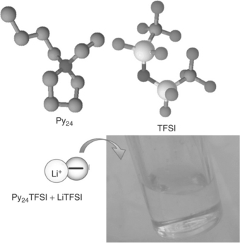
18.6 Ionic liquids are room temperature molten salts formed by the combination of weakly interacting large cation, for example of a pyrrolidinium type, and a flexible anion, for example N,N-bis (trifluoromethane sulfonyl) imide, TFSI. (Source: Ref. # 66, with the permission of the Royal Society of Chemistry (RSC) Publishing Group.)
ILs are currently undergoing testing in many industrial and academic laboratories with the aim of establishing their practical feasibility.21–24 It has recently been shown that ILs can be efficiently trapped within polymer matrices to form membranes combining the thermal stability of the IL with the plastic nature of the polymer.25 Figure 18.7 shows a view of one typical example of these membranes.
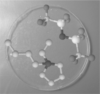
18.7 Picture of a lithium-conducting IL-based membrane formed by trapping Py24TFSI + LiTFSI in a PVdF polymer matrix. (Source: Ref. # 25, with the permission of the Wiley Publishing Group.)
However, despite these initial successes, a great deal of work is still needed before IL-based systems can be successfully and fully implemented as practical lithium-ion battery electrolytes. Many basic aspects are in need of further clarification. For instance, the structure of the IL/electrode interface, which is of key importance for battery applications, remains unclear. In addition, IL-based electrolytes are apparently not stable at low, reducing voltages, for example, when in contact with highly negative electrodes, such as lithium metal and/or graphite anodes. The question of whether this instability should be associated with the reduction of liable groups in the IL cation’s structure and/or, more simply, to the actions of residual impurities, is yet to be resolved. Therefore, there is an urgent need to devote more attention to these issues by carrying out a series of systematic studies on the fundamental processes that occur at the solid electrode-ionic liquid interface. Both experimental and theoretical approaches may be able to shed some light on the basic electrochemistry of ionic liquids.
18.4 Energy density of lithium-ion batteries
Another key requirement for ensuring that the use of Li-ion batteries in EVs is profitable is an increase in energy density. It may be estimated that in order to achieve a range of 150 km with a single charge for a common, sub-compact passenger car, based on the Li-ion technology currently available, a battery with 150 Whkg−1 would weigh over 150 kg, which would exceed any practically acceptable limit. Clearly, advanced batteries, with levels of energy density two or three times higher than those offered by conventional systems, are urgently needed. The achievement of this goal requires the development of electrode materials with a much higher specificity capacity than the conventionally-used materials, while still maintaining the same voltage levels.
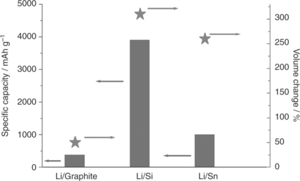
With this in mind, much attention is currently devoted to tin and silicon anodes, since they are abundant (cheap), environmentally harmless and, most importantly, their alloys with lithium - that is, Li4.4Sn and Li4.4Si - offer specific capacity values much higher than conventional graphite, namely 990 and 4200 mAhg−1, respectively, versus 370 mAhg−1. The potential offered by these materials has been known for some time;26,27 however, until recently this potential could not be exploited due to a serious issue associated with the large volume expansion-contraction changes experienced during the lithium alloying-dealloying electrochemical process. This in turn induces cracks and eventually, pulverization of the electrode, finally causing it to die after only a few cycles. The advent of nanotechnology has helped to control this issue. In fact, by reducing the metal particle size to a nanometric level, the volume change may be controlled and the lithium diffusion length greatly reduced, improving the performance of the electrode in terms of both life and rate capability.28,29 Nanostructured electrodes, however, have a very large surface area, which is reflected in their high reactivity and low tap density, with an associated increase in safety hazards and a decrease in volumetric energy density.
The breakthrough in the lithium-metal alloy field has been achieved through the development of cleverly designed carbon-metal composites. In very simple terms, these composites may be described as being formed by low-size metal particles dispersed within a carbon matrix. The carbon matrix, while maintaining in its core the nanosized metal particle configuration that helps to contain the volume stress, supplies an overall compact shell structure that ensures stability and provides high tap density.
The validity of this concept is confirmed by practical examples. One is given by the tin-carbon, Sn-C composite,30 whose morphology is shown by the TEM images given in Fig. 18.8, which clearly show that the tin particles are kept at a nanosize dimension (about 10–30 nm) and that they are evenly dispersed within the carbon matrix. The latter has a two-fold, beneficial action: namely, it provides enough free volume to accommodate the expansion-contraction of the tin, this ensuring cycling stability, and, at the same time, it acts as a protective shell, ensuring the safe handling of the electrode powder. In addition, in situ XRD analysis demonstrates that the electrochemical lithium alloying-dealloying process is fully reversible.31 Obviously, the delivered specific capacity of the Sn-C is lower than that of pure tin, namely about 500 versus 990 mAhg−1, due to the weight contribution from the carbon matrix, if this is 50% as in the case of the Sn-C composite shown in Fig. 18.8.30 This disadvantage in terms of capacity is, however, largely counterbalanced by the excellent electrochemical response of the composite. Indeed, it has been demonstrated that a capacity of about 500 mAhg−1 can remain stable for several cycles.30 It should be noted that this capacity level is still much higher than that obtainable by the conventional graphite anode.
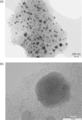
18.8 TEM images of the Sn-C composite. The images clearly show that the tin particles are kept at nanosize dimensions, that is, about 10–30 nm (b) and that they are evenly dispersed within the carbon matrix (a). The latter has a two fold, critical action, namely it provides enough free volume to accommodate the tin’s expansion-contraction, this ensuring cycling stability, and, at the same time, acts as a protecting shell. (Source: Ref. # 30, with the permission of the Wiley Publishing Group.)
The interest in Li-Si alloys is even greater than that in Li-Sn alloys; this is to be expected given that the former offers the highest theoretical specific capacity so far observed for any lithium battery electrode material. The volume stress issue, already discussed for tin, also holds for silicon, possibly even to a greater extent. Indeed, the volume change expected for silicon upon full alloying with lithium to form the Li4.4Si phase is of the order of 300% while that for tin at the same Li44Sn composition is about 250%, as shown in Fig. 18.9. Therefore, as with tin, extensive work has been devoted in the last few years to the design of electrode configurations capable of buffering the volume changes in order to make the silicon electrode viable for practical applications as well. Morphological modifications aimed at the development of nanometric structures, such as nanosized particles,32 submicrometric pillars33 and nanowires,34 led only to limited improvement in terms of cycle life. Beside, some of these morphologies, for example, silicon nanowires, are dangerous to human health.35 Moderate advances have been made by using methyl cellulose CMC as the selected binder for the Si electrode blend36 and by exploiting three-dimensional (3D) porous Si particle configuration;37 however, the cycling response and the tap density of these electrodes are both low, resulting in a limited life and modest volumetric energy density, respectively.
As in the case of tin, for silicon the real breakthrough again relies on the development of appropriate carbon composites. An effective approach is to move to spherical silicon-graphite-carbon morphologies, formed by nano size Si particles surrounded by amorphous carbon in a hollow spherical morphology, as shown in Fig. 18.10. Similarly to the case of the tin-carbon composites, the carbon matrix acts as a buffering agent to compensate for the mechanical stress associated with the volume changes experienced by the Si electrode upon lithiation-delithiation. Indeed, it has been proven that this particular morphology is quite effective in providing excellent electrochemical performance.38
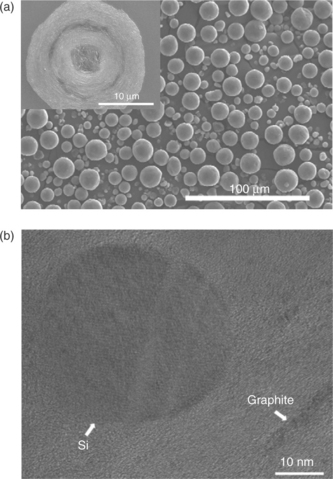
18.10 SEM (a) and TEM (b) images of a spherical of Si-C composite. (Source: Reference 38, with the permission of the Elsevier Publishing Group.)
The results reported for both tin and silicon confirm that moving to a composite configuration is the correct approach to allow the related lithium alloy electrodes to be produced on a commercial scale. The search for high-capacity lithium metal alloy anodes may be considered successfully completed and it can be assumed that these high-capacity anodes may soon be used in practical applications. An example is provided by the Sn-C-Co ternary composite that is currently used by a Japanese manufacturer to produce a battery that goes under the commercial name of Nexelion.39,40
The search for innovative electrodes capable of offering improvements in the lithium-ion battery technology has been also extended to the cathode side. A great deal of attention is today focused on the olivine-type LiMPO4 (M = Fe, Mn, Co and Ni) family: compounds of this type offer high thermal stability, superior safety properties, and an excellent cycle life. They are also low cost, non-toxic and environmentally friendly. Consequently olivines, originally developed by Goodenough,41 are proving to be promising alternative cathode materials, particularly for large-scale batteries designed for applications in EVs or in renewable energy storage plants.42–44 However, LiMPO4 materials have an intrinsically poor electrical and ionic conductivity, which affects their electrochemical performance. In the case of M = Fe, that is, of LiFePO4, the poor conductivity issue has been successfully overcome by synthesizing the compound in the form of nanosized particles coated by a thin conductive carbon layer.45–51 A typical morphology of these C-coated LiFePO4 particles is shown in Fig. 18.11.
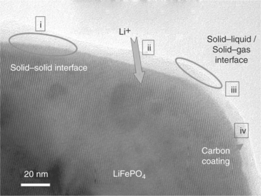
18.11 A common modification of the LiFePO4 electrode morphology involves surface carbon coating, in order to enhance the electronic conductivity and thus allow the ongoing of electrochemical process with full capacity delivery. (Source: Taken from Report of the Basic Energy Sciences Workshop on Electrical Energy Storage, DOE, July 2007.)
The carbon-coated, nanoscale LiFePO4 electrode has demonstrated more than 90% of its theoretical capacity and an excellent rate capability; hence, LiFePO4 has come to be considered as one of the most promising cathode materials for second-generation lithium-ion batteries.
The interest in olivine electrodes, already established by the success of LiFePO4, may be increased by a move to considering the manganese member of the family, LiMnPO4, since the Mn2 +/Mn3 + redox potential is higher than that of the Fe2 +/Fe3 + redox potential, namely 4.1 V versus Li/Li+ compared to 3.4 V versus Li/Li+. However, LiMnPO4 also suffers from poor electrochemical performance, especially at high current densities, because of its inherently low electronic and ionic conductivity caused by heavy polaronic holes localized on the Mn3+ sites and by the strain at the mismatched LiMnPO4/MnPO4 two-phase interface.52–55 To enhance the rate capability of LiMnPO4, approaches similar to those applied to LiFePO4 have been undertaken, including: (i) reduction of the particles to a nanosize dimension, with a significant reduction in the Li+ diffusion path and an increase in the area of contact with the electrolyte; and (ii) application of a thin carbon coating layer on the surface of the particles.56–62
Although nanosized LiMnPO4 has demonstrated high gravimetric capacity (92% of the theoretical value) and improvement in rate capability, its tap density is very low compared to conventional oxide electrode materials. As already observed, low tap density results in low volumetric energy density and, consequently, nano-LiMnPO4 cathodes are not suitable for lithiumion batteries designed for applications in PHEVs or EVs. In addition, the extended contact area between the large surface area nanosized particles and the electrolyte leads to undesirable reactions and poor thermal stability, resulting in poor cycling performance and safety hazards.
From this perspective, a micro-sized, spherical LiMnPO4 morphology is expected to provide a step forward by providing high tap density, and hence high volumetric capacity. On the other hand, micro-sized particles are generally affected by a long Li+ ion diffusion path, which results in a poor rate capability. The challenge here is to obtain micro-sized LiMnPO4 powders that may offer high tap density combined with good rate capability. A recent success in this regard has been achieved through the development of Mn-Fe mixed compounds with a LiMn1–xFexPO4 composition; these combine good electrochemical performance in terms of cycling and rate capability with high tap density.63 Although very popular, olivine compounds cannot lead to significant enhancements in energy density; consequently, other cathode materials are currently being considered. One interesting example is provided by Li[Ni0.45Co0.1Mn1.45]O4 (LNMO), a spinel material characterized by an electrochemical process evolving with a high voltage plateau. When prepared in suitable morphology, this electrode is capable of operating with high rates and long cycle life and may accordingly be used as the cathode for advanced lithium-ion batteries. It has been recently demonstrated that by combining LNMO with a Sn-C composite64 or with a Li4Ti5O12 (LTO)65 anode, new types of batteries providing energy density in the order of 180 Whkg−1 can be obtained.
18.5 Future trends
18.5.1 Lithium–sulfur and lithium–air superbatteries
Increases in the achievable energy density from the present 150–200 Whkg−1 may contribute to the development of the EV market; however, no method has yet been found for decreasing the weight of the batteries to an acceptable level for powering an EV expected to drive for 150 km with a single charge. Other solutions must therefore be sought. In particular, the intercalation chemistry commonly used in the Li-ion battery technology must be abandoned in favour of alternative chemistries. Intercalation-type electrodes may accept a maximum of one lithium ion equivalent per mole of the host compound, which necessarily limits their specific capacity. It is now clear that new approaches must be considered in order to enhance energy density.66 One possible approach is to pass from intercalation to conversion chemistry, namely to light elements characterized by electrochemical processes that can ensure the exchange of many more lithium ions and, thus, to offer specific capacities that are higher by several orders of magnitude.
A very promising system of this type is provided by the lithium-sulfur, Li-S cell, operating with a two-electron electrochemical process: 2Li + S → Li2S, which is associated with a specific capacity of 1675 mAhg−1(S) and a working voltage of about 2.1 V, which leads to a theoretical energy density of 3500 Whkg−1, that is, almost one order of magnitude higher than that of conventional, intercalation chemistry-based Li-ion batteries. The concept of this battery is not new. However, the effective development of this highenergy system has so far been prevented by a series of unresolved issues. One major issue is associated with the solubility of the cell discharge products in lithium-ion organic carbonate electrolytes - namely polysulfides LixSy – that eventually diffuse all the way to the lithium anode causing severe corrosion effects.67,68
All these events result in the loss of active materials, low utilization of the sulfur cathode, low overall coulombic efficiency and ultimately in severe capacity decay upon cycling. Another basic issue is the low electronic conductivity of S, Li2S and of the intermediate Li–S products, which severely affects the rate capability of the battery. A final problem, often overlooked, is the use of lithium metal as the preferred anode; this is known to cause serious safety risks due to the uneven deposition upon charge, which may result in the cell shorting, with associated thermal runaway and, eventually, fires or explosions.
These obstacles have led to limited interest in lithium/sulfur batteries. However, in recent years the system has once again become the focus of attention due to a series of important technological breakthroughs. Some advances have been made by fabricating nanostructured sulfur electrodes based on either (i) a mixture of sulfur and mesoporous carbon69 or (ii) sulfur-carbon spherule composites,70–72 or by developing polysulfide reservoirs based on porous silica embedded within the carbon composite.73 All these proved to be successful approaches for improving the conductivity of the electrode, as well as for controlling the solubility of the discharge products.
Further progress was achieved by changing the cathode from the common sulfur-carbon composite to a lithium sulfide-carbon composite.74–76 In this way the cathode becomes the lithium-ion source allowing the replacement of the reactive lithium metal with a different and more reliable lithium-accepting material, thus obtaining a metal-free lithium-ion sulfur battery. This concept was first demonstrated by using a tin-carbon anode74 and further confirmed with a silicon-carbon anode.77
These results all contributed to the upgrade of the lithium/sulfur battery technology; however, some issues still remain that prevent the full practical exploitation of this high-energy battery system. Most recent studies rely on a conventional liquid organic carbonate solution as the preferred electrolyte: although the sulfur and/or the lithium sulfide are shielded into a carbon matrix, either mesoporous69 or spherical71,72 which should in principle prevent direct contact with the electrolyte, it has not yet been established whether the issue of the solubility of the polysulfides is wholly resolved.
Advances may be possible if conventional liquid electrolytes are replaced by gel-type electrolyte membranes of suitable composition. One example of this would be a membrane formed by trapping a lithium conducting organic solution, added by a dispersed ceramic filler, in a poly(ethylene oxide)–lithium trifluoromethanesulfonate, PEO-LiCF3SO3, matrix. This composite electrolyte may be described simply as a membrane consisting of liquid zones contained within a polymer envelope. It is assumed that the polymer shell acts as a physical barrier to prevent the polysulfide cathode products from coming into contact with the internal liquid solutions. Experimental results have indeed confirmed the validity of this approach.74,76 Plate VI (see colour section between pages 238 and 239) illustrates a scheme of and a photographic image (Fig. 18.12a) of Sn-C/Li2S polymer battery and its theoretical value of energy density in comparison with that of the conventional Li-ion battery technology (Fig. 18.12b).
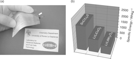
18.12 (a) Image of the Sn-C/Li2S polymer battery. (b) Energy density values in comparison with conventional lithium-ion technology are shown. (Source: Reference 74, with the permission of the Wiley Publishing Group.)
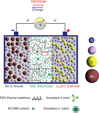
Plate VI Scheme of the Sn-C/Li2S polymer battery. With the permission of John Wiley and Sons (Wiley) Publishing Group.
An even more effective means of blocking the dissolution of the reaction products is expected to be provided by the use of totally solvent-free, solid-state, lithium-conducting membranes, such as those formed by poly(ethylene oxide), PEO-lithium salt complexes.78 These membranes have been effectively tested as separators in lithium-sulfur cells by Jeong et al.79 and more recently by Hassoun and Scrosati.80 The results are quite encouraging, demonstrating that full capacity can be obtained by solid-state, PEO-based polymer Li/S-C batteries. One issue is that these polymer electrolyte batteries have to operate at around 70–90°C, namely in the temperature range where the conductivity of the solid-state membranes reaches useful values. However, this is not a significant disadvantage in applications where operation at moderately high temperatures can be tolerated, such as in the EV field.
Oxygen is in principle even more promising than sulfur as a cathode material. Its use may lead to the development of lithium-air batteries with a theoretical energy density value reported to be as high as that provided by gasoline, although this value is unproven. The most commonly adopted method to estimate the capacity of the lithium-air battery is to base it on the mass of the electrode, either carbon, catalyst or both. However, this option has caused some concern, since it is dependent on the electrode surface and oxygen flux, which are not easily reproducible as they pass from one cell to another.
The astonishingly high energy value of the lithium-air battery, which is greater than that of any known battery, is the cause of the substantial world-wide interest in the technology, leading it to be considered the ‘holy grail of batteries’. Accordingly, research into lithium-air batteries is heavily funded in a number of countries and a large number of academic and industrial laboratories are involved in developing the technology. However, so far no truly convincing evidence of the effective practical relevance of the battery has been reported. Major problems, ranging from the reactivity of the lithium anode to the poor reversibility and efficiency of the oxygen electrode, have restricted the performance of lithium-air battery prototypes to a few charge–discharge cycles and to a low rate capability.
Two approaches are principally employed in the development of lithium-air batteries, which differ in the type of electrolyte used, see Fig. 18.13. In the first, an aqueous electrolyte is used in combination with a lithium metal electrode protected by a water-repulsive Li + conductive glass-ceramic of the Nasicon type81–83 or by an anion exchange membrane84 (Fig. 18.13a). The overall electrochemical process of this cell configuration is O2 + 4Li + 2H2O → 4LiOH, which is associated with an estimated energy density of the order of 5000 Whkg−1. This lithium-air aqueous battery operates best in the primary mode. The remaining issues to be resolved before the technology can be practically exploited to the full are the mechanical instability of the protecting film, its high interfacial resistance and the solubility of the reaction products.
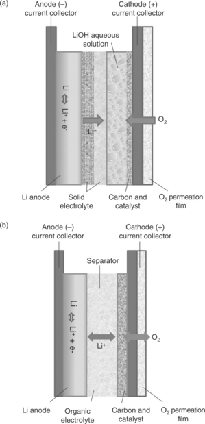
18.13 The two versions of the lithium-air battery differing by the type of electrolyte. (a) Aqueous electrolyte, protected lithium anode; (b) non-aqueous electrolyte, unprotected lithium anode.
In the second approach, an unprotected lithium metal anode is used, together with a separator embedded by a non-aqueous electrolyte and a carbon-supported air cathode, with or without a catalyst.85,86 (Fig. 18.13b). This is the most appealing and most widely researched option, since the basic process 2Li + O. → Li2O2 provides the highest theoretical energy density. Although the practical values are obviously affected by the weight of the ancillary battery components, for example air compressor and flowing control, the energy expectations for the non-aqueous electrolyte lithium-air battery remain very high. Unfortunately, the implementation of this system is compromised by a number of issues that are more serious than those discussed earlier for the aqueous option. A major problem is sensitivity to moisture: even traces of water must be avoided, as if these come into contact with the lithium metal electrode, the reliability, safety and cycle life of the battery can be seriously affected. In open systems this requires the addition of an air scrubbing apparatus. As an alternative, cathode-protected designs, which make use of a water-blocking membrane, can be used. Obviously, these modifications may affect the performance of the battery in terms of cost and energy density (weight of the additional ancillary parts), as well as rate capability (large iR drop due to the limited ionic conductivity of the protective membrane). It should be remembered at this point that high rate capability is a key requirement for batteries designed for EV applications.
A further issue is the instability of the non-aqueous electrolytes compared to the electrochemical reaction species. In early studies typical lithium-ion organic carbonate solutions were used. It has now been established that these electrolyte solvents are rapidly decomposed by the reaction products,87–90 meaning that the cell electrochemical process is dominated by electrolyte decomposition rather than the expected Li2O2 formationreconversion. Therefore, alternative, more stable electrolyte systems must be employed. Possible candidates are di-methoxy ethane (DME)-based or IL-based solutions, although their use may be affected by overpressure (with DME) or by cost (with IL). Polymer electrolytes are a more promising alternative, especially those based on poly(ethylene oxide)-lithium salt such as PEO–LiCF3SO3 complexes.91 The well-documented resistance of the PEO ether linkage combined with the stability towards nucleophiles of the LiCF3SO3 salt is expected to provide a medium particularly suitable for lithium/air battery studies, as has indeed been experimentally demonstrated.
The mechanism of the oxygen reduction process has also been an area of uncertainty for some time. Recent results91–93 have clarified that this process evolves through a series of steps, including the formation (via an intermediate O2− · radical anion specie) of lithium superoxide LiO2 that subsequently transforms into lithium peroxide Li2O2 and, eventually, to lithium oxide Li2O. The radical anion is a very strong base with high deprotonation activity; this explains why conventional carbonate esters cannot be used as electrolytes in lithium-air cells. It should also be observed that Li2O2 and Li2O are electrically insulating products that, besides mechanically clogging the electrode owing to their insolubility, impair the diffusion of oxygen and of the electrolyte, causing an additional practical difficulty.
As a result of the issues described earlier, state-of-the-art lithium-oxygen (not as yet lithium-air) batteries are far from being of real practical interest. A study reported in a recent paper94 shows that, on the basis of the performance level that these batteries can currently achieve, an unacceptably large cell area of several thousand square metres would be needed to obtain the full automotive power of 100 kW required for EVs. Considerable improvements are needed; in particular, charge and discharge rates must be raised to the level of 10 mAcm−2, namely an order of magnitude higher than that currently available.
An obvious means of increasing the electrode kinetics is to make use of the catalyst to promote the oxygen reduction process. Many materials have been proposed, including a series of manganese, iron, nickel, cobalt and copper oxides.93,95 However, the activity of these catalysts may be compromised by various negative effects intrinsic to the battery medium, such as the precipitation on the catalyst surface of Li2O2 formed during discharge and/or dissolution of the nanometric catalyst particle into the electrolyte. In addition, in view of the complex reaction mechanism (see earlier) it cannot be taken for granted that both the reduction and the re-oxidation process can be influenced by the same catalyst compound. Indeed, recent work by Gasteiger and co-workers has shown that 75% efficiency can only be achieved with the use of a bifunctional Pt/Au catalyst.93 However, the high cost of this material may render the use of this material impractical, and more realistic options must be identified.
Lithium–air is undoubtedly a fascinating energy storage system, which justifies the considerable levels of funding and attention currently devoted to research and development in the field. Many academic and industrial laboratories are involved in the study of the lithium–air battery with the aim of bringing it to an acceptable practical level. Some breakthroughs have been recently achieved.96–98 Nevertheless, a great deal of work has still to be done, before this type of battery will be feasible for vehicle applications, particularly given that the majority of studies have so far been limited to oxygenfueled systems, but cost effectiveness and practical feasibility require the use of air cathodes.
18.5.2 Lithium availability
If electric transportation becomes more widespread on our roads, doubts may arise as to whether the lithium available in the earth’s crust will be sufficient to satisfy the need. Lithium is a very abundant element: lithium carbonate reserves in salt mines in South America comprise several billion cubic metres of brine.99,100 Recently, a large deposit has been discovered in Afghanistan, and is estimated to have a value of thousands of billions of dollars. Afghanistan is now considered one of the principal lithium supplying countries for the future, although the present situation makes it difficult to foresee whether or when these reserves may be exploited. Resources of lithium are also available in sea water although in a lower content than sodium. In its entirety, the availability of lithium amounts to several hundred thousand megatonnes, which is more than sufficient to meet demand, even in the improbable case of the total conversion of gasoline–powered cars into hybrid or electric cars.
18.6 Acknowledgements
This work was in part performed within the Project ‘REALIST’ (REchargeable, Advanced, Nano structured LIthium Batteries with high energy STorage) sponsored by Italian Institute of Technology (IIT). We would like to thank the following for giving us permission to publish some of the figures used in this paper: Nature, Royal Society of Chemistry, Wiley and Elsevier publishing groups.
18.7 References
1. Scrosati, B. J. Solid State Electrochem.. 2011; 15:1623–1630.
2. Phipps, J.P., Hayes, T.G., Skarstad, P.M., Untereker, D. Solid State Ionics. 1986; 18–19:1073.
3. Whittingham, M.S. Prog Solid State Chem. 1978; 12:41.
4. Peled, E., Golodnitsky, D., Ardel, G., Eshkenazy, V. Electrochim Acta.. 1995; 14:2197.
5. Armand, M.B., Chabagno, J.M., Duclot, M. Extended Abstract of The Second International Meeting on Solid Electrolytes. St Andrews, Scotland, 1978.
6. Armand, M.B., Chabagno, J.M., Duclot, M., Fast ion conduction in solids. P. Vashista, J.N. Mundy, G.K. Shenoy. Elsevier, New York, 1979.
7. Murphy, D.W., Carides, J.N. J. Electrochem. Soc.. 1979; 126:349.
8. Armand, M., Materials for advanced batteries. D.W. Murphy, J. Broadhead, B.C.H. Steele. Plenum Press, New York, 1980. [140].
9. Lazzari, M., Scrosati, B. J. Electrochem. Soc.. 1980; 127:773.
10. Basu, S. US Patent 4, 1981:304–825. [8 December].
11. Lazzari, M., Scrosati, B. US Patent 4, 1984:464. [447, 7 August].
12. Auborn, J.J., Barberio, Y.L. J. Electrochem. Soc.. 1987; 134:638.
13. Nagaura, T., Tazawa, K. Prog. Batteries Sol. Cells.. 1990; 9:20.
14. Mizushima, K., Jones, P.C., Wiseman, P.J., Goodenough, J.B. Solid State Ionics. 1981; 7:314.
15. Scrosati, B. Nature. 1995; 373:557–558.
16. Scrosati, B., Garche, J. J. Power Sources. 2010; 195:2419–2430.
17. Tarascon, J.-M., Armand, M. Nature. 2001; 414:359–367.
18. Horie, H., Abe, T., Kinoshita, T., Shimoida, Y. World Electric Vehicle Journal. 2008; 2:25–31.
19. Armand, M., Endres, F., MacFarlane, D.F., Ohno, H., Scrosati, B. Nat. Mater.. 2009; 8:621–629.
20. Fernicola, A., Scrosati, B., Ohno, H. Ionics. 2006; 12:95–102.
21. Matsumoto, H., Sakaebe, H., Tatsumi, K., Kikuta, M., Isiko, E., Kono, M. J. Power Sources. 2006; 160:1308–1313.
22. Appetecchi, G.B., Scacia, S., Tizzani, C., Alessandrini, F., Passerini, S. J. Electrochem. Soc.. 2006; 153:A1685–A1691.
23. Fernicola, A., Croce, F., Scrosati, B., Watanabe, T., Ohno, H. J. Power Sources. 2007; 174:342–348.
24. Hassoun, J., Fernicola, A., Navarra, M.A., Panero, S., Scrosati, B. J. Power Sources. 2010; 195:574–579.
25. Navarra, M.A., Manzi, J., Lombardo, L., Panero, S., Scrosati, B. Chem Sus Chem. 2011; 4:125–130.
26. Wen, C.J., Huggins, R.A. J. Solid State Chem. 1976; 37:271–278.
27. Besenhard, T.D., Yang, J., Winter, M. J. Power Sources. 1997; 68:87–90.
28. Arico, A.S., Bruce, P.G., Scrosati, B., Tarascon, J.-M., Van Schalkwick, W. Nat. Mater.. 2005; 4:366–377.
29. Bruce, P.G., Scrosati, B., Tarascon, J.-M. Angew. Chem. Int. Ed.. 2008; 47:2930–2946.
30. Hassoun, J., Derrien, G., Panero, S., Scrosati, B. Adv. Mater.. 2008; 20:3169–3175.
31. Reale, P., Morcrette, M., Hassoun, J. Nanosci. Nanotech. Lett.. 2012; 4:132–135.
32. Ryu, J.H., Kim, J.W., Sung, Y.-E., Oh, S.M. Electrochem. Solid State Lett.. 2004; 7:A306–A309.
33. Green, M., Fielder, E., Scrosati, B., Wachtler, M., Moreno, J.S. Electrochem Solid State Lett.. 2003; 6:A75–A79.
34. Chan, C.K., Peng, H., Liu, G., Mcllwrath, K., Zhang, X.F., Huggins, R.A., Cui, Y. Nat. Nanotech.. 2008; 3:31–35.
35. Buzea, C., Pacheco, I.I., Robbie, K. Biointerphases. 2007; 2:MR17–71.
36. Beattie, S.D., Larcher, D., Morcrette, M., Simon, B., Tarascon, J.-M. J. Electrochem. Soc.. 2008; 155:A158–A163.
37. Kim, H., Han, B., Choo, J., Cho, J. Angew. Chem. Int. Ed.; 47, 2008:10151–10154.
38. Lee, J.-H., Kim, W.-J., Kim, J.-Y., Lim, S.-H., Lee, S.-M. J. Power Sources. 2008; 176:353–358.
39. Kawakami, S., Aso, M. US Patent No. 6. 2005; 949:312.
40. Inoue, H., Int. Meeting on Lithium Batteries. IMLB 2006, June 2006:18–23. [Biarritz, France, Abst # 228.].
41. Padhi, A.K., Nanjundaswamy, K.S., Goodenough, J.B. J. Electrochem. Soc.. 1997; 144:1188.
42. Howell, D., DOE Energy Storage Research and Development. Annual Progress Report. 2008.
43. Beninati, S., Damen, L., Mastragostino, M. J. Power Sources. 2009; 194:1094.
44. Damen, L., Hassoun, J., Mastragostino, M., Scrosati, B. J. Power Sources. 2010; 195:6902.
45. Ravet, N., Goodenough, J.B., Besner, S., Simoneau, M., Hovington, P., Armand, M., 196th Meeting of the Electrochemical Society, Honolulu, HI, 1999. [October].
46. Huang, H., Yin, S.C., Nazar, L.F. Electrochem. Solid-State Lett.. 2001; 4:A170.
47. Yamada, A., Chung, S.C., Hinokuna, K. J. Electrochem. Soc.. 2001; 148:A224.
48. Subramanya Herle, P., Ellis, B., Coombs, N., Nazar, L.F. Nature Mater.. 2004; 3:147.
49. Dokko, K., Koizumi, S., Sharaishi, K., Kanamura, K. J. Power Sources. 2006; 165:656.
50. Wang, Y.G., Wang, Y., Hosono, E., Wang, K.X., Zhou, H.S. Angew. Chem. Int. Ed.. 2008; 47:7461.
51. Wu, X.-L., Jiang, L.-Y., Cao, F.-F., Guo, Y.-G., Wan, L.-J. Adv. Mater.. 2009; 21:2710.
52. Yamada, A., Kudo, Y., Liu, K.Y. J. Electrochem. Soc.. 2001; 148:A747.
53. Yonemura, M., Yamada, A., Takei, Y., Sonoyama, N., Kanno, R. J. Electrochem. Soc.. 2004; 151:A1352.
54. Meethong, N., Huang, H.Y.S., Speakman, S.A., Carter, W.C., Chiang, Y.M. Adv. Funct. Mater.. 2007; 17:1115.
55. Delacourt, C., Laffont, L., Bouchet, R., Wurm, C., Leriche, J.-B., Morcrette, M., Tarascon, J.-M., Masquelier, C. J. Electrochem. Soc.. 2005; 152:A913.
56. Li, G., Azuma, H., Tohda, M. Electrochem. Solid-State Lett.. 2002; 5:A135.
57. Delacourt, C., Poizot, P., Morcrette, M., Tarascon, J.M., Masquelier, C. Chem. Mater.. 2004; 16:93.
58. Drezen, T., Kwon, N.-H., Bowen, P., Teerlinck, I., Isono, M., Exnar, I. J. Power Sources. 2007; 174:949.
59. Martha, S.K., Markovsky, B., Grinblat, J., Gofer, Y., Haik, O., Zinigrad, E., Aurbach, D., Drezen, T., Wang, D., Deghenghi, G., Exnar, I. J. Electrochem. Soc.. 2009; 156:A541.
60. Wang, D., Buqa, H., Crouzet, M., Deghenghi, G., Drezen, T., Exnar, I., Kwon, N.-H., Miners, J.H., Poletto, L., Gratzel, M. J. Power Sources. 2009; 189:624.
61. Xiao, J., Xu, W., Choi, D., Zhang, J.-G. J. Electrochem. Soc.. 2010; 157:A142.
62. Oh, S.-M., Oh, S.W., Yoon, C.S., Scrosati, B., Amine, K., Sun, Y.-K. Adv. Funct. Mater.. 2010; 20:3260.
63. Sun, Y.-K., Oh, S.-M., Park, H.-K., Scrosati, B. Adv. Mater.. 2011; 23:5050–5054.
64. Hassoun, J., Lee, K.-S., Sun, Y.-K., Scrosati, B. J. Am. Chem. Soc.. 2011; 133:3139–3143.
65. Jung, H.-G., Jang, M.-W., Hassoun, J., Sun, Y.-K., Scrosati, B. Nature Comm.. 2011; 2:516.
66. Scrosati, B., Hassoun, J., Sun, Y.-K. Energy Environ. Sci.. 2011; 4:3287.
67. Ahn, H.-J., Kim, K.-W., Ahn, J.-H., Encyclopedia of Power Sources. Elsevier, 2009:151–161.
68. Ji, X., Nazar, L. J. Mat. Chem. 2010; 20:9821–9826.
69. Ji, X., Lee, K.T., Nazar, L.F. Nat. Mater.. 2009; 8:500–506.
70. Lai, C., Gao, X.P., Zhang, B., Yan, T.Y., Zhou, Z. J. Phys. Chem. C.. 2009; 113:4712–4716.
71. Zhang, B., Qin, X., Li, G.R., Gao, X.P. Energy Environ. Sci.. 2010; 3:1531–1537.
72. Jayaprakash, N., Shen, J., Moganty, S.S., Corona, A., Archer, L.A. Angew. Chem. Int. Ed.. 2011; 50:5904–5908.
73. Ji, X., Ever, S., Black, R., Nazar, L.F. Nat. Comm.. 2011; 2:325.
74. Hassoun, J., Scrosati, B. Angew. Chem. Int. Ed.. 2010; 49:2371–2374.
75. Takeuchi, T., Sakaebe, H., Kageyama, H., Senoh, H., Sakai, T., Tatsumi, K. J. Power Sources. 2010; 195:2928–2934.
76. Hassoun, J., Sun, Y.-K., Scrosati, B. J. Power Sources. 2011; 196:343–348.
77. Yang, Y., McDowell, M.T., Jackson, A., Cha, J.J., Hong, S.S., Cui, Y. Nano Lett.. 2010; 10:1486–1491.
78. Croce, F., Appetecchi, G.B., Persi, L., Scrosati, B. Nature. 1998; 394:456–458.
79. Jeong, S.S., Lim, Y.T., Choi, Y.J., Kim, K.W., Ahn, H.J., Cho, K.K. J. Power Sources. 2007; 174:745–750.
80. Hassoun, J., Scrosati, B. Adv. Mat.. 2010; 22:5198–5201.
81. Nakajima, K., Kato, T., Inda, Y., Hoffman, B. Symposium on Energy Storage Beyond Lithium Ion; Materials Perspective. Oak Ridge National Laboratory, USA, 2010:7–8. [October 2010].
82. Crowther, O., Meyer, B., Morgan, M., Salomon, M. J. Power Sources. 2011; 196:1498–1502.
83. Hang, T.Z., Imanishi, N., Hasegawa, S., Hirano, A., Xie, J., Takeda, Y., Yamamoto, O., Sammers, N. J. Electrochem Soc. 2008; 155:A965–A969.
84. Visco, S.J., Nimon, E., De Jonghe, L.C. Encyclopedia of Electrochemical Power Sources. Elsevier, 2009; 376–383.
85. Abraham, K.M., Jiang, Z. J. Electrochem. Soc.. 1996; 143:1–5.
86. Debart, A., Peterson, A.J., Bao, J., Bruce, P.G. Angew. Chem. Int. Ed.. 2008; 47:4521–4524.
87. Aurbach, D., Daroux, M., Faguy, P., Yeager, E. J. Electroanal. Chem.. 1991; 297:225–244.
88. Giordani, V., Freunberger, S.A., Bruce, P.G., Tarascon, J.-M., Larchera, D. Electrochem Solid State Lett.. 2010; 13:A180–A183.
89. Freunberger, S.A., Chen, Y., Peng, Z., Griffin, J.M., Hardwick, L.J., Barde, F., Novak, P., Bruce, P.G. J. Am. Chem. Soc.. 2011; 133:8040–8047.
90. Freunberger, S.A., Chen, Y., Drewett, N.E., Hardwick, L.J., Barde, F., Bruce, P.G. Angew. Chem. Int. Ed.. 2011; 50:8609–8613.
91. Hassoun, J., Croce, F., Armand, M., Scrosati, B. Angew. Chem. 2011; 123:3055–3058 Angew. Chem. Int. Ed., 2011, 50, 2999–3002
92. Lu, Y.-C., Gasteiger, H.A., Shao-Horn, Y. Electrochem. Solid State Lett.. 2011; 14:A70–A74.
93. Lu, Y.-C., Xu, Z., Gasteiger, H.A., Chen, S., Hamad-Schifferli, K., Shao-Horn, Y. JACS. 2010; 132:12170–12171.
94. Wagner, F.T., Lakshmann, B., Mathias, M.F. J. Phys. Chem. Lett. 2010; 1:2204–2219.
95. Giordani, V., Freunberger, S.A., Bruce, P.G., Tarascon, J.-M., Larchera, D. Electrochem Solid State Lett.. 2010; 13:A180–A183.
96. Jung, H.-G., Hassoun, J., Park, J.-B., Sun, Y.-K., Scrosati, B. Nature Chem.. 2012; 4:579–585.
97. H.-G. Jung, H.-S. Kim, J.-B. Park, I.-H. Oh, J. Hassoun, C.-S. Yoon, B. Scrosati, Y.-K. Sun, Nano lett., doi: 10.1021/nl302066d, in press.
98. Peng, Z., Freunberger, S.A., Chen, Y., Bruce, P.G. Science Express, July 19, 2012:1–6, doi: 10.1126/science.1223985.
99. Fletcher, S. Bottled Lightening: Superbatteries, Electric Cars, and the New Lithium Economy, 2011:260. [New York, NY].