
Membrane electrode assemblies for polymer electrolyte membrane fuel cells
Abstract:
Polymer electrolyte membrane fuel cells (PEMFCs) using hydrogen are attractive for certain mobile and portable applications and especially as a prime motive power for automobiles and other forms of transport. They can generate high electrical power densities, in excess of 1.0 W/cm2 of cross-sectional area, and high current densities (>> 1 kA/cm2) at relatively high efficiency greater than 50%. Performance of the fuel cell is primarily determined by the design of the membrane electrode assembly (MEA) and the choice of materials for its manufacture. This review considers different types of polymer membrane fuel cell MEAs and the characteristics of its components such as the membrane, catalyst layers and gas diffusion layers. Recent developments in PEMFCs are identified which includes the emergence of higher temperature cells which operate without humidification at temperatures up to 200°C. Such PEMFCs can also be used with other fuels and notably using methanol.
10.1 Introduction
Fuel cells are electrochemical devices that directly convert the chemical energy in fuels into electrical energy. In a typical fuel cell, fuel is fed continuously to the anode (negative electrode) and an oxidant (often oxygen in air) is fed continuously to the cathode (positive electrode). The basic cell of a fuel cell comprises the electrolyte and anode and cathode and for practical purposes is engineered into a membrane electrode assembly (MEA). The vast majority of polymer electrolyte membrane fuel cell (PEMFC) development uses hydrogen as fuel and the cell is based on a proton exchange membrane (PEM) electrolyte. Proton conductivity is achieved using solid electrolytes – mainly polymers, although inorganic compounds and ceramics are also possible. An alternative more recent development has been in the application of OH− ion conducting membranes in PEMFCs. This chapter considers the design and operation of the MEA for PEMFCs.
The important design aspects of the MEA centre around its ability to enable efficient, simultaneous transport of reactant gases, vapour and liquid water, ions and electrons coupled to efficient electrochemical reactions. It must also accommodate the presence of nitrogen (from air) and any other gaseous materials (impurities) in the fuel or oxidant and any requirements for humidification and removal of heat generated within the cell.
10.2 Requirements for membrane electrode assemblies (MEAs)
PEMFCs can generate high power densities, in excess of 1.0 W/cm2 of cross-sectional area, and high current densities (>>1 kA/cm2) at relatively high efficiency or single-cell voltage (>0.65 V). Hence they are attractive for certain mobile and portable applications and especially as a prime motive power for automobiles and other forms of transport. In the PEMFC technology, unlike other fuel cell technologies, a solid-phase polymer membrane is used as the cell separator/electrolyte. The need to handle corrosive acids (or bases) is thus eliminated in this system. The PEMFC typically operates at low temperatures (60–80°C), enabling faster start-up than higher temperature fuel cells. In addition, as the cell separator is a polymer film and the cell operates at low temperatures, cell sealing, assembly and handling are less complex issues compared with most other fuel cells.
10.2.1 Cell and MEA structure
The cell components within a PEMFC stack (Fig. 10.1) are, from the centre outwards:
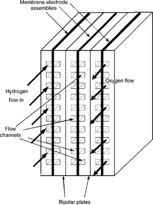
• an ion exchange membrane; the electrolyte should be an electronic insulator, and only allow ion transfer and not electron transfer;
• electrocatalyst layers (the electrodes) between a backing layer and the membrane where the cell reactions occur;
• an electrically conductive porous backing layer which conducts electrons and allows gases to permeate to the catalyst layers;
• bipolar plates (BP), or flow field plates, that deliver the fuel and oxidant to the MEA, electrocatalyst reaction sites, via flow channels and electrically connect cells in the stack;
• sealing gaskets, to achieve gas tight sealing for cell stacking and manifolds.
The combination of the membrane, electrocatalyst layers and porous backing layers is typically pressed together (under heat and pressure) to form the MEA. The catalytic electrodes are cast as thin-films which may be deposited onto the backing layer, then bonded to the membrane or applied directly to the membrane.
Generally PEMFC stacks are connected in a bipolar manner using the bipolar plates, such that current flows from one end of the stack to the other generating a high voltage for practical applications, determined by the number of cells in the stack. The role of the bipolar plate is to conduct the current from the anode of one cell to the cathode of the adjacent cell to the bipolar plate and to distribute the flow of reactant gases over the surfaces of the MEAs. Thus bipolar plates must be thin and electronically conducting to minimize ohmic voltage loss (and heat generation) as well as be chemical stable against corrosion and be impermeable to gases. Most large stacks will have plates with cooling channels to remove heat and control the temperature of operation of the MEAs. Designs and materials for bipolar plates vary and impact on the design and operation of the MEA.
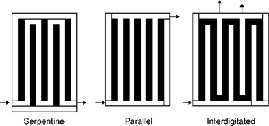
There is a range of bipolar plates flow field designs, to achieve good gas flow distribution, water removal and current distribution. Early flow fields were of the straight channel type, whereas a common design used is the serpentine flow field which produces a meandering path for the flow of gas. Interdigitated flow field design is used as a means to reduce the problem of cathode flooding by water. In this design, shown in Fig. 10.2, there are dead-ended inlet and exit channels. Thus the gas is forced to flow under the ribs of the flow field through the gas diffuser to exit the cell. This has the effect of causing a forced convective flow of gas in the electrode structure and removes some of the diffusion mass transport constraints in open-channel designs. The beneficial effect is also seen in the convective flow of water away from the catalyst layers. Improved performance PEMFCs have been reported using this approach (Nguyen and He, 2003).
10.3 Porous backing layer materials
Gas diffusion layer (GDLs) are essential components of PEMFCs and optimization of their functional properties requires understanding the role of key parameters: pore structure and porosity, surface morphology, hydrophobicity, gas permeability, transport properties on water management and gas supply. The functions of the porous backing layer or GDL are to (Cindrella et al., 2009)
(2) provide mechanical support to the membrane and catalyst layers,
(3) provide an electrical pathway for electrons,
The balance in the properties of a GDL to facilitate opposing flows of gas and water is important in its design. The porous backing layer is in immediate contact with the BP and the design of the BP has implications on the functional operation of the former. Where channels are adjacent to the backing layer, gases (and water) have immediate access and can readily diffuse to the electrodes, almost unhindered. In regions between channels, under the flow plate land (ribs), gases must be able to diffuse in-plane along the width of the gas diffuser as well as in-plane. Thus the aspect ratio of the land width and channel width in relation to the thickness of the gas diffuser is an important design consideration. The extent of compression on the gas diffuser is also important – that is, to avoid too high a reduction in diffuser gas porosity.
The cathode gas diffuser in a PEMFC has to accommodate transport of water vapour from the cathode to avoid electrode flooding, which could introduce oxygen mass transport limitations in the cathode. Also, if humidification is applied to maintain hydration of the membrane (to maintain high conductivity), the anode side gas diffuser must accommodate good water transport from the anode side flow channel towards the membrane.
A second requirement of the backing layer is to provide sufficient electrical conductivity for current flow between an electrode and a bipolar plate. The more porous the gas diffuser, the lower its conductivity and thus the greater will be its voltage loss. Thus there is some compromise between good gas and water vapour flow (high porosity) and good conductivity. Again the aspect ratio of the land width and channel width in relation to the thickness of the gas diffuser is an important design consideration. In the channel regions the diffuser must provide sufficient in-plane electrical conductivity to enable effective current flow from the land regions and provide reasonably uniform current distribution.
The backing layer is typically carbon-based in the form of a cloth, a non-woven pressed carbon fibre configuration or paper, or simply a felt-like material. The layer incorporates a hydrophobic material, such as polytetra-fluoroethylene (PTFE), to try to prevent liquid water forming pools within the pores of the backing layer which could impede the floe of gases towards the catalyst sites.
There are two basic approaches to constructing the MEA; one in which the catalyst layers are applied directly to the membrane and the other in which the catalyst layers are applied to the gas diffuser (Kocha, 2003). To achieve a compact design, carbon papers are used and in MEAs where catalyst layers are applied to the gas diffuser, the paper is coated with an additional PTFE-bonded carbon layer. This microporous layer (MPL) has much smaller pores than the carbon fibre diffuser and the carbon is often similar to that used in the electrocatalyst layer. The MPL’s main function is to occupy the larger spaces in the carbon paper surface and thus provide a less porous surface for application/deposition of the electrode layer. This prevents the electrocatalyst from being pushed inside the paper; whereby it would be less effectively used in the electrode reaction. The MPL also aids product water removal from the cathode as it creates a non-wetting surface within the passages of the backing material.
There is a limit to how much PTFE can be used in the MPL (and also the diffuser) as too much ‘wet-proofing’ can decrease electrical conductivity, due to its insulating properties which can increase contact resistance; which is also affected by the compression pressure used in stack assembly.
Other requirements of the diffuser are to provide mechanical support to the MEA and to provide good uniform electrical contact and thermal conductivity. In the latter case, heat generated in the cell reaction (mainly at the cathode) can be transferred to cooling channels through contact with the bipolar plate. The MEA must withstand any differential pressures between anode and cathode channels imposed during operation such that it is not compressed into the gas channels, which could result in blocking of flow and higher pressure drops.
10.3.1 Water management
Water management presents a dichotomy in the operation of a PEMFC system. Maintaining a high water content in the electrolyte is fundamental for high ionic conductivity in the PEM and in the ionomer phase of the catalyst layer. Otherwise the ohmic resistance of the whole cell will be relatively high. On the other hand, accumulation of liquid water should be avoided or else excess water will block the flow channels or/and the pores of the GDL and catalyst layer (CL) and then reduce the effectiveness of catalyst active sites. Liquid water present in the flow field channels and/or electrodes gas pores must be transported away from the catalyst layer by evaporation, water vapour diffusion and capillary transport of liquid water through the GDL into the flow channels of the flow field, and ultimately exhausted from the system. The extent of flooding and the effects of flooding strongly depend upon the interaction of the operating conditions, particularly under low gas flow rates and temperatures.
In the water transport mechanism inside a PEMFC, the product water is transported along the gas channels as well as in the direction perpendicular to the MEA. Protons are surrounded by a certain number of water molecules and when current is drawn from the fuel cell, they migrate from the anode to the cathode, through the membrane, carrying with them the associated water molecules, that is, the electro-osmotic drag. This, together with electrochemical water production, could result in accumulation of water at the cathode side. Conversely, this high water content creates a water concentration gradient between the anode and cathode which facilitates ‘back’ diffusion of water, which works against drying of the membrane from the anode side. The water gradient between anode and cathode is determined by the membrane thickness and water content and humidity of the reactant gases. These depend on the gas inlet humidification, the temperature and pressure in the gas channels and the current drawn from the cell.
At low current densities, back diffusion can dominate over electro-osmotic drag. At high current densities, electro-osmotic drag can dominate over back diffusion and thus the anode may tend to dry out, even if the cathode is well hydrated. Also, severe drying conditions can lead to irreversible membrane degradation (such as delamination and pinholes). Under conditions where freezing may occur, water accumulation may cause mechanical problems which affect the integrity of the MEA.
Accumulation of excess water and can happen at both the anode and the cathode side of the membrane and adverse consequences of flooding are many (Ji and Wei, 2009):
• Flooding leads to instant increase in mass transport losses, leading to gas starvation and an immediate drop in cell potential (current).
• Periodic build-up and removal of liquid water in the cell causes fluctuations in the cell performance, causing unstable, unreliable and inconsistent cell performance (Li et al., 2008b).
• Oxygen ingress into the catalyst surface will be hindered. Any lack of oxygen reaching the catalyst leads to oxygen under-stoichiometry or ‘starvation’ at the cathode. At steady-state conditions, the net mass flow rate of oxygen into the system is equal to the oxygen consumed by the oxygen reduction reaction (ORR). In transient conditions, a sudden increase in power requirement from the cell could mean that oxidant supply lags behind demand causing local oxygen starvation for the ORR, thus increasing oxygen concentration overpotential at the cathode.
• If oxygen were depleted at the cathode, proton (H+) reduction (PR), instead of ORR, could occur at the cathode and the cathode potential could fall from 1.23 to 0.00 V at current off and probably from 0.8 to −0.1 V at current on. This behaviour is known as the voltage reversal effect (VRE) in a PEMFC. In a stack of PEMFCs, when VRE happens in a single cell it can counteract – that is, reduce – the effective output voltage from other cells.
• low hydrogen flow rates can make more liquid water stay in the anode potentially leading to fuel starvation and thus a decline in fuel cell performance. Liquid water injection for cooling and humidification together with moderate cell temperatures (lower evaporation) can lead to water accumulation in the anode and hence flooding (Ge and Wang, 2007). Anode flooding in a single cell, within a fuel cell stack, could lead to fuel starvation and carbon substrate oxidation and also oxygen evolution. However, flooding at the anode happens less often than at the cathode.
Generally, flooding of an electrode is linked to high current density operation that can result in a water production rate greater than the removal rate.
10.3.2 Water management strategies
Vapour condensation and liquid water breakthrough in porous layers of PEMFC have been confirmed by environmental scanning electron microscope (ESEM) (Nam et al., 2009). The studies showed the presence (Fig. 10.3) of large droplets and high liquid saturation at the catalyst layer (CL) and GDL interface, due to the change in pore size. The liquid phase formation can reduce the efficiency of electrochemical reactions in CLs and increase the water saturation in GDLs. The subject of water formation and the mechanisms for formation of droplets in fuel cells has been reviewed by Bazylak (2009).
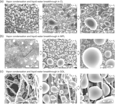
10.3 ESEM micrographs showing vapour condensation and liquid water breakthrough from (a) CL, (b) MPL and (c) GDL. For each, micrographs at three different elapsed times are shown Nam et al. (2009).
External gas humidification is a popular method for managing the water in a PEMFC. Alternatively an additional amount of liquid water can be injected directly into the fuel cell. Nguyen and He (2003) found that direct liquid water injection in conjunction with interdigitated flow fields was an extremely effective method of water management. This method is compact, easily controllable and needs little energy for humidification, although there is a risk of flooding in the fuel cell.
Flow field design can play a major role in water management. For serpentine flow channels, the reactant gas experiences a pressure drop and concentration change along the channel length. Thus the pressure reduction at corresponding locations between adjacent channels may become substantial, causing a pressure gradient across the porous electrode, larger than that along the channel direction. This can cause considerable cross leakage flow between adjacent channels, through the porous electrode, induce convection in the electrode, bringing in reactant gas and removing product water. Therefore, this flow field design with convective transport is the most widely used and has been adopted as an industrial standard although it has a number of problems, including substantial pressure drop and significant decrease of reactant concentration from the flow channel inlet to the outlet, leading to considerable Nernst losses for practical cells of large sizes. Most important of all, it often causes membrane dehydration near the channel inlet and liquid water flooding near the channel exit. There are of course several variants in the design of the serpentine flow fields provided by different manufacturers to fit various fuel cell power applications.
In the interdigitated flow field, where the flow channel design is dead-ended, the gas is forced to flow through the GDL and the reactants transport is now by forced convection which helps flush liquid water out of the electrode. However, high pressure losses can occur by forcing gas to flow through the GDL which may lead to a significant power requirement and also to membrane drying at low current densities.
Thinner membranes (circa 10 μm) have been shown to provide better water management due to the short distance for water back-diffusion process, which reduces the need for anode humidification. Although ohmic losses through the membrane are lower with thinner membranes, they are often associated with poorer durability and higher gas crossover rates, which has limited the practical membrane thickness to about 25–40 μm for PEMFCs.
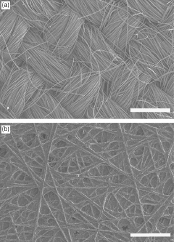
The choice of materials for GDL will depend on a trade-off between the properties of electronic resistivity, fraction of hydrophobic pores, gas permeability, pore size distribution and the surface morphology. A major technical challenge in a PEMFC is that it produces excess liquid water from the ORR. The performance of a GDL depends upon the macro-porous substrate and its gas permeability, which is related to larger pores, and water management, which relies on the fraction of hydrophobic pores. Hence development of highly functional GDLs with flexible characteristics of water draining, along with structural features to supply reactant gases to the catalyst layer is essential for eventual mass use of fuel cells for various power applications. Carbon fibre-based products are almost universally used for gas diffusers. These typically come in the form of non-woven papers or woven fabrics (cloths) as shown in Fig. 10.4. The popular choice of fibre is made from polyacrylonitrile (PAN) using a solvent spinning process.
An important feature of the gas diffuser is to provide good water management in the MEA and consequently diffusion materials are rendered hydrophobic by treatment with PTFE. PTFE loadings can be between 5% and 30% (by weight) and can be applied uniformly by dipping the diffuser material in an aqueous PTFE suspension followed by slow drying. If coating of only one side of a diffuser is required spraying or brushing of the PTFE suspension can be used.
The application of MPLs is widely adopted for PEMFCs. These layers, around 50 μm in thickness, are carbon/graphite powders bound with PTFE and typically provide pore sizes in the range of 100–500 nm, compared with 10–30 μm pores in the gas diffuser. As well as providing a suitable flat ‘surface’ for application of the catalyst layers they also encourage ‘wicking’ of water from the latter into the carbon diffuser and also help reduce contact resistance with the catalyst layer, which would otherwise occur. MPLs are formed onto the gas diffuser by using spraying, screen printing or doctor blade coating of a suitable paste/ink of carbon, binder and solvent (subsequently removed by evaporation) followed by heat treatment to sinter the binder.
The role of the GDL on the anode is slightly different to its role on the cathode. Whereas water formed on the cathode must be easily repelled from the catalyst surface to prevent flooding, the anode must retain some water to keep the membrane (and ionomer present in the catalyst layer) hydrated. This is especially true if the anode gas is dry.
Selection of suitable gas diffusion materials is carried out empirically using in situ fuel cell testing, which is guided by measurement of certain physical properties largely influenced by porosity and pore size distribution. Important characteristics of the diffusion layers are conductivity (or resistivity) mechanical strength and gas diffusivity. Carbon papers typically have 90% of the pore volume of sizes greater than 10 μm, with an average pore size of 30 μm. This generally means that they do not offer too much resistance to gas diffusion in the through-plane direction. In-plane gas permeation is of significance when interdigitated or serpentine flow fields are used. In serpentine flow, the potential effect of gas permeation/flow under ribs between channels with gas flowing in opposite directions is important. In interdigitated designs complete gas flow under the ribs through the gas diffuser between adjacent channels is required. Such fluid permeability is characterized by determination of the Darcy coefficient kD as defined by Darcy’s equation.
Through-plane resistance is usually expressed as an area resistance (ohm cm2) and is typically 5–30 mΩ cm2. Values increase with thickness and decrease with compression pressure. At compression pressures above 1 MPa, values are typically less than 10 mΩ cm2 approaching values of 5 mΩ cm2, which equates to a voltage loss of only 5–10 mV at a current density of 1 A/cm2. In-plane resistance is important for reasons of current collection from and current distribution (or reaction uniformity) over the electrodes. In-plane resistivities are of the order of 5 mΩ cm, which are an order of magnitude or more, smaller than the equivalent through-plane resistivities. Consequently, voltage losses in-plane between flow field ribs (~1–1.5 mm spacing) are of the order of a few millivolts.
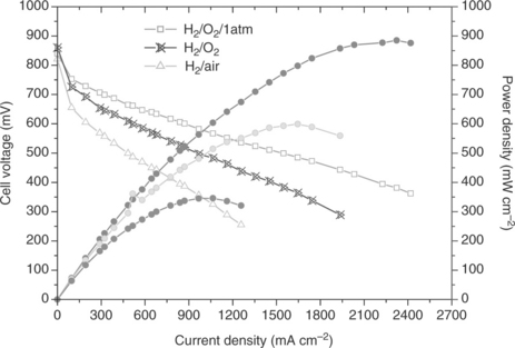
The cost of GDLs plays a role in reducing the fuel cell system cost for commercialization. The cost of the GDLs constitutes approximately 20% of the MEA and 5% of the overall fuel cell stack costs. Currently, there are several commercial GDL manufactures which include SGL Technologies GmbH, Mitsubishi Rayon Co. Ltd. (Japan), Ballard Material Products Inc. (Lowell, MA, USA) and Freudenburg (Germany). GDLs have been based on carbon or graphite fibre which are relatively costly and offer limited design flexibility. They also can result in fibre penetration through the polymer electrolyte membrane. To solve these problems, significant efforts are being made by find better materials, to enhance the mass penetration of fuel cell technologies into the market offering lower price, whilst maintaining performance targets. With proper design of the GDL the reduction in the fuel cell performance (peak power density) using air as an oxidant compared to that with oxygen can be minimized (Cindrella et al., 2009). High peak power densities using air are achieved, even though the partial pressure of oxygen is much lower (factor 0.21) in air. A good performance with H2 and air is due to the optimum properties of hydrophilic/hydrophobic balance, conducting network, pore dimension, distribution, etc.
10.4 Membrane materials
Membrane materials used for fuel cells can be classified as:
• partially fluorinated polymers;
• non-fluorinated membranes with aromatic backbone;
Perfluorosulphonic acid (PFSA) polymer is the most commonly used material for membranes for fuel cells. Due the high electronegativity of the fluorine atom they have a strong C–F bond and low polarizability. The main characteristics of PFSA membranes that are relevant to fuel cell operation are:
• high chemical stability: stable against strong bases, strong oxidizing and reducing acids, H2, and O2 at temperatures up to 125°C;
• mechanically strong and can be formed into thin non-porous films of thickness as low as 25 μm;
• high acidity with high conductivity (and ion exchange capacity) when wet;
• highly stable in operation; in selected tests lifetimes of over 50 000 h have been demonstrated.
Their thermal stability, chemical inertness and enhanced acidity of the sulphonic acid group saw the membranes originally developed for the chlor-alkali industry but to achieve high power densities in fuel cells much thinner membranes were developed. The PFSA consists of two ‘regions’, (1) a PTFE backbone, (2) side chains of vinyl ethers (e.g., –O–CF2–CF–O–CF2–CF2–) which terminate in sulphonic acid groups in a cluster region (Fig. 10.5). The principal reason why the ionomer membranes function well as ion conducting materials is that the sulphonate groups form into clusters, which are very hydrophilic and attract water. When these membranes become hydrated, the protons become highly mobile in the hydrophilic regions formed by the sulphonic acid clustering. These clusters effectively form channels through which H+ ion can move quite freely under a potential gradient. A consequence of this structure is that the membrane performance is critically dependent upon water content, as well as the transport of water through the clusters.
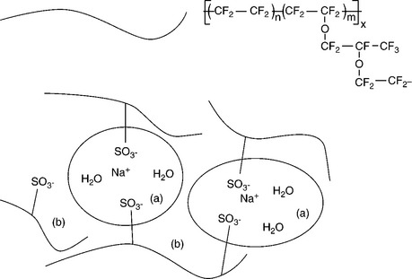
10.5 Structure of per fluorosulphonic acid co-polymer (Nafion®). The Yeager three-phase model, based on a three-phase clustered system with interconnecting channels within the polymer. (a) Cluster region of water-filled sulphonic acid groups, (b) interfacial region containing some pendant side chains, some water and sulphate groups.
The PFSA family of membranes include a range of alternative products from different manufacturers, using for example different side chains, but generally the inherent characteristics are similar. Companies who supply PFSA membranes, under the trade names of Nafion®, Flemion and Aciplex, are DuPont, Asahi Glass and Asahi Chemicals, respectively. Such materials are referred to as ionomers. Differences in materials are essentially in the length of the side chain and available thickness. For example, Nafion 117 has a thickness of 175 μm (the 7 in 117 refers to its thickness – seven thousandths of an inch). A standard for fuel cells is Nafion 112, which is 50 μm, whereas Nafion 111 is 25 μm. These thinner membranes have less mechanical strength and increased reactant crossover, which decreases fuel utilization and causes some electrode polarization as well as potential problems for electrode and material corrosion through formation of peroxy species. Thicker membranes reduce reactant crossover but at the expense of higher resistance and hence lower power density and efficiency. Although Nafion® type products have been the standard for PEM fuel cells, commercial markets with different operating conditions, is stimulating research of new membranes. For example, automobile companies would prefer operating temperatures above 100°C to reduce heat transfer requirements (i.e., the size of the radiator). However, PFSA membranes cannot maintain adequate membrane water content, and hence acceptable proton conductivity, at temperatures > 90°C, without operating at higher pressures, which introduces higher equipment (compressor) costs and energy loss from the fuel cell itself. In addition, the glass transition temperature of Nafion is 111°C, and thus PFSAs have limited operating temperature range as the mechanical stability is compromised at such temperatures.
One of the drawbacks of Nafion® and similar materials is the relatively high cost and engineering issues related to manufacture. Hence new alternative membranes and alternative manufacturing techniques are being developed. The method used to form membranes was typically melt-extrusion, which is being replaced by a solution-cast film process to reduce costs and improve manufacturing throughput efficiency. In solution casting, the ionic form of the polymer is solubilized in alcoholic solution (e.g., propanol) and then cast as a film of desired thickness. The conversion of the non-ionic polymer to an ionic phase is carried out prior to the solubilization of the polymer. The availability of this solubilized form of ionomer has also been found to be critical to the development of highly active electrode structures for MEAs.
The membrane is characterized by its equivalent weight (EW) and the ion exchange capacity. A typical EW range is 800–1100 milliequivalents per dry gram of polymer. Variations in EW affect the characteristics of the membrane. Lower EW results typically in higher conductivity and increased swelling of the membrane when exposed to water or humidity. The swelling of commercial Nafion® products is of the order of 25 wt%. Thus a material such as Nafion 112, with an EW of 1100, will increase in thickness from 50 to around 60 μm. Membrane swelling has implication in MEA fabrication and in operation. The proton conductivity of Nafion 112 is 0.06 S/cm at 100% RH and 30°C and 0.092 in liquid water at 20°C. Thus Nafion 112 has a cell resistance of around 0.1 Ω cm2 equating to a voltage loss of 100 mV at 1 A/cm2. However, as temperature increases these voltages losses can increase if sufficient hydration of the membrane is not maintained. The conductivity can fall by an order of magnitude at 80°C compared to that achieved at 60°C and lower.
There is a useful body of literature on transport properties of Nafion® type materials, including the effect of temperature and water content on proton conductivity, water and methanol transport, electro-osmotic drag and solubility and diffusion of gases (Doyle and Rajendran, 2003). In the case of oxygen this is particularly important for fuel cells where electrode construction in the MEA relies on the presence of ionomer for conductivity and also its relatively high oxygen solubility compared to water. Typically oxygen solubilities in Nafion® are 9.3-3.8 mol/m3 and oxygen diffusion coefficients are 9.95–8.7 × 10⁻⁷ cm2/s in the temperature range of 2–80°C.
An advance in membrane technology was achieved by using an internal support layer to enhance the mechanical strength of the membrane film, when using very thin membrane to reduce cell voltage losses. An example is the Primea 55 and 56 series membranes manufactured by W. L. Gore (Cleghorn et al., 2003) who developed composite membranes to reinforce Nafion®. Such membranes provided good mechanical stability by using an expanded, microporous, high-porosity PTFE membrane, into which the ionomer is introduced. This enabled the use of ionomers of EW < 1000, which had high conductivity but poor stability as stand-alone membranes. Membranes are typically 25 μm thick with conductivities up to twice that of Nafion 112 under equivalent conditions of humidity and temperature.
Asahi Glass developed a Flemion type membrane using a PTFE fibril support to provide mechanical stability. Such membranes have resistivities only slightly larger than the un-reinforced membranes (7–8 Ω cm) but have around five times the tear strength and four times the elastic modulus at 80°C and 95% relative humidity (RH) (Hommura et al., 2003).
In general, lower cost membranes that exhibit low resistivity are needed to promote lower cost PEMFCs. Thinner membranes with lower resistivity could contribute to power density improvement, which is particularly important for transportation applications; characterized by high current density operation. Although membrane development is a particularly active field a major hurdle is establishing long-term durability. Ballard produced their BAM3G membrane based on polymerization of α,β,β-trifluorostyrene which included monomers from a group of substituted α,β,β-trifluorostyrene. The membrane has high heat stability, chemical resistance and favourable mechanical properties (e.g., tensile strength) compared with the single polymeric material based on α,β,β-trifluorostyrene alone (Cleghorn et al., 2003).
The area of PEM has been the subject of much research and reviews, most recently by Peighambardoust et al. (2010). The structure, physical properties and performance of membranes in fuel cells is summarized in Table 10.1 (Smitha et al., 2005). From the table it can be noticed that the perfluorinated ionomers possess most of the desired properties for fuel cell applications.
Table 10.1
The structure, physical properties and performance as membranes in fuel cells
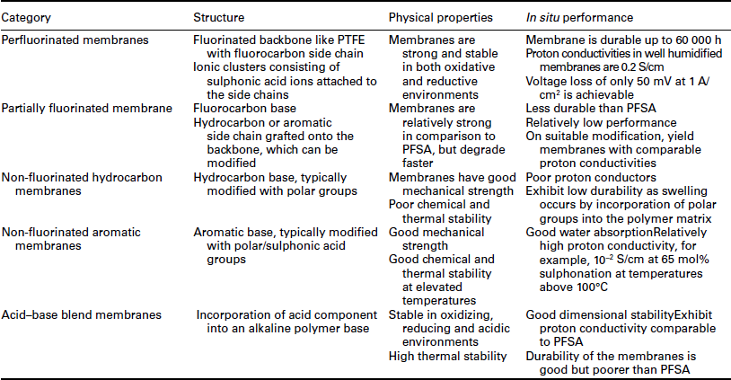
Source: After Smitha et al. (2005).
Non-fluorinated membranes are made from aliphatic or aromatic polymers with benzene ring structures in the backbone or in the pendant groups attached to the membrane polymeric backbone. Hydrocarbon membranes are less expensive than PFSA membranes and their structure permits the introduction of polar sites as pendant groups in order to increase the water uptake. However, they may not offer similar stability to PFSA membranes. Mehta and Cooper (2003) produced a short list of 16 possible membrane materials for fuel cell applications. The use of partially sulphonated polyarylenes has been the subject of significant research due to their low cost and good stability. The aromatic rings offer the possibility of electrophilic as well as nucleophilic substitution. Materials such as polyarylene sulphone (PSU), poly arylene ether sulphone (PES) and poly arylene ether ether ketone (PEEK) can be directly sulphonated using concentrated sulphuric acid or chlorosulphonic acid (Smitha et al., 2005).
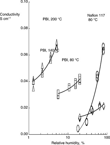
Acid–base complexes considered for fuel cell membranes involve incorporation of an acid component into an alkaline polymer base to promote proton conduction. Such complexes can maintain high conductivity at elevated temperatures without suffering from dehydration effects. The poly(2,21-(m-phenylene)-5,51-bibenzimidazole)/phosphoric acid (PBI/H3PO4) complex has shown a great deal of potential for medium-temperature fuel cell applications. Such complexes are sensitive to the acid loading and temperature. PBI is a generic name for a number of similar polymers which includes AB–PBI which is similar to the compound above, but without the connecting phenyl group. The ionic conductivity of PBI varies with the degree of acid loading and increases with temperature up to 175°C, following an Arrhenius law. Conductivity also increases with increase in RH (Fig. 10.6); which is attributed to the distribution of phosphoric acid species formed as phosphoric acid loses water to form poly-phosphoric acids. At 450% acid loading, the conductivity of PBI membrane was about 4.6 × 10⁻² S/cm at a temperature of 165°C. At very high acid content (around 1600%), the conductivity reached high values up to 0.13 S/cm.
Other approaches to high-temperature membranes are based on the modification of Nafion® with inorganic materials such as SiO. and TiO2 to improve their mechanical strength, thermal stability and water retention at elevated temperatures, with reports of conductivities close to that of Nafion®, while operating at up to 120°C at low hydration levels (Zhang et al., 2006).
In attempts to use Nafion® materials at higher temperatures (> 100°C), composites with zirconium phosphate and Nafion 115 have been made (Jones and Roziere, 2008). The area resistance of such membranes was low at 0.12 and 0.08 Ω cm2 at 90 and 140°C, respectively, when measured in a 4.0 M methanol solution at 4 bar pressure. The zirconium phosphate was suggested to be responsible for water retention at high temperatures. The literature is quite large on the search for suitable PEM made from polymers and inorganic compounds. As well as PFSA materials, sulphonated PEEK and polysulphone have been used as composites with solid acids and heteropolyacids such as tungstophosphoric acid.
Phosphoric acid-doped polybenzimidazole (PBI) has also been incorporated with inorganic proton conductors such as zirconium phosphate (ZrP, Zr(HPO4)2 · nH2O), phosphotungstic acid (PWA, H3PW12O40 · nH2O PWA) and silicotungstic acid (SiWA, H4SiW12O40 · nH2O) (Jones and Roziere, 2008) and boron phosphate (Zaidi, 2005). Proton conductivities are found to be dependent on the acid doping level, RH and temperature. The conductivity PBI membranes with a H3PO4 loadings 5.6 (H3PO4 per repeat unit of PBI) at 200°C and 5% RH is 6.8 × 10⁻² S/cm. A higher conductivity of 9.6 × 10⁻² S/cm is obtained for composites containing 15 wt.% of ZrP under the same conditions (Zaidi, 2005).
The heteropolyacids (HPAs) powders are well-known inorganic solid acids with high acidity and proton conductivity. However, their chemical stability is unsatisfactory due to their hygroscopicity. Caesium salts of heteropolyacid (CsHPA) are insoluble in water as reported by Li et al. (2008a). In this work, PBI/Cs2.5H0.5PMo12O40/H3PO4 composite membrane achieved high conductivity (> 0.15 S cm−1) and in a fuel cell gave a high power density of 0.7 W cm−2 at atmospheric pressure and 150°C. These data indicate that Cs salts of heteropolyacid could be a good candidate to form composite membranes with PBI for intermediate-temperature fuel cell applications.
10.4.1 Alkaline anion exchange membranes
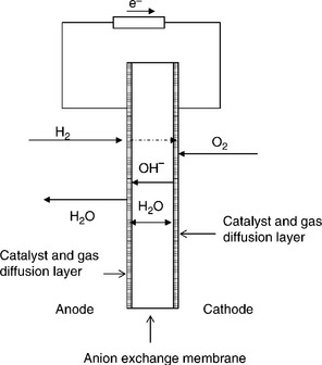
Solid (cation-free) OH− ion conducting polymer alkaline electrolyte membranes (AEM) offer a solution to many of the limitations of PEMFC. AEMs are solid polymer electrolyte membranes that typically contain positive ionic groups (e.g., quaternary ammonium (QA) functional groups such as poly-N+Me3) and mobile negatively charged anions (e.g., usually OH–). AEMs exhibit several advantages over PEMFCs including the enabling of faster catalysis of fuel cell reactions (e.g., ORR) under alkaline conditions compared with acidic conditions, therefore providing lower activation losses. Also, non-noble metal catalysts can be effectively used and a number of cheap materials for cell components due to less corrosive environment. Water management, crossover and electrode flooding issues in AEMs are different to those in PEMFCs as ion transport is away from the cathode towards the anode (Fig. 10.7).
Research on anion exchange membranes with good ionic conductivity and chemical stability in alkaline media has been carried out by several groups (Slade and Varcoe, 2005). However, in comparison to PEMs this activity is in need of greater effort to provide suitable membranes which have good conductivity and stability in hydroxide ion environments. Membranes based on radiation-grafted polyethylene polymer films have produced high hydroxide ion conductivities and good fuel cell performance (Mamlouk et al., 2011a).
Robertson et al. (2010) have produced new cross-linked membranes using cyclooctene that have conductivities of 0.111 S cm−1 m at 50°C. The materials exhibit good mechanical stability and should be durable as the tetraalkylammonium ion does not contain β-hydrogen. Such high conductivities which are comparable to values for Nafion 112 hold great promise for the development of fuel cells.
What still has to be demonstrated is the formation of MEAs with suitable conductivity, activity and stability that achieves performance comparable to that of PEMFCs. A key to this is the development of soluble forms of the membrane to act as ionomers in the catalyst layers. A number of interesting ionomer materials are starting to emerge such as solvent processable tetraalkylammonium-functionalized polyethylene with good conductivities of 40 mS/cm at 20°C and 59 mS/cm at 50°C (Kostalik et al., 2010).
10.4.2 Direct methanol fuel cell (DMFC) membranes
Methanol has long been considered as a fuel for fuel cells because as a liquid it is easily stored and transported in comparison to hydrogen. In a direct methanol fuel cell (DMFC), methanol dissolved in water is supplied to its anode, and the methanol is oxidized to carbon dioxide and protons:
The protons pass through the membrane and combine with oxygen to produce water. As such, membranes are required with similar characteristics to those used for hydrogen fuel cells. Notably, however, methanol cells use aqueous solutions which generally provide sufficient water to keep the membrane hydrated even at temperatures around 100°C. However, a major factor is that most PFSA membranes are permeable to methanol (methanol crossover) which can affect the performance of the cathode. This crossover results in ‘poisoning’ of the cathode catalyst by methanol, coupled with oxidation of methanol, resulting in an inefficient cathode reaction. These factors give rise to low overall performance, particularly at low temperatures. Methanol crossover also wastes fuel and reduces cell efficiency. Another issue with the DMFC is that Ru, which is a component of the anode binary (Pt–Ru) catalyst, also undergoes crossover (migration, diffusion). Such crossover leads to deposition on the cathode and has a negative impact on performance for DMFCs (Scott and Shukla, 2006).
Generally, membranes that have been evaluated for hydrogen PEMFCs have been tested for the DMFC. Because of the methanol crossover problem thin membranes are not suitable for the DMFC, as they tend to allow large crossover rates of methanol. For example, thicker Nafion 115 and 117 rather than Nafion 112 (used in the PEMFC) have much lower methanol crossover rates, but of course have a lower ionic conductance. Even with these relatively thick membranes, methanol feeds are relatively dilute aqueous solutions, typically 1–2 M in concentration, compared with an anode stoichiometric requirement of 17 M. A number of inorganic–organic composite membranes and co-polymer membranes have been investigated for the DMFC (Scott and Shukla, 2006) with varying success.
Low-cost grafted membranes have been prepared by processes based on electron beam or gamma irradiation, subsequent grafting, cross-linking and sulphonation of a range of polymer films. The polymer films include polyethylene, polyvinylidene flouride (PVDF) and ethylene-tetrafluoroethylene (ETFE). DMFC assemblies based on these membranes show cell resistance and performance values comparable to Nation-117.
Oxidation of methanol can be promoted substantially by operating the solid polymer electrolyte (SDPE)–DMFC at temperatures above 100°C. The kinetics of oxidation will be accelerated and the influence of poisoning species, such as adsorbed CO species, will be reduced. However, the ionic conductivity of Nafion® falls considerably above 100°C due to loss of water, which is necessary for its conductivity, by evaporation. Composite membranes that exhibit fastion proton transport at elevated temperatures are needed for proton exchange membrane fuel cells operating between 100 and 120°C. Several approaches have been pursued to resolve this issue, such as utilizing different proton-conducting ionomer polymers and using hybrid membranes (Scott and Shukla, 2006). Another approach is the use of proton-conducting membranes based on acid-impregnated ionomer polymers, such as polystyrene sulphonic acid membranes imbibed with sulphuric acid, Nafion® impregnated with 85% phosphoric acid, or non-volatile hetro-polyacid impregnated Nafion® membranes. A related strategy is to utilize acid-doped non-isomeric polymers, such as phosphoric acid-doped poly-benzimidazole (PBI) or tri-fluoromethane sulphonic-acid-doped polyvinylidine-fluoride-hexa-fluoropropylene (PVDF-HFP).
10.5 MEA electrode catalyst layer
The catalyst layer in a MEA is formed by connecting nano-particles of catalyst with a binder, typically based on PTFE. The bound catalyst structure is applied either to the membrane (catalyst-coated membrane, CCM) or first to the backing layer of the GDL and then attached to the membrane (catalyst-coated diffusion layer, CCDL). The binder creates the structure of the electrode, enabling access of gas (hydrophilic regions) and movement of water (in hydrophilic regions).
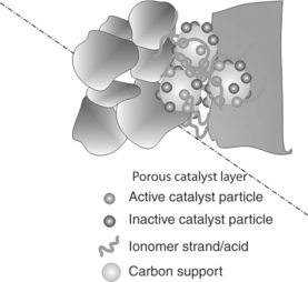
One of the most important features required of any electrode structure is intimate contact of catalyst particles and the membrane to ensure high proton mobility. Consequently, as PTFE binder is not ionically conducting, electrode structures were developed using hydrophilic ionomer (perfluoro-sulphonic acid) as a binder. In most MEAs, the catalyst is covered or partially covered in a layer of electrolyte ionomer (Fig. 10.8), which provides ‘bridges’ for good proton mobility and also provides good oxygen solubility. Thus, in principle, the electrode layer has all the requirements for the electrochemical reaction, that is, proton conductivity (when wet), electron conductivity throughout the structure, reasonable oxygen solubility near the catalyst, thus creating ‘maximum’ effective use of the catalyst surface.
A number of methods of applying catalyst layers to the MEA have been researched and developed, although not all of these use ionomer impregnation. CCDL methods include:
1. Spreading a paste of carbon supported catalyst and binder onto wet proofed GDLs using rollers or tape casting.
2. Spraying an ‘ink’ of catalyst suspended in an alcohol, water and colloidal PTFE (with or without ionomer) mixture onto the GDL. The electrode can be sintered in between successive sprayed coatings.
3. Catalyst powder deposition using a dry mixture of catalyst and PTFE powder (formed in a knife mill) followed by rolling the electrode after deposition to improve catalyst adhesion. The method can also be used to form CCMs.
Catalyst-coated membranes can also be formed by simply spraying or painting a catalyst/ionomer ink onto the membrane.
A ‘decal’ method was developed by Gottesfield et al. in which a mixture of Pt catalysts and ionomer (with glycerol as an option) in an ink was first deposited on a PTFE sheet. The catalyst-coated PTFE sheet is then hot-pressed onto the ionomer membrane and the PTFE sheet is then pealed off to form the CCM. This work was instigated by the discovery that Nafion® can be converted to a thermoplastic form by ion-exchanging it with large hydrophobic counter-ions such as tetrabutylammonium. In the thermoplastic form, the ionomer can be processed in a melted phase, which leads to the possibility of fabricating ionomer structures by molding and extruding (Wilson et al., 1995). Sputter deposition can also be used to form both CCMs and CCDL electrodes.
With both the CCM or CCDL methods the final stage is the production of the MEA by combining the membrane and two electrode layers and GDLs. This is typically achieved by hot pressing the three components together, that is either the two CCDL and the membrane or the CCM and two GDLs. Hot pressing will clearly dry out the membrane and catalyst layers, but these can usually be re-hydrated by immersion or contact with water or humidified gases. Pre-treatment of the MEA prior to hot pressing to remove trace organics and metal impurities can also be applied. This is typically achieved by successive immersion in peroxide and sulphuric acid solutions and rinsing in boiling demineralized water.
Overall the method used to produce the MEA will depend to a large extent on the nature of the membrane, the ionomer and selected binder and the electrocatalysts. For example, different carbon catalyst supports will likely require modification in the ‘ink’ composition in terms of degree of hydrophobicity and type of solvent.
In the development of new membranes, the availability of a solvent-based ionomer to use in building the electrode layer is an important issue. In addition, the thermal stability of the ionomer membrane becomes an important factor. For example, several AAEMs have been produced which have limited stability above 60–80°C and thus hot pressing on the MEAs is then not possible, although cold pressing under pressure is used (Mamlouk et al., 2011b).
10.5.1 Catalysts
The catalysts used in the PEMFC are based on platinum for both the anode and cathode. The anode catalyst used in most modern PEMFCs using hydrogen is a supported Pt catalyst, typically on carbon blacks or graphite. For other fuels, such as reformate (containing H2, CO2, CO and N2), the desired catalyst is an alloy of platinum containing ruthenium. Oxygen reduction electrodes use either the platinum metal or the supported Pt catalyst.
Platinum catalysts are expensive and thus there have been numerous efforts to minimize the use of platinum in the catalyst layer by increasing activity. This has invariably been achieved by using a small particle size, around 3–5 nm, on a carbon support. A high degree of optimization of the electrode structure has taken place to enable low loadings of Pt catalyst; of the order of 0.1–0.2 mg/cm2 for anodes and 0.2–0.5 mg/cm2 for cathodes, to be used. However, the cost of catalyst is still relatively high and in need of further reduction to make fuel cells more attractive for commercial applications. Thus, for example, a PEMFC with a power capability of say 1 W/cm2 would require up to 0.7 g Pt per kW. This translates into a cost of approximately £30 per kW. Of course there has been and continues to be research into alternative materials to platinum. Most attempts focus either on other precious metal or on platinum alloys (usually with transition metals). In addition, alternative carbon supports and alternative support materials are being researched; particularly for the ORR where most of the cell voltage polarization losses occur.
It is accepted that to achieve high power performance from MEAs, electrocatalysts must be formed as nano-particles usually <10 nm in diameter to provide sufficient surface area to support high overall current densities. This is because in most cases the catalyst is coated with an ionomer which limits, for example, the oxygen concentration at the catalyst surface. Although the ionomer is needed for good proton conductivity, the ionomer films must not be too thick as this will increase oxygen diffusion limitations at the electrode. Thus local current densities at the catalyst/ionomer interface are very small so that only small electrode polarization occurs, avoiding therefore excessive electrode voltage losses.
The preparation of catalyst nano-particles can be divided into chemical or physical methods. Physical methods include atomization of metals in a vacuum by thermal evaporation or sputtering. Chemical methods used for preparation of fuel cell catalysts involve the reduction of a metal precursor (in an ionic or molecular state) under controlled conditions that limit the growth of the metal atoms as they form nano-particles (Chan et al., 2004).
One of the most important factors for catalyst formation is the morphology and materials characteristics of the support. A range of different carbons such as activated carbons, carbon blacks, graphitic carbons, nano-rods and tubes, and various meso-porous structures have been used. The formation of meso-porous structures with tuneable pore size can offer better mass transport properties when used in the production of nano-catalysts. Such supports are produced by a templating method starting with highly ordered silica templates.
10.6 MEA performance
Fuel cell performance is affected by a range of factors directly or indirectly governed by the MEA structure and its electrode and membrane components. An ideal electrode is one that maximizes the active surface area of catalyst per unit mass of catalyst and per unit electrode area and minimizes barriers to reactant transport and ionic and electronic (resistances) conduction. It should also ensure stable performance with time – through stability of the structure and materials and through tolerance to any potential detrimental effects of trace impurities. Importantly, this all has to be done within cost limits of materials (e.g., Pt). Formation of nano-particle catalysts tends to make the materials less stable and susceptible to sintering and particle growth. Additionally, carbons are unstable in fuel cell oxidation operating conditions (>0.4 V) but such reactions are very slow in PEMFCs operating at low temperatures. Heat treatment at temperatures > 2200°C can be used to produce more graphitic structures which are less prone to oxidation.
The performance of PEMFC depends on the thickness of the electrode layers. On the one hand a high catalyst loading is desirable to give a high catalyst activity per unit cross-section area. However catalyst layers that are too thick would have greater resistance and be affected more by mass transport limitations and by non-uniformity in current distribution – in the absence of diffusion limitations in electrodes, current densities are higher locally nearer to the membrane. Catalysts further from the membrane are subjected to smaller and smaller current densities which reduces the overall effectiveness. As PEMFC technology is still dominated by Pt as the preferred catalyst this perhaps fortuitously, limits the electrode thickness.
The thickness of an electrode is determined by the catalyst support and the loading of catalyst on the support. Catalysts are now available with 60–80% Pt deposited onto the carbon which enables significantly thinner electrodes to be produced. For example, with 60 wt% Pt on carbon, a loading of 0.3 mg cm−2 cross-section area would provide an electrode thickness around 11 μm. However, fabrication of high-Pt loading catalysts can result in a reduction in the active catalyst area per unit mass and may make the catalyst more susceptible to sintering over time.
10.6.1 Polymer electrolyte membrane fuel cells (PEMFCs)
Over the years a number of studies have examined the influence of electrode parameters on PEMFC performance. Qi and Kaufman (2003) of the H Power Corporation reported data on low-Pt loading high-performance cathodes for PEM fuel cells.
The ionomer content in the catalyst layer has also been studied (Song et al., 2001). An optimal Nafion® content would mean that the electronic and ionic connections were well balanced: too small a Nafion® content would mean not enough catalyst particles connected ionically connection to membrane, whilst too high a Nafion® content would mean that more catalyst particles become electronically isolated from the diffusion layer. In addition, excess Nafion®, which is hydrophilic, can potentially trap water in the catalyst layer and block reactant gases access.
MEA performance is affected by the cell and stack design. An important feature of cell design is to try to ensure that water does not accumulate in the electrode region and block or ‘flood’ the electrode, which leads to restricted oxygen access and loss in power, especially at high current densities. However, a critical requirement is to maintain high water content in the electrolyte to ensure high ionic conductivity, which again is particularly crucial at high current densities. Water transport is a function of the operating conditions (temperature, pressure, gas flow), and also of the characteristics of the membrane and the electrodes.
PEMFC performance
Several companies manufacture MEA products, such as Ballard, 3M corporation, Johnson Matthey Fuel Cells, DuPont, Toyota and General Motors. For example, DuPont Fuel Cells offers DuPont™ Membrane Electrode Assemblies (MEAs) for H2, hydrogen reformate and direct methanol applications. The MEAs are available in three- and five-layer configurations: as a catalyst-coated membrane and GDL combined. There are three types currently available; based on GDL with Nafion® PFSA membrane border, with reinforced border and with an edge seal (GDL to edge, with an impregnated polymer seal). The integrated seals and gaskets enable a compact design, while performing its primary function of eliminating leaks and over-compression. The thickness and the compressibility of these gaskets dictate the eventual compression levels experienced by the GDLs. One factor to be aware of is the potential for contaminants arising from the seals which may poison the catalysts or degrade the MEA over time. So far, there has been little detailed information in the literature on the effects of various gaskets on MEA performance or potential degradation.
DuPont Fuel Cells (2010) has performed single-cell testing at various pressures, temperatures and humidification to approximate portable, stationary and automotive fuel cell operating conditions. Data are based on performance results for a five-layer MEA based on 1-mil Nafion® PFSA membrane, DuPont Fuel Cells’ hydrogen-series electrode and proprietary gas diffusion media. Performance under pressure (1.6 bar) with humidified hydrogen at 80°C, and with atmospheric gas at 60°C gave current densities of 1.6 A cm−2 at a voltage of 0.65 V.
Ballard (2010) make carbon fibre paper GDLs for PEMFC which give very high-performance characteristics. Their AvCarb® EP40 products offer higher permeability, lower bulk density, and improved pore structure while maintaining mechanical properties. Materials are ready to assemble with a CCM, or can themselves be catalyst coated. They provide excellent high current density performance over a wide range of cell operating conditions – wet or dry. This optimized MPL-coated, PTFE-treated material has demonstrated H2–Air polarization results at 65°C and 1.5 bar pressure of 1.75 A cm−2 at a voltage of 0.65 V, as well as continuing performance above 2.5A/cm2 with a PFSA type membrane.
3M Corporation membrane technology is based on PFSA but with a slightly shorter side chain than other materials, that is, without the pendant –CF3 group (Hamrock et al., 2009). This produces a higher degree of crystallinity and allows lower EW membranes which gives higher conductivity. The lowest EW of 650 gives a conductivity of 93 mS/cm at 120°C and 50%RH at 2.5 bar pressure, which is twice that obtained by Nafion®. Electrode performance of a standard 100 cm2 seven-layer MEA manufactured by the 3M operating on hydrogen and reformate at 70°C is typically, current densities of 600 mA/cm2, at 0.7 V using reformate fuel. This MEA is produced using high-speed, continuous, automated, high-volume manufacturing assembly equipment. The durability of the electrodes has been demonstrated with tests with reformate in excess of 10 000 h, significantly exceeding the USA Department of Energy 2015 target of 5000 h (equivalent to approximately 50 000 miles).
Intermediate-temperature PEMFC
The operation of PEMFC can potentially be improved at temperatures above 120°C (up to 200°C) by improved kinetics of the cathode and anode reactions and the reduction of the adsorption and electro-oxidation of poisoning species such as CO. Nafion®-type membranes dehydrate rapidly at such temperatures unless high pressures are used. Hence new ion exchange membranes have been developed for these operating temperatures that do not rely on water of hydration for conductivity. A candidate membrane material for these higher temperature PEMFC applications is PBI. PBI is a relatively low-cost polymer which has good mechanical flexibility at elevated temperature and excellent stability in reducing and oxidizing environments. PBI is a basic polymer (pKa ≈ 6.0) which readily absorbs acid which provides it with its ionic conductivity. The acid-impregnated PBI membranes are conductive above 100°C even when dry. One of the main attractions of PBI is that the solution form of the polymer can potentially be used to cast membranes and be used in the catalyst ink in the preparation of bonded catalytic electrodes for fuel cells.
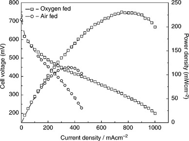
The conductivity of PBI can approach the target of 0.1 S/cm set for high-temperature membranes. With the acid-impregnated membranes there are potential problems with acid migration, corrosion of cell components, adsorption of anions on the catalyst and acid volatility. As a result, similar precautions as in a PAFC (avoiding liquid water, corrosion protection) are necessary. Typical high-temperature PEMFC performance with PBI membranes is shown in Fig. 10.9.
10.9 Performance of a PBI-based PEMFC loaded with H3PO4. Temperature: 175°C, loading Pt: 0.95 mg/cm2.
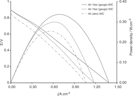
Other high-temperature polymers have also been considered for fuel cells and include the use of aromatic polyethers with pyridine units (as developed by Advent TPSR). Such membranes operate at up to 200°C and are imbibed with up to 200% phosphoric acid. Typical performance data using reformate gas and air, reported by Neophytides and Kallitsis (2010), are shown in Fig. 10.10.
10.10 Typical performance data using reformate gas and air. (Source: Neophytides and Kallitsis, 2010.)
10.6.2 Alkaline anion exchange membrane fuel cells
In comparison to PEMFCs, the performance of AAEMFCs has been limited to relatively low power densities. However, quite recently some of the best performance data to date has been reported by Tokuyama (Fukuta et al., 2010) using a newly developed AAEM. The performance with Pt/C catalysts (0.5 mg/cm2 loading), with a catalyst to ionomer ratio of 7:3 and carbon paper-based flow fields, at 50°C with 95% RH air (CO2 free), gave a peak power density above 300 mW/cm2. Performance stability, for more that 200 h, has been demonstrated at a cell voltage of around 0.6 V.
Recent work on AAEMFC using radiation grafted membranes made from high-density polyethylene and has shown very good fuel cell performance (Fig. 10.11). with a peak power density greater than 200 mW/cm2 at a temperature of 60°C (Mamlouk et al., 2011b). A feature of the fuel cell is that performance is detrimentally affected by the behaviour of the anode which is in part associated with the mass transport and water transport associated with electro-osmosis from the cathode to the anode.
10.6.3 Direct methanol fuel cells (DMFCs)
One of the key problems impeding the development of SPE-DMFCs is the properties of the available proton-conducting membrane. Owing to the low reactivity of methanol as well as the low conductivity of commercially available PEM, namely Nafion®, at ambient temperatures, it is necessary to have an operating temperature near 100°C for SPE-DMFCs for high power density performance. The problem of methanol crossover associated with the Nafion® membranes is detrimental to the performance of a SPE-DMFC since it reduces both the coulombic efficiency of the fuel cell and the cell voltage. Thus, generally, DMFC performance (Scott and Shukla, 2006) is significantly poorer than that of PEMFC (see Fig. 10.12). Overall, the challenge in DMFCs has been to try to provide a membrane with low crossover and reasonable conductivity and to design electrode structures, which reduce the impact of crossover.
The type of diffusion backing in the MEA and its degree of hydrophobicity can also affect the DMFC performance. Increasing competition from alternative proton-conducting membrane technologies led to improvements in DuPont’s Nafion® product Gen IV MEA with 20% increase in power density, twice the durability and significantly lower catalyst loading (DuPont, 2010). 3P-energy developed a PFSA membrane with some 20 times lower MCO than Nafion® membrane which was able to operate with a higher methanol concentration, resulting in a higher power density.
Operating at low temperature reduces the methanol crossover rate but anode and cathode catalyst activity are relatively low. Consequently, higher temperatures approaching 100°C are preferred as these benefit the ORR and anode activity, consume more methanol at the anode side of the cell and thus reduce the concentration of methanol that can transfer across the membrane to the cathode. However, Nafion® stability can be compromised above 100°C and blend or composite membranes have been investigated using fillers such as zirconium phosphate and silica. For example, a Nafion®/zirconium phosphate membrane is stable at 150°C had a membrane resistance of 0.08 Ω cm2 and gave a maximum power density of 260 mW cm−2 for a DMFC with air. The ZrP additive enhanced water retention characteristics, raised the maximum working temperature, and increased the dry weight and thickness of the membrane by some 30%. The membrane resistance decreased from 0.12 cm2 at 90°C to 0.08 cm2 at 140–150°C.
For several DMFC applications as portable power, for example, laptop computers, low temperature operation is required. Several companies have been developing MEA products for such markets. Polyfuel (2010) technology using a 45 μm thick polycarbonate membrane has one of the highest power densities of 80 mW/cm2 at 40°C, the best lifetime (5000 h) and low methanol crossover.
10.7 Conclusions
The MEA in the polymer membrane based fuel cells is the component which is largely responsible for governing fuel cell power output. PEMFC using hydrogen can generate high power densities, in excess of 1.0 W/cm2 of cross-sectional area, and high current densities (>>1 kA/cm2) at relatively high efficiency or single-cell voltage (> 0.65 V). Hence they are attractive for certain mobile and portable applications and especially as a prime motive power for automobiles and other forms of transport. The performance of the MEA is governed by the characteristics of its components such as the membrane, catalyst layers and gas diffusion layers. Understanding the behaviour of these components and how they interact is essential for high power performance attainment. Such understanding is also needed to ensure that the cost of the components is low so as to achieve acceptable costs for commercial applications. Recent developments in PEMFC have seen the emergence of higher temperature cells which operate without humidification at temperatures up to 200°C. Such PEMFCs can also be used with other fuels and notably using methanol. More recently a newer technology based on the use of hydroxide ion conducting membranes has started to be developed which potentially could match the performance of PEMFCs with a lower cost.
10.8 References
Ballard, 2010.. www.ballard.com/files/pdf/Spec_Sheets/MGL_1.4.pdf
Bazylak, V. Liquid water formation in PEM fuel cells. A review. Int. J. Hydrogen Energy. 2009; 34:3845–3857.
Chan, K.Y., Ding, J., Ren, J., Cheng, S., Tsang, K.Y. Supported mixed metal nanoparticles as electrocatalysts in low temperature fuel cells. J. Mater. Chem.. 2004; 14:505–516.
Cindrella, L., Kannana, A.M., Lina, J.F., Saminathana, K., Hoc, Y., Lind, C.W., Wertze, J. Gas diffusion layer for proton exchange membrane fuel cells. A review. J. Power Sources. 2009; 194:146–160.
Cleghorn, A., Kolde, J., Liu, W., Catalyst coated composite membranesVielstich, W., Lamm, A., Gesteiger, H.A., eds. Handbook of fuel cells, Vol. 3. England: J Wiley, 2003. [Chapter 44].
Doyle, M., Rajendran, G., Perfluorinated membranesVielstich, W., Lamm, A., Gesteiger, H.A., eds. Handbook of Fuel Cells; Vol. 3. J Wiley, England, 2003:351–395. [Chapter 30].
DuPont, 2010. http://www.dupont.com/fuelcells
Fukuta, K., Inoue, H., Chikashige, Y., Yanagi, H. Improved maximum power density of alkaline membrane fuel cells (AMFCs) by the optimization of MEA construction. 217th ECS Meeting. 28(30), 2010.
Ge, S.H., Wang, C.Y. Liquid water formation and transport in the PEFC anode. J. Electrochem. Soc.. 2007; 154:B998–B1005.
Hamrock, S., Abulu, J., Duru, C., Emery, M., Pierpont, D., Haugen, G., Haugen, R.S., Ren, L., Schaberg, J., Sharma, M.N., Yandrasits, M., New Fuel Cell Membrane Development at 3M. Fuel Cell Seminar. 2009. [November 18].
Hommura, S., Kunisa, Y., Terada, I., Yoshitake, M. Characterization of fibril reinforced membranes for fuel cells. J. Fluor. Chem.. 2003; 120(1):151–155.
Ji, M., Wei, Z., A review of water management in polymer electrolyte membrane fuel cells. Energies 2009; 2:1057–1106, doi: 10.3390/en20401057.
Jones, D., Roziere, J. Advances in the development of inorganic–organic membranes for fuel cell applications. Adv. Polym. Sci.. 2008; 215:219–264.
Kocha, S.S., Principles of MEA preparationVielstich, W., Lamm, A., Gesteiger, H.A., eds. Handbook of fuel cells, Vol. 3. England: J Wiley, 2003. [Chapter 43].
Kostalik, H.A., IV., Clark, T.J., Robertson, N.J., Mutolo, P.F., Longo, J.M., Abruna, H.D., Coates, G.W. Solvent processable tetraalkylammonium-functionalized polyethylene for use as an alkaline anion exchange membrane. Macromolecules. 2010; 43:7147–7150.
Li, M., Shao, Z., Scott, K. A high conductivity Cs2.5H0.5PMo12040/polybenzimidazole (PBI)/H3P04 composite membrane for proton – exchange membrane fuel cells operating at high temperature. J. Power Sources. 2008; 183(1):69–75.
Li, H., Tang, Y.H., Wang, Z.W., Shi, Z., Wu, S.H., Song, D.T., Zhang, J.L., Fatih, K., Zhang, J.J., Wang, H.J., Liu, Z.S., Abouatallah, R., Mazza, A. A review of water flooding issues in the proton exchange membrane fuel cell. J. Power Sources. 2008; 178:103–117.
Mamlouk, M., Wang, X., Scott, K., Horsfall, J.A., Williams, C. Application of anion exchange polymer membranes with non platinum group metals for fuel cells. J Power Sources, Proc. Inst. Mech. Eng. Part A J. Power Energy. 2011; 225(A2):152–160.
Mamlouk, M., Scott, K., Horsfall, J.A., Williams, C. The effect of electrode parameters on the performance of anion exchange polymer membrane fuel cells. Int. J. Hydrogen Energy. 2011; 36:7191–7198.
Mehta, V., Cooper, J.S. Review and analysis of PEM fuel cell design and manufacturing. J. Power Sources. 2003; 114:32–53.
Nam, J.H., Lee, K.J., Hwang, G.S., Kim, C.J., Kaviany, M. Microporous layer for water morphology control in PEMFC. Int. J. Heat Mass Transf.. 2009; 52:2779–2791.
Neophytides, A., Kallitsis, J.K., New developments in advent TPSR high temperature PEM MEAs. Fuel Cell Seminar and Exposition, 17–21 October, San Antonio, 2010.
Nguyen, T.V., He, W., Interdigitated flow field designVielstich, W., Lamm, A., Gesteiger, H.A., eds. Handbook of Fuel Cells, Vol 3. England: J Wiley, 2003. [Chapter 28].
Peighambardoust, J., Rowshanzamir, S., Amja, M. Review of the proton exchange membranes for fuel cell applications. Int. J. Hydrogen Energy. 2010; 35:9349–9384.
Polyfuel, 2010. http://www.polyfuel.com
Qi, Z., Kaufman, A. Low Pt loading high performance cathodes for PEM fuel cells. J. Power Sources. 2003; 113:37–43.
Robertson, N.J., Kostalik, H.A., Timothy, T.J., Mutolo, P.F., Abruna, H.D., Coates, G.W. Tunable high performance cross-linked alkaline anion exchange membranes for fuel cell applications. J. Am. Chem. Soc.. 2010; 132:3400–3404.
Scott, K., Shukla, A.K., Direct methanol fuel cells: Fundamentals, problems and perspectivesWhite, R., et al, eds. Modern aspects of electrochemistry, 40. New York: Springer, 2006.
Slade, R.C.T., Varcoe, J.R. Prospects for alkaline anion-exchange membranes in low temperature fuel cells. Fuel Cells. 2005; 5:187.
Smitha, B., Sridhar, S., Khan, A.A. Solid polymer electrolyte membranes for fuel cell applications – a review. J. Membr. Sci.. 2005; 259:10–26.
Song, J.M., Cha, S.Y., Lee, W.M. Optimal composition of polymer electrolyte fuel cell electrodes determined by the ac impedance method. J. Power Sources. 2001; 94:78–84.
Wilson, M.S., Valerio, J.A., Gottesfeld, S. Low platinum loading electrodes for polymer electrolyte fuel cells fabricated using thermoplastic ionomers. Electrochim. Acta. 1995; 40:355–363.
Zaidi, S.M.J. Preparation and characterization of composite membranes using blends of SPEEK/PBI with boron phosphate. Electrochim. Acta. 2005; 50:4771–4777.
Zhang, J., Xie, Z., Zhang, J., Tang, Y., Song, C., Navessin, T., Shi, Z., Song, D., Wang, H., Wilkinson, D.P., Liu, Z.S., Holdcroft, S. High temperature PEM fuel cells. J. Power Sources. 2006; 160:872–891.