
Developments in membranes, catalysts and membrane electrode assemblies for direct methanol fuel cells (DMFCs)
Abstract:
Direct methanol fuel cells (DMFCs) are particularly attractive as portable power sources because they use liquid methanol fuel which is easily manageable and has a high energy storage density. However, DMFCs present certain major challenges: the sluggish methanol oxidation reaction at the anode and oxygen reduction reaction at the cathode and methanol crossover through the membrane from the anode to the cathode, all of which lead to dramatic performance losses. The commercialization of DMFC has been hindered by these factors, as well as the high costs of the Pt-based catalyst and perfluorinated membrane currently used. This chapter, after outlining the fundamental aspects of DMFC operation, focuses on the design and developments of membranes, electrocatalysts, catalyst layer and membrane electrode assembly (MEA) structure to address these technical challenges and reduce the cost.
11.1 Introduction
Among the various types of fuel cells, direct methanol fuel cells (DMFCs) are particularly attractive for portable applications as DMFCs employ easily manageable liquid methanol fuel with excellent energy storage densities. Use of DMFCs for portable devices will eliminate the lengthy recharging process involved with an electrical outlet with the currently used lithium-ion batteries. A DMFC provides uninterrupted, continuous power as long as the methanol fuel is fed since it is an energy conversion device while a battery is an energy storage device. Moreover, a DMFC provides much higher energy density than lithium-ion batteries. Theoretically, methanol offers 10 times higher volumetric energy density and 30 times higher gravimetric (weight) energy density than lithium-ion batteries. However, in practice, the energy density of a DMFC will be lower than its theoretical value due to its lower (~30%) efficiency. Nevertheless, use of a DMFC can reduce the weight of the power supply by 50% when running a 20 W laptop for 24 h.
However, the commercialization of the DMFC technology has been hampered by high system cost and complexity, low operating voltage and efficiency, and durability issues. Several of these problems are directly linked to materials, manufacturing, and system challenges. For example, the sluggish oxygen reduction and methanol oxidation kinetics and the poisoning of the Pt catalyst by the methanol crossover from the anode to the cathode through the currently used Nafion membrane lead to drastic performance losses. These difficulties have created enormous interest in the development of alternative membranes and electrocatalysts.
This chapter, after providing the fundamental aspects of DMFC operation, focuses on the development of membranes and electrocatalysts, catalyst layer fabrication, and membrane electrode assembly (MEA) structure.
11.1.1 Operating principles of direct methanol fuel cells (DMFCs)
Single-cell component
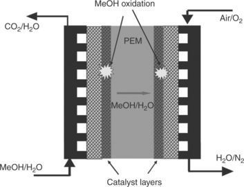
A DMFC is an electrochemical device through which chemical energy can be directly converted into electricity. A schematic of the components that make up a single-cell DMFC is shown in Fig. 11.1. The core of the DMFC is the MEA sandwiched by two flow field plates. The MEA comprises of a proton exchange membrane (PEM), gas diffusion layers (GDLs) and catalyst layers (CLs). A mixture of methanol and water is fed into the anode side of a DMFC, while pure oxygen or air is used as the oxidant at the cathode. The methanol/water and oxygen gas flow through the flow field channels and diffuse through GDLs, respectively, to the anode and cathode CLs.
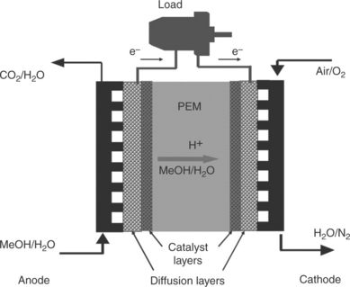
Electrode reaction, energy density and efficiency
The methanol is oxidized on the noble metal catalyst (PtRu) to produce protons, electrons and carbon dioxide (CO2). The protons are conducted from the anode to the cathode through the PEM. The electrons travel from the anode through the external electrical circuit to the cathode, and thereby an electrical current is generated. At the cathode CL, oxygen combines with the protons and the electrons and is reduced on the noble metal catalyst (Pt) to form water.1,2 The reactions that occur in a DMFC are as follows:
For the direct electrochemical oxidation of methanol at the anode, the standard theoretical or ideal potential (EΘ) of the reaction [11.1] can be determined from the changes in Gibbs free energy (∆GΘ) for the reaction according to the known thermodynamic data of all reactants and products under standard conditions:2,3
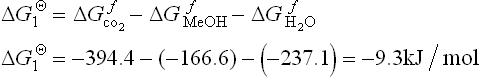
This leads to the standard anode potential:
where n is the number of electrons required to complete the reaction, F is Faraday’s constant (96 485 C/mol), and SHE is the standard hydrogen electrode.
The protons migrate through the PEM and the electrons travel through the external circuit to reach the cathode catalyst layer. At the cathode, electroreduction of oxygen takes place by combining with the protons and electrons. The corresponding change in Gibbs free energy (∆GΘ) and the standard cathode potential for the reaction [11.2] are
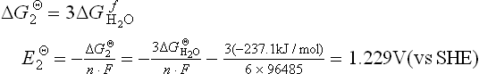
So the equilibrium standard electromotive force for the overall reaction [11.3] can be calculated as
Actually, the open-circuit potential (OCP) of an operating DMFC is much lower than this theoretical potential due to various voltage losses.
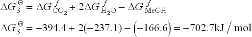
The change in Gibbs free energy (∆GΘ) for the overall reaction [11.3] is
The specific energy can be calculated as
where M is molecular mass of methanol.
Assuming all the Gibbs free energy can convert into electrical energy, and with the enthalpy change ΔH3Θ = −726.7kJ/mol, the theoretical energy efficiency can be calculated as
The energy density of pure methanol is much higher than that of lithiumion batteries (~200 Wh/kg) but quite a bit lower than those of conventional liquid fuels such as gasoline and diesel (~10 000 Wh/kg). The energy efficiency of methanol (97%) is also much higher than that of hydrogen (83%) when used as fuel.4 These significant advantages make the DMFC the most suitable for portable power sources. It can provide longer operation time and more power.
11.2 Historica! development and technical challenges
11.2.1 Historical development of DMFCs
In 1922, the German researcher Müller recognized that methanol was more reactive to produce hydrogen than other hydrocarbons due to the presence of oxygen in methanol. He started the studies on the electro-oxidation of methanol.5 By 1951, on the basis of Müller’s concept, Kordesch and Marko built a DMFC system with carbon electrodes and explored the possibility of using alcohols (ethanol and methanol) as fuels in the alkaline electrolyte of KOH.5 Methanol was reformed to produce hydrogen that was subsequently fed to the fuel cell system. After that, DMFC research made little progress during that decade. In the 1960s, interest in DMFC rose again, aiming at military applications. In 1963, Murray and Grimes at Allis-Chalmers Manufacturing Company developed the first DMFC stack with Pt-Pd anode and Ag cathode catalysts deposited on porous Ni sheet. The stack comprised of 40 unit cells and its maximum power reached 730 W at the voltage of 0.25 V in the 6 M KOH electrolyte and 6 M methanol at 50°C. In addition, they manufactured another DMFC stack that produced 400 W constantly over a period of 5 h at 40°C.5 These achievements opened up new hopes for DMFC research.
In 1965, Williams et al. at Shell Research Limited developed DMFCs based on acid electrolytes that do not react with the CO2 produced from methanol oxidation at the anode.6 Among the different acids, aqueous sulfuric acid was selected due to its higher conductivity and better performance for the oxygen reduction reaction (ORR). Compared to alkaline electrolyte, the water produced at the cathode was easily removed by the air flow to avoid cathode flooding. PtRu and Pt were applied to the surface of a microporous polyvinyl chloride (PVC) substrate as the anode and the cathode, respectively. A gold layer was sputtered on the surface of the PVC to increase the electrical conductivity. A DMFC stack with 40 cells was constructed and it produced 300 W at the voltage of 12 V at 60°C. Although Shell found PtRu to be most effective as methanol oxidation electrocatalyst, the intermediates from methanol oxidation have poisoning effects on the anode catalyst. Also, Tarmy and Ciprios at ESSO Research and Engineering Company developed a DMFC/Air stack for the US Army Electronics Laboratories for a portable military communications system.6 The work started in 1962 and was completed in 1965. The stack used 3.7 M sulfuric acid electrolyte and 0.75 M methanol. The stack temperature and water removal were controlled by the air flow rate. The stack produced 100 W at the voltage of 7 V and demonstrated self-sustaining 60 W at the voltage of 6 V. However, the research on exploring more active catalyst in acid electrolyte was greatly depressed by the slow kinetics of methanol electro-oxidation.
Progress in DMFC technology then almost hibernated until DuPont’s Nafion™ solid-polymer electrolyte membrane was successfully used for the solid-polymer hydrogen/oxygen fuel cell (PEFC) in 1992.6 Around 1994, the Jet Propulsion Laboratory in California demonstrated a Nafion-based DMFC, and a new era of DMFC was initiated.7 The concepts and technology of the PEM fuel cell (PEMFC) were transplanted to the DMFC, and the DMFC and its components were constructed in a manner similar to that of the PEMFC. The OCP and cathode performance were much enhanced as the solid polymer electrolyte membrane reduced the methanol crossover from the anode to the cathode. The methanol fuel could be fed to the anode without getting mixed with the aqueous acid electrolyte.
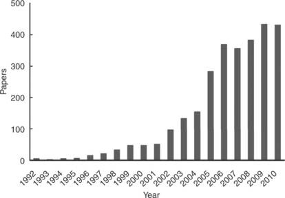
Figure 11.2 shows the number of journal papers published which contain the phrase ‘direct methanol fuel cell’ in the title according to the Web of Science in the period 1992–2010. There are undoubtedly many more papers that may have direct relevance to DMFCs. So the data are not precise, but they give a sense of the high activity in the DMFC area.
11.2.2 Technical challenges presented by DMFCs
Although the DMFC has theoretically high energy density and favorable electrode reaction, in practice DMFC performance is limited by the following factors: the slow kinetics of methanol oxidation due to the poisoning of the catalyst by the intermediates produced, high methanol crossover from the anode to the cathode through the electrolyte membrane, poisoning of the cathode catalyst by methanol, obstruction to methanol flow at the anode by carbon dioxide formation, and obstruction to oxygen flow due to cathode flooding.8
The slow kinetics of both the anode and cathode reactions reduce the cell voltage by 0.4–0.6 V at practical current densities. This has a serious impact on the voltage efficiency of DMFC, which is consequently reduced by up to 50%. During methanol electro-oxidation, various intermediates such as COHads, HCOads and HCOOads are produced and strongly adsorbed on the catalyst surface. The poisoning effect seriously decreases the overall amount of active reaction sites available for methanol oxidation, thus slowing the oxidation reaction. Consequently, the methanol molecules could not be further absorbed on the catalyst surface and be oxidized. Meanwhile, the intermediates absorbed on the catalyst surface could not be oxidized to CO2 and hence reduce the fuel efficiency due to incomplete oxidation. Developing highly active electrocatalysts that inhibit the poisoning is still a challenge facing DMFC research.
Nafion membranes are the commonly used electrolyte membrane and separator in DMFC due to their high proton conductivity and chemical stability. However, methanol permeates through the membrane, dragged by hydronium ions and concentration gradient between anode and cathode, which is called methanol crossover. Methanol reacts directly with oxygen at the cathode as illustrated in Fig. 11.3. Electrons are brought directly from the anode to the cathode along with methanol, resulting in an internal short-circuiting and consequently a loss of current as illustrated in Fig. 11.4.9 This causes not only depolarization effects on the cathode by forming mixed potentials, but also a decrease in the fuel utilization efficiency. Besides, the Pt catalyst at the cathode catalyst is poisoned by intermediates of methanol oxidation in a similar way to the anode. To mitigate the detrimental effect of methanol crossover, low concentration methanol (2–5 wt %) is usually fed to the anode, which reduces the energy density of DMFCs and makes water management more complicated.
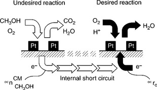
11.4 Cathodic oxygen reduction and undesired methanol oxidation with consecutive charge balance and rate expression. Source: Reprinted with permission from reference 9. Copyright Royal Society of Chemistry.
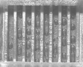
The other major efficiency loss in the electrodes of DMFC is related to mass transport. At the anode, most of the carbon dioxide formed during methanol oxidation is in the gas phase and accumulates in the catalyst layer, diffusion layer and flow field channels.10 There is thus a two-phase flow inside the feed channels due to the small solubility of CO2 in methanol solution. The high amount of CO2 bubbles makes them coalesce and form slugs (Fig. 11.5), which prevent the methanol from diffusing to the catalyst surface and thus result in insufficient supply of methanol. These effects can decrease the voltage of DMFC by 100 mV or more at practical current densities.
11.3 Methanol oxidation reaction catalysts
Electrocatalysts and PEM are key components of DMFC. Promising candidate materials should meet the requirements of high performance, good durability, and low cost for commercialization. The DOE technical targets for 2010 Consumer Electronics are $3/W of cost, 100 W/kg or 100 W/L of power density, and 5000 h of lifetime.11 They have not been achieved with a portable power source of DMFC mainly because of the limitation of current materials.
The state-of-the-art materials of DMFC are PtRu anode catalyst, per-fluorinated membrane (Nafion®), and Pt cathode catalyst. They are all expensive. Further, besides unsatisfactory performance, they are severely subjected to Ru dissolution, methanol crossover, and low methanol tolerance. These problems need to be addressed with new materials or improvement in existing materials to meet the commercial objectives. We examine these issues in the following sections.
11.3.1 Methanol oxidation reaction
Compared with the hydrogen oxidation reaction (HOR) at the anode in a PEMFC, the mechanism of methanol oxidation reaction (MOR) is much more complicated because it involves six electrons to transfer and more intermediates. Figure 11.6 shows a proposed reaction network for MOR, involving all possible intermediates and reaction paths,12 where * denotes a catalytically active site. It needs to be mentioned that formaldehyde and formic acid are two stable intermediates and can be treated as byproducts. To guide the design of catalysts for MOR, the favorite pathways, that is, the minimal energy paths, and the rate determining step (RDS) need to be fully understood. Intensive research in this area has led to the conclusion that the favorite pathway depends on the catalyst, the electrolyte and the reaction conditions (e.g., the potential). However, the mechanisms of the catalysis of MOR are still far from fully understood.
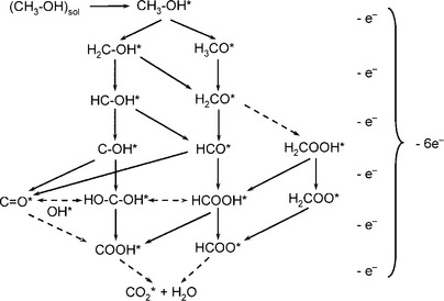
The mechanisms of MOR can be classified into two types:12 (1) an indirect mechanism that goes through a CO intermediate and its subsequent oxidation to CO2 and (2) a direct mechanism where methanol is oxidized to CO2 without the formation of the CO intermediate. Density-functional theory (DFT) calculations have shown that the catalyst performance for the direct and indirect mechanisms can be characterized by two reactivity descriptors: the adsorption free energies of OH* (GOH*) and CO* (GCO*) on the active sites. For a catalyst preferred for indirect mechanism, for example Pt, the performance can be enhanced by decreasing the GCO*.
11.3.2 Pt-based catalysts
As shown in Fig. 11.6, MOR involves the reactions of deprotonation and combination of intermediates with OH* to finally produce CO2. Pt is one of the most efficient catalysts for deprotonation reactions in acidic media and thus was used for MOR in DMFC at first. It is either unsupported (Pt black, 10–20 nm) or supported on high surface area carbon black (Pt/C, 3–5 nm Pt nanoparticles on 50 nm carbon black). The main advantage of using Pt/C is the high efficacy of Pt usage due to the high dispersion of Pt nanoparticles. Because methanol solution is a liquid phase under DMFC operating conditions, the MOR is subjected to larger mass transport resistance than the HOR at the anode in PEMFC. The advantage of using Pt black is to lower the mass transport resistance with a thinner anode catalyst layer. Using a Pt/C with high metal loading is a trade-off between the efficiency and mass transport resistance. This is applicable for other non-platinum catalysts as well. To date, 60wt. % metal loading is the highest for commercial Pt/C used in DMFC.
The mechanisms of MOR on Pt in acidic media have been investigated intensively. It has been concluded that it mainly takes indirect paths which proceed via the formation of CO. The RDS is the combination of CO* with OH* because the CO* is too strongly adsorbed on Pt which inhibits the consequential desorption and further adsorption. This combination rate is significantly lower at potentials less than 0.6 V (vs SHE) over Pt(111), where CO is strongly chemisorbed and inhibits oxidation. Besides, the production of OH* from the dissociation of water on Pt only takes place at a remarkable rate when the potential is higher than 0.45–0.5 V (vs SHE). Both cause insufficient activity of Pt toward MOR and are not commercially useful for DMFC.
An intensive search for more active materials has been conducted over the years. They should have the ability to simultaneously adsorb methanol and water at low potentials, and thus allow for the oxidation of methanol at low overpotential.13 Because Pt is still one of the most efficient catalysts for the sequential deprotonation of methanol in an acidic medium, the search has focused on the addition of a secondary material, such as metals and oxides.
Binary Pt–metal catalysts
A second metal, such as Ru,14–17 Rh,18 Re,19 Co,20 Ni,21 Mo,22 Sn,23–25 Au,26 Cu27 and W,27 has been added to form binary Pt alloys or bimetallic catalysts to enhance the activity toward MOR. These metals are known/supposed to form surface oxide species that could promote MOR by providing OH*. Among them, Pt–Ru bimetallic or alloy catalysts are known to be more active than Pt or other Pt-based binary catalysts for MOR.14–17 It is the state-of-the-art anode catalyst and commonly used for DMFC.18 The preparation methods, composition and support effect, etc., have been well discussed and reviewed.28
The enhanced activity of PtRu toward MOR has been widely accepted to be due to the bifunctional or synergistic effect of Pt and Ru: that is, methanol dissociative adsorption takes place at the Pt active site, and Ru dissociates/discharges water molecules to supply OH through Ru–OH (which promotes the formation of Pt–(OH)ads) to combine with CO* on Pt. CO stripping voltammograms showed that the Pt–Ru catalysts have a lower overpotential for CO oxidation, which means the CO is easily removed on catalysts leading to higher activity toward MOR. This proposed effect was directly observed through the use of a scanning tunneling microscope.29 This enhancement mechanism requires the Pt and Ru sites to be adjacent or in clusters. The water discharging with the formation of Ru–OH groups is possible at considerably lower electrode potential (0.2 V vs SHE)30 and more effectively at high potentials (above 0.45 V vs SHE)31,32 This means that there is still space for improvement if the water discharge can happen at high rate at lower potential.
However, the PtRu anode catalysts are subjected to Ru dissolution because Ru is less noble than Pt and undergoes oxidation with water in acidic acid starting around 0.4 V (vs SHE). It causes the performance degradation in DMFC33,34 not only by diminishing the MOR activity of the anode catalyst but also by imposing a Ru contamination on the Pt cathode catalyst toward ORR, since a migration of the dissolved Ru from the anode to the cathode through the membrane blocks the active Pt sites at the cathode. It has been reported that the Ru contamination decreases the oxygen reduction kinetics by eight fold or increases the overpotential by about 160 mV.35
Binary Pt–metal oxide catalysts
Transition metal oxides with a capability to supply OH and also stable in acid, such as WO3,36 CeO2,37–40 and SnO2,41 have been pursued as a secondary material incorporated with Pt as anode catalysts to enhance the MOR.42 For instance, CeO2 not only has high oxygen carrying capacity, that is, storage and release of oxygen at low temperature via a redox process reversibly between Ce4+ and Ce3+,37–40 but also is stable under acidic conditions. It promotes methanol oxidation on Pt by supplying oxygenic species at lower potentials, as Ru does in PtRu. Unlike PtRu/C, where the Pt and Ru form an alloy phase with an atomic-scale mixing, Pt–oxide/C consists of a composite of Pt and oxide particles. Therefore, the promoted MOR is limited on the Pt particles that are in intimate contact with both the oxide and the carbon support, respectively, for the supply of oxygenic species and electrical conduction. Thus, the control of the particle morphology is critical to maximize the catalytic activity of Pt–oxide/C. The challenge with the synthesis is to guarantee an intimate contact of Pt with both the oxide and carbon and high dispersion. A desired particle morphology of Pt–CeO2/C is shown in Fig. 11.7.43 A one-step, controlled reverse microemulsion (RME) method has been successful in overcoming this challenge.42
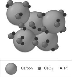
11.7 Schematic diagram of ideal Pt–CeO2 /C with an intimate contact between Pt and CeO2 nanoparticles. Source: Reprinted with permission from reference 43. Copyright American Chemical Society.
It needs to be remarked that ternary44–50 or even quaternary51,52 Pt-based catalysts have been prepared with higher activity than Pt and even Pt–Ru catalysts. However, a significant improvement in performance needs to be realized to compensate for the complications involved in the synthesis.
11.3.3 Other catalysts
To reduce the cost, Pt needs to be replaced by non-noble materials. To date, there are limited publications on non-platinum catalysts for MOR in acidic media because even Pt, the best deprotonation catalyst, still has low performance toward MOR. The performances of non-platinum catalysts, such as dispersed gold nanoparticles onto a conductive polymer (polyaniline) grafted multiwall carbon nanotube (MWNT-g-PANI) matrix53 and metal-free carbon nitride nanotubes,54 are much lower than that of Pt catalysts. Therefore, very limited comparison of MEA performances has been reported.41 For these low-cost catalysts, a trade-off must be made between performance, durability and cost for practical use.
11.4 Oxygen reduction reaction (ORR) catalysts
11.4.1 ORR with methanol tolerance
The ORR is known to have sluggish reaction kinetics. Even the state-of-the-art Pt catalysts toward ORR lead to a loss of ~ 400 mV at the cathode in PEMFC. This loss becomes even higher at the cathode of a DMFC due to the poisoning of and ‘mixed potential’55 on the Pt catalysts by the methanol, which crosses over from the anode to the cathode through the Nafion membrane. The methanol oxidation on the cathode catalyst (Pt catalysts) produces CO intermediates, which strongly adsorbs on the Pt surface to block the active sites for ORR, known as poisoning. Besides, the MOR current at the cathode needs neutralization from the ORR current. A certain value of overpotential required to generate this amount of ORR current is known as ‘mixed potential’. It is thus apparent that a good cathode catalyst should be more selective toward the ORR to minimize the ‘mixed potential’ and should not be poisoned by the CO intermediate from MOR (termed methanol tolerance). The requirement of both good catalytic activity toward ORR and high methanol tolerance makes it much more challenging to design a cathode catalyst for DMFC than for PEMFC.
First of all, a comprehensive understanding of the mechanisms of ORR is needed. Despite the significant advances over the years, ORR promoted on the surface of a catalyst in acidic media is still not fully understood. The ORR involves three intermediates: O*, OOH* and OH*, where the * denotes a catalytically active site. The possible pathways for ORR are indicated in Fig. 11.8. Of all the pathways, (1) is the least probable because of the higher energy barrier for O2 dissociation. H2O and H2O2 are the products, respectively, following the four-electron and two-electron mechanisms. Two types of four-electron mechanism have been proposed in the literature: mono-site mechanisms following the pathways 2, 3, 6, and 7 and dual-site mechanisms following the pathways 2, 4, 6, and 7.56 The two-electron mechanism follows pathways 2 and 5 to produce H2 O2. For maximum current efficiency, the four-electron mechanisms are desired and the two-electron mechanisms need to be suppressed.
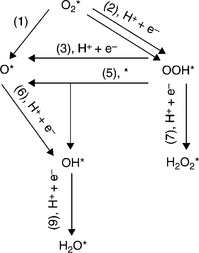
It has been concluded that the RDS involves the removal of O* and OH* for the mono site mechanisms, and the rupture of the O–O bond for the dual site mechanism. The enhancement of ORR catalysts can be approached by effectively increasing the rate of the RDS in various ways such as altering the surface chemistry, electronic structure, and lattice parameter. All these approaches should not increase the activity toward MOR and the bonding between the catalysts and the intermediate of CO.
11.4.2 Pt-based catalysts
Enhancement of ORRs
The state-of-the-art Pt catalysts toward ORR lead to a loss of ~ 400 mV. It has been reported that addition of less expensive transition metals or metal oxides suppresses this loss, offering higher catalytic activity than Pt while lowering the cost.57–66 It needs to be remarked that special materials and/or special synthesis methods are often involved, resulting in additional costs and difficulty of mass production. Additionally, the dissolution of non-noble metal components and the consequent performance loss during cell operation remain a big concern.30,67,68
First, the formation of a passive and insulating Pt oxide layer on the catalyst at high potential could contribute to a major portion of the high overpotential of the Pt catalyst toward ORR. This Pt oxide formation has been identified with a reduced Tafel slope at high potentials69 and also confirmed with differential electrochemical mass spectrometry.70 It has been concluded that the oxides start to form on the Pt surface at a potential of ca. 0.8 V and then reach a monolayer at ca. 1.1 V. Inhibition of this oxide film may be the most effective way to reduce the large overpotential of the ORR. This decrease in active sites at high potential can be suppressed by altering the surface chemistry. It can be achieved by the addition of a metal or metal oxide with stronger OH or O affinity, that is, higher negative free energy change for oxidation. Several studies have shown that Pt alloys with first-row transition metals, such as Cr, Co, Ni and Fe, have a constant Tafel slope of 120 mV/dec, indicating that the Pt oxide formation is inhibited or shifted to a more positive potential.69
Additionally, changes to the d-band structure have been proposed as a way to decrease the ORR overpotential by finding optimal intermediate adsorption energies. According to the Sabatier principle, the adsorption energy between the catalyst and the adsorbed species must have an optimum value resulting in a so-called volcano-type relationship. It has been realized that the adsorbed species OH is too strongly adsorbed on Pt. Decreasing the affinity of Pt for OH can, therefore, enhance the ORR by freeing active sites. This can be achieved by adjusting the electronic structure, slightly decreasing the d-band center of Pt though ensemble and ligand effects.71–75 Using DFT, Ruban and co-workers72 have attributed the decrease in the d-band center to the compression of an overlayer on a smaller metal substrate, termed as the ensemble effect. Also, using DFT, Kitchin and co-workers73 have found that Pt(111) surfaces modified by subsurface 3d transition metals enhance the activity through metal-metal interaction, termed as ligand effect. They also found that a combination of the ensemble and ligand effects changes the electronic and surface properties of Ni, Pd and Pt monolayers on substrates of other metals, a kind of core-shell structure.75 The d-band model is a useful tool for understanding the relationship between adsorbed species and transition metals and is, therefore, critical to explaining enhancement of the ORR on alloy and core-shell catalysts.
Enhancement of methanol tolerance
Although the enhancement of ORR for Pt-based catalysts has been intensively investigated, the enhancement of methanol tolerance is far from satisfied. The reason is that Pt has rather good catalytic activity toward MOR and strong bonding with the CO intermediate. Non-platinum catalysts should be searched especially for DMFC operating with high concentration of methanol.
11.4.3 Pd-based catalysts
In addition to the poor methanol tolerance, Pt is expensive and there is not enough mining capacity to support a widespread commercialization of the fuel cell technology. There is enormous interest in developing alternative less expensive and high methanol-tolerant catalysts as well as in lowering the Pt loading to realize commercially viable DMFCs.58,76–82
Pd has the best ORR performance except Pt in acidic media among all pure metals. It has lower cost, higher mining capacity and lower activity toward MOR in comparison with Pt, making it a very attractive cathode catalyst for DMFC. The target for designing Pd-based catalysts is to improve its ORR catalytic activity without increasing the activity toward MOR, as well as to improve its durability. Similar to Pt, the activity of Pd toward ORR can be enhanced by inhibiting oxide formation and adjusting the d-band center and shape. Alloying of palladium with other inexpensive metals like Co, Mo, Ti, Cu, etc., offers higher ORR activity and additional cost reduction. Figure 11.9 shows that the Pd70Co30 and Pd70Co20Mo10 catalysts maintain the Tafel slope at high potential while Pd has a reduced Tafel slope as pure Pt does. The enhancement in activity is attributed to the suppression of Pd oxide formation. It has been found that Pd is inclined to segregate onto the surface while Co is rich inside. The Pd surface forms a protective layer, while Co modifies the electronic properties of Pd, making the ‘d-band center’ mimic the d-band of the Pt or Pt-M with high ORR performance. Similarly, PdCu/C is another binary Pd-based catalyst with promoted catalytic activity toward ORR with higher MOR tolerance.
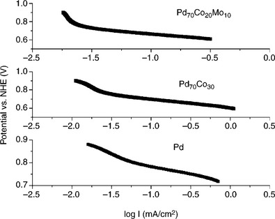
11.9 Linear polarization data collected with various Pd-based catalysts in 0.5 M H2SO4 at a scan rate of 5 mV/s.
Enhancement of methanol tolerance
The tolerance of the cathode catalyst to methanol at the cathode is an important parameter to achieve good cell performance and operational life in DMFC. Pd-based alloy catalysts exhibit high tolerance to MOR with good catalytic activity. Figure 11.10 compares the potential loss for the Pd70Co20Mo10 and commercial Pt catalysts at various methanol concentrations and current densities. The Pt catalyst exhibits a significant potential loss as the methanol concentration increases, while the Pd70Co20Mo10 catalyst exhibits quite stable performance with only a small potential loss at high methanol concentrations, indicating remarkable tolerance to methanol. Additionally, the potential loss observed for the Pt catalyst is higher at lower current densities, indicating that the methanol poisoning is significant in the activation over-potential region of the oxygen reduction kinetics.82
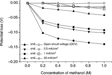
11.10 Comparison of the potential loss due to methanol poisoning at various methanol concentrations in 1.0 M H2SO4 at different current densities. Closed and open symbols refer, respectively, to commercial (Johnson-Matthey) Pt catalyst and 500°C-annealed Pd70Co20 Mo10 catalyst. The metal loading in the electrode was 0.2 mg/cm2. Source: Reprinted with permission from reference 83. Copyright American Chemical Society.
Enhancement of durability
For practical applications, in addition to high catalytic activity, good chemical stability of the catalysts in the fuel cell environment is essential. The greatest challenge for Pd-based catalysts is how to mitigate the Pd dissolution. Pd is less stable than Pt and undergoes remarkable electrochemical oxidation at the cathode, leading to severe Pd dissolution. The Pd/C and Pd100 – xCox catalysts were found to exhibit a decrease in activity as they are cycled, indicating a chemical instability. In order to improve the chemical stability, a few binary and ternary alloy catalysts such as Pd50Ti50, Pd70Co20Mo10, Pd70Co20W10, and Pd70Co20Au10 have been investigated.83–85
Initial stability assessment with cyclic voltammograms in 0.5 M H2SO4 indicated that while Pd70Co20Au10 exhibits chemical instability like Pd70Co30, compositions like Pd50Ti50, Pd70Co20Mo10 and Pd70Co20W10 exhibit excellent chemical stability. Figure 11.11 compares the polarization curves recorded before and after polarizing at 200 mA/cm2 in single cells fabricated with these catalysts.83 While the cell with the Pd70Co20Au10 catalyst shows a degradation in performance after polarizing, both Pd70Co20Mo10 and Pd50Ti50 exhibit excellent chemical stability without any noticeable degradation in performance. Figure 11.12 shows the performance of the Pd70Co20Mo10 catalyst for ORR in PEMFC for 200 h at a constant current density of 300 mA/cm2. The data reveal excellent long-term chemical stability without any degradation.
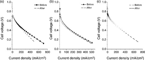
11.11 Comparison of the steady-state polarization curves of the carbonsupported catalysts: (a) 750°C-heated Pd70Co20Au10, (b) 900°C-heated Pd50Ti50 and (c) 500°C-heated Pd70Co20Mo10 for ORR in single-cell PEMFC at 60°C with Nafion 115 membrane and a cathode loading of 0.2 mg/cm2 before and after polarizing the cell at 200 mA/cm 2 for 12 h in (a) and (b) and for 80 h in (c). Source: (a) and (b) reprinted with permission from reference 84. Copyright American Chemical Society; (c) reprinted with permission from reference 83. Copyright American Chemical Society.
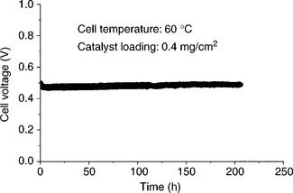
11.12 Evaluation of the stability of the Pd70Co20Mo10 catalyst in PEMFC at 60°C. The MEA was fabricated with Nafion 115 membrane and an anode and cathode loadings of 0.4 mg/cm2.
Although the reason for the differences in stability between, for example, Pd70Co20Mo10 and Pd70Co20Au10 are not fully understood, we believe that the enrichment of the surface by Mo and its oxides in the Pd–Co–Mo system and Ti and its oxides in the Pd–Ti system may be the reason for the better stability. A better understanding of the factors influencing the stability needs to be developed.
11.4.4 Other catalysts
Besides the most promising Pd-based catalysts,86–88 alternative electrocatalysts with good methanol tolerance such as non-platinum-based metal combinations, 89–92 metal oxides, 93–95 metal carbides, 96 metal porphyrins, chalcogenides 97,98 (ruthenium-based chalcogenides, 99,100 chalcoginides such as RuSe, 58,96,99–101 and pyrolyzed transition metal N 4 chelates 59,60,63,64,101), enzymes, 102 inorganic and organometallic complexes including porphyrins 102–105 have been investigated over the years for ORR to reduce the cost.
Although tremendous progress in improving the activity and stability of non-platinum cathode catalysts such as heat treated macrocyclic compounds of transition metals106–109 and ruthenium-based chalcogenides86–88,110–114 has been achieved, they still exhibit lower catalytic activity toward ORR and lower stability than Pt catalysts in the absence of methanol. However, when methanol is present, the decrease in performance with the methanol-tolerant catalysts is much lower than that with Pt electrodes. Overall, their activity and stability need further improvement.
11.5 Proton exchange membranes
PEMs play a critical role in the performance as well as long-term stability of DMFCs. Although varying depending on the applications, common requirements of a PEM in a DMFC include: (i) high proton conductivity, (ii) high chemical and mechanical stability, (iii) low permeability of fuels and oxidants through the membrane, (iv) good durability and (v) low cost. In addition, a low ruthenium crossover is also required for DMFC where PtRu alloy is used as the anode catalyst.
11.5.1 Perfluorosulfonic acid (PFSA) membranes
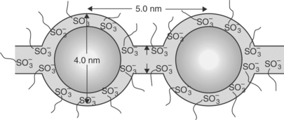
Much effort has been devoted to the research and development of perfluorosulfonic acid (PFSA) membranes such as Nafion (Dupont), Aciplex (Asahi Chemical company), Flemion (Asahi Glass Company) and XUS (Dow Chemical) due to their high proton conductivity and good chemical stability resulting in good performance and durability. The chemical structures of some PFSA membranes are shown in Fig. 11.13. Nafion is the most investigated PFSA membrane and widely used as the electrolyte membrane in PEMFC and DMFC. The proton and water transport properties of Nafion could be well explained by the cluster-network model shown in Fig. 11.14 based on the small-angle X-ray scattering (SAXS) and wide-angle X-ray diffraction (WAXD) studies. The hydrophobic polytetrafluoroethylene (PTFE) backbone of PFSA polymers provides thermal and chemical stability and forms a hydrophobic crystal region, while the perfluorinated side chains terminating with the hydrophilic sulfonic acid groups (− SO3H) form a hydrophilic region (clusters and channels). The clusters formed by the absorbed water and side chains are around 4 nm wide, which are periodically arranged among the hydrophobic region. The distance between the clusters is around 5.0 nm, and the clusters are connected by channels with a diameter of 1 nm.
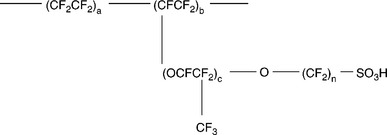
11.13 Chemical structures of perfluorosulfonic acid membranes. Nafion: a = 6–10, b = 1, c = 1, n = 2. Aciplex: a = 6–8, b = 0–1, c = 1 (0–2), n = 2–5. Flemion: a = 6–10, b = 1, c = 1, n = 2.
Despite the obvious advantages of the perfluorinated membranes, there are a few disadvantages when applying them in DMFCs:
• High methanol crossover: This is due to the transport of methanol from the anode to the cathode through the membrane by diffusion and electroosmoitc drag. The methanol permeability not only wastes the fuel but also leads to an undesired reaction at the cathode platinum catalyst, resulting in a severely reduced overall cell performance. The poisoning of the cathode catalyst by methanol necessitates higher Pt catalyst loading on the cathode, resulting in a higher cost of DMFC.
• Low operating temperature: Nafion membrane is required to be fully hydrated to maintain high proton conductivity during cell operation. The proton conductivity of Nafion membrane decreases dramatically when the water content decreases in the membrane. So the operating temperature of DMFC is limited to < 100°C at ambient pressure. When cell is operated at > 120°C, the poisoning effect of CO on the Pt catalyst is minimized and activity toward methanol oxidation is greatly improved.
• High cost: The price of perfluorinated membrane is as high as $600/m2, which contributes significantly to the overall cost of DMFC.
Among these disadvantages, methanol crossover in perfluorinated membranes is the critical issue with respect to achieving higher fuel and power efficiency. It is also an unavoidable issue as long as the electrolyte membrane requires water for proton conduction. Generally, two major strategies are employed in the literature to minimize methanol crossover. The first one is to modify the existing perfluorinated membrane to offer higher proton conductivity and lower methanol crossover. The second one is to design and develop novel non-fluoropolymer materials.
11.5.2 Modification of Nafion® membranes
Silica-modified Nafion®
Modification of the existing Nafion membranes is an effective strategy to lower methanol crossover in DMFC. The modification is mainly focused on changing the distribution of the clusters in Nafion by incorporating or blending it with other inorganic/organic additives. Incorporation of organic Si-based or inorganic silica additives into Nafion membrane is a widely used approach to modify Nafion membrane for DMFC applications. Nafionsilica membranes have been prepared by solution casting of mixtures of a Si source and Nafion solutions. The nano-sized silica particles in the cast membranes can effectively block the permeation of methanol through the membrane.115–117
Cs+-doped Nafion®
The proton and methanol transport phenomena in Cs-doped Nafion membranes were studied by Tricoli.118 The cesium-doped Nafion membranes were found to be highly impermeable to methanol. Also, the methanol permeability in the membrane was reduced by one order of magnitude due to the presence of cesium ion. The partially doped membranes retained good proton conductivity as well.
Metal-impregnated Nafion®
Jiang et al.119 reported that impregnating Pd nanoparticles into Nafion membrane could lower methanol crossover, resulting in increased fuel efficiency and deceased cathode catalyst poisoning. Jung et al.120 also studied PtRu-doped Nafion in DMFC, and it was found that a small amount of PtRu in Nafion acts as a methanol barrier through the chemical oxidation of methanol on PtRu particles in the membrane, which helps to lower methanol crossover. However, the proton conductivity of the metal-impregnated Nafion membranes decreased with increasing amount of impregnated metal particles.
Polymer-composite Nafion® membranes
Polymers such as polyfurfuryl alcohol (PFA),121 poly(vinylalcohol) (PVA),122 polypyrrole123 and poly (3,4-ethylenedioxythiophene) (PEDO)123,124 have been chemically and electrochemically added to Nafion to form blend membranes. The resulting polymer composite membranes have been studied by methanol permeability and proton conductivity measurements. The presence of polymers in the cluster destroys the distribution of sulfonic acid groups and blocks methanol crossover through the membrane. But it also blocks the proton conduction channels in the membrane, resulting in a decrease in the proton conductivity of the membranes.
Surface modification ofNafion®
By applying a plasma or an electron beam,125 the surface structure of Nafion membrane can be changed. A thin methanol barrier layer on the surface was created after the modification, resulting in a much suppressed methanol crossover and up to 50% increase in the power output in DMFC compared to the use of plain Nafion membrane.
Although these approaches could reduce methanol crossover, they generally tend to decrease proton conductivity and sometimes lead to a loss in mechanical strength. In view of this, there has been considerable interest to develop new membrane materials that can suppress methanol crossover while offering acceptable proton conductivity.
11.5.3 Polytetrafluoroethylene (PTFE)-reinforced composite membranes
PTFE is selected as a reinforcing material for its excellent chemical stability and good mechanical strength. The reinforced membrane comprising of expanded PTFE porous sheet and a perfluorinated ionomer was first developed by W.L. Gore & Associates in the 1990s, which has been commercialized as Gore-select® and has been widely used for PEMFC systems. The PTFE-reinforced membrane contains much lower amount of the expensive perfluorinated ionomer than the traditional perfluorinated membranes such as the Nafion series membrane, thus the cost of the composite membranes is much lower. The composite membranes also offer other advantages such as excellent mechanical and chemical stability and thinner thickness. Lin et al.126 found both methanol diffusion and methanol electro-osmosis crossover in PTFE/Nafion composite membrane were reduced, thus giving better cell performance. But it has higher proton resistance compared to the Nafion membrane. Zirconium phosphate was then introduced to modify PTFE/Nafion membrane to further reduce methanol crossover rate and enhance proton conductivity.127
11.5.4 Sulfonated aromatic polymer membranes
Among the various polymer materials being investigated, sulfonated aromatic polymers show promising features for possible applications in DMFC. For example, sulfonated polyimide (SPI),128 sulfonated polyphenylene (SPPO),129 sulfonated polysulfone (SPSf),130 sulfonated poly(ethersulfone) (SPES)131 and sulfonated poly(ether ether ketone) (SPEEK)132 are actively being investigated as candidates to substitute for the PFSA membranes in DMFC. The structures of some of these sulfonated polymer materials are shown in Fig. 11.15. The aromatic polymers are non-fluorinated polymers with high glass transition temperature, high thermal stability, good mechanical properties, excellent resistance to hydrolysis and oxidation and lower cost.
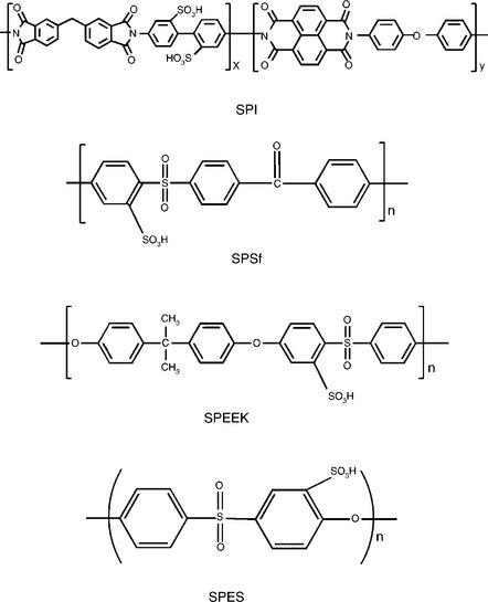
11.15 Chemical structures of some sulfonated polymers. SPI: sulfonated polyimide; SPSf: sulfonated polysulfone; SPEEK: sulfonated poly(ether ether ketone); SPES: sulfonated poly(ethersulfone).
Sulfonated aromatic polymers could be synthesized through polymerization reactions from different monomers bearing sulfonic acid groups. With this strategy, several PEM with controllable chemical structures (degree of sulfonation and sulfonation sites) and well-refined microstructure have been investigated, for example, sulfonated polyimide (SPI),128 sulfonated polyphenylene (SPPO),129 sulfonated poly(aryl ether)s (SPAEs)133 and sulfonated poly(ether ketone) (SPEK).134 By changing the monomers used in the polymerization reactions, the properties of the product polymers could be tuned, and some fundamental understanding of the structure-property-performance relationships have been achieved. Introduction of sulfonic acid groups to these polymers are performed in several ways as follows: (1) direct sulfonation in concentrated sulfuric acid or chlorosulfonic acid, (2) radiation-grafting of monomers onto the polymer backbone followed by sulfonation, (3) synthesis from monomers bearing sulfonic acid groups, and (4) lithiation-sulfonation-oxidation. The properties of these sulfonated polymers are mainly controlled by the degree of sulfonation (DS). The DS could be controlled by the reaction time, temperature and amount of sulfonating agent used in the reaction. Table 11.1 summarizes the IEC, DS, and water uptake at 80°C for SPEEK membranes.132
Table 11.1
Ion exchange capacity (IEC), degree of sulfonation (DS), and water uptake of SPEEK membranes obtained with different sulfonation reaction times
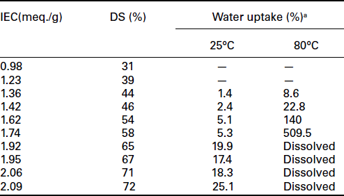
aMembranes could not be prepared for low sulfonation levels due to the limited solubility of the membranes in the N,N– dimethylacetamide solvent.
Source: From reference 132.
Usually, the sulfonated aromatic polymers show lower methanol cross-over than the fluorinated membranes due to their more rigid backbone compared to the PTFE backbone in the Nafion type membranes.132 Using sulfonated polyetherketone (SPEEKK) as an example, based on the SAXS data and a cubic hydrophilic channel system in a hydrophobic matrix, a model for the microstructure has been proposed and compared with that of Nafion membrane (Fig. 11.16).135 The water-filled channels in SPEEKK are narrower compared to those in Nafion. They are less separated and they have larger hydrophilic/hydrophobic interface (larger average separation of neighboring sulfonic acid functional groups). The stronger confinement of the water in the narrow channels of the aromatic polymers leads to a significantly lower dielectric constant of the water of hydration, leading to much lower methanol crossover than in Nafion membrane. In addition, the pKa value of the sulfonic acid in sulfonated PEEK is around − 1, which is much higher than that of the Nafion membrane (pKa ~ −6), leading to lower proton conductivity and usually lower fuel cell performance. In order to maximize the proton conductivity, a high degree of sulfonation (DS) is desired, which often leads to an increase in membrane swelling and degradation in mechanical stability.
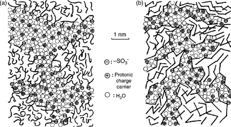
11.16 Schematic representation of the microstructures of (a) Nafion and (b) sulfonated poly(ether ether ketone) (SPEEK). Source: Reprinted with permission from reference 135. Copyright Elsevier.
The proton conductivity, water swelling, methanol permeability and DMFC performance of these membranes have been investigated.
11.5.5 Cross-linked polymer membranes
Various strategies have been investigated in order to reduce the swelling of the sulfonated polymers with high DS. Covalent/ionic cross-linking is found to be an effective way to control the dimensional stability and suppress methanol crossover of the PEM without sacrificing the proton conductivity too much. Recently, covalent cross-linked sulfonated aromatic polymers with high DS have been reported.136–138 For example, Vona et al.138 studied the properties of the covalent cross-linked SPEEK with high DS (Fig. 11.17), and the resulting membrane showed much better swelling stability and lower methanol permeability compared to the uncross-linked polymers. Usually, the thermal stability of these covalently cross-linked polymers is quite high (230–270°C). However, the polymers with covalent cross-linking become brittle after drying, which is a critical problem for fuel cell applications. The brittleness is possibly caused by the inflexibility of the covalent networks. Because of this reason, more and more attention is being paid to the development of ionomer networks containing ionic cross-links that are more flexible.
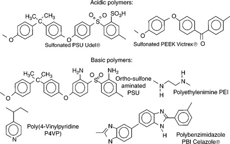
Ionic cross-linked membranes were first investigated with anhydrous polymeric proton conductors like polybenzimidazole (PBI).139,140 Unlike the polymers containing sulfonic acid groups, the nitrogen sites on the heterocycles in PBI act as proton donors and acceptors, which facilitates the proton transfer through a Grotthuss-type mechanism.141 Due to the slow rate of the proton transfer facilitated by the Grotthuss-type mechanism at low temperature, usually the operation temperature of these kinds of membranes is higher than that of sulfonated polymers. In 1995, Wainright et al.142,143 first proposed a blend of PBI and phosphoric acid as the electrolyte for PEMFCs and DMFCs. The intrinsic property of phosphoric acid and ease in preparing the blends with a large variety of polymers drew more and more attention after this investigation. In this type of acid-doped PBI membranes, nitrogen sites on the heterocycles exhibit basic properties, and they are also termed as acid–base blend membranes. The strong acid–base interactions and the hydrophobicity of the basic polymers could promote proton conduction and block methanol permeation through the membrane. Based on this approach, Schauer’s group144 has studied the acid–base blend membranes consisting of SPPO/PBI, which showed good thermal stability and flexibility as PEM in fuel cells. Kerres’ group145,146 reported several ionic cross-linked blend membrane systems based on acid–base interactions as shown in Fig. 11.18 (e.g., sulfonated polysulfone (SPSf)/aminated PSf and SPEEK/PBI). All the blend membranes exhibit good flexibility, thermal stability and lower methanol permeability in DMFCs. However, the dimensional stability at T > 70°C is inadequate with some of the blend membranes.
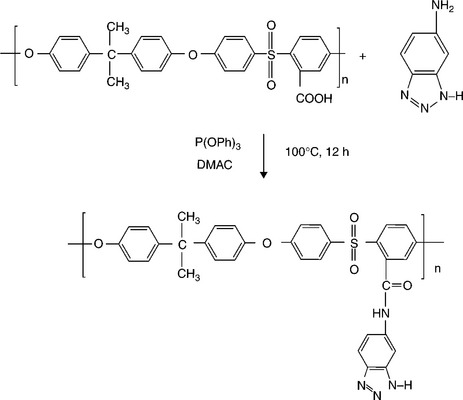
Our group147,148 reported recently that blend membranes based on acid–base interactions between the sulfonic acid groups of SPEEK and the N-heterocycle groups tethered to polysulfone show suppressed methanol crossover and enhanced performance in DMFC. This blend membrane concept is based on industrially available, inexpensive polymer precursors like poly (ether ether ketone) (PEEK) and polysulfone (PSf) that are compatible with each other due to similar aromatic backbones. A series of heterocycle-tethered basic polymers such as polysulfone-bearing 4-nitro-benzimidazole (PSf-NBIm), polysulfone-bearing 1H-Perimidine (PSf-PImd), and polysulfone-bearing 5-amino-benzotriazole (PSf-BTraz)) have been synthesized and characterized. Blend membranes consisting of sulfonated poly (ether ether ketone) (SPEEK) and different basic polymers have been investigated by measuring proton conductivity, liquid uptake, ion-exchange capacity, and electrochemical performance and methanol crossover in DMFC.149,150
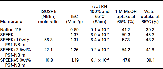
The synthesis scheme for polysulfone-bearing 4-nitro-benzimidazole (PSf-NBIm), and 5-amino-benzotriazole (PSf-BTraz)) are shown in Figs. 11.19 and 11.20, respectively. Table 11.2 gives the ion-exchange capacity (IEC) values, proton conductivity values, water uptake and methanol uptake values measured under 100% RH at 65°C for various contents of PSf-NBIm in the SPEEK/PSf-NBIm blend membranes. It can be seen that the IEC values of the blend membranes are lower than that of plain SPEEK, indicating the occurrence of acid–base interactions in the blend membranes and the consequent reduction in the amount of H+ ions dissociating from the sulfonic acid groups. Moreover, the IEC value decreases as the PSf–NBIm content increases due to an increase in the degree of acid–base interaction, while the blend membrane with 2.5 and 5.0 wt% PSf–NBIm shows higher proton conductivity than plain SPEEK membrane. The increase in proton conductivity is due to the assistance of proton transfer by the nitro-benzimidazole groups in PSf–NBIm through the acid–base interactions as illustrated in Fig. 11.21. The sulfonic acid groups of SPEEK can protonate the nitrogen site of nitro-benzimidazole, facilitating the hopping of the proton bound to the other nitrogen of the nitro-benzimidazole unit to the oxygen of another sulfonate anion group.
Table 11.2
Ion-exchange capacity (IEC), proton conductivity (σ), water uptake and MeOH uptake of Nafion 115, plain SPEEK and SPEEK/PSf–NBIm blend membranes with various [–SO3H]/[NBIm] mole ratio
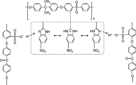
11.21 Illustration of the proton transfer mechanism involving acid–base interactions in the SPEEK/PSf–NBIm blend membrane.
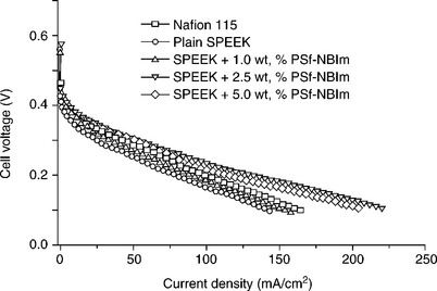
Table 11.2 also compares the percent liquid uptake in water and in 1.0 M methanol solution for various PSf-NBIm contents of the SPEEK/ PSf-NBIm blend membranes. The liquid uptake decreases with increasing PSf-NBIm content at a given temperature or methanol concentration. The lower liquid uptake of the SPEEK/PSf-NBIm blend membrane is believed to be due to the increase in both the hydrophobicity of PSf-NBIm and the acid–base interaction between and sulfonic acid and nitro-benzimidazole groups in the blend membrane. The lower liquid uptake could also help to lower the methanol crossover in DMFCs. Figure 11.22 compares the polarization curves of the SPEEK/PSf-NBIm blend membranes containing various PSf-NBIm contents (1.0-5.0 wt%) with those of plain SPEEK and Nafion 115 membranes at 65°C. The SPEEK/PSf-NBIm blend membranes show higher fuel cell performance than plain SPEEK membrane, which is consistent with the higher proton conductivity values seen in Table 11.2. More importantly, although the plain SPEEK membrane shows lower performance than Nafion 115 membrane due to the lower proton conductivity, the SPEEK/PSf-NBIm blend membranes with PSf-NBIm contents of 2.5 and 5.0 wt% exhibit higher performance than Nafion 115, confirming the assistance of PSf-NBIm in enhancing the proton conduction. The higher performance is also due to the lower methanol crossover in the blend membrane compared to that in Nafion 115 membrane.
11.6 Membrane electrode assembly (MEA) fabrication and structure
As the core part of DMFC, the performance of MEA is controlled by the materials and structures as well as fabrication technologies. Over the past two decades, optimized compositions, novel structures, and fabrication methods have been developed by various groups. In this section, the catalyst layer fabrication and MEA structure is discussed.
11.6.1 Catalyst layer fabrication
The catalyst layer is the active region for the electrochemical reactions in a fuel cell. An effective catalyst layer should have transport channels for protons, electrons, reactants, and products (Fig. 11.23). The catalyst layer is made from the catalyst ink containing catalyst powder, binder and solvents. According to the type of binders, the following catalyst layers are commonly used in DMFC.
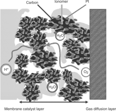
11.23 Catalyst layer microstructure and transport of gas, water, proton and electron in the electrode.
PTFE-bonded catalyst layer
In the early stages of DMFC, the components and fabrication methods almost followed that of PEMFC. PTFE, which was discovered in 1947, has high melt viscosity, high molecular weight (MW = 106), and high resistance to thermal degradation. These properties allow it to flow and penetrate through pores and form a good interfacial contact with the catalyst and carbon in the formation of PTFE-bonded catalyst layer, which is also called hydrophobic catalyst layer and can provide hydrophobic gas pores for reactants after heat treatment. It enlarges the gas/liquid interfacial area and facilitates gas diffusion in the catalyst layer, thus leading to better catalyst utilization and cell performance. But the catayst utilization in PTFE-bonded catalyst layer was not more than 20% due to high electrical reistance and proton resistance.151 Nafion solution is often impregnated into the PTFE-bonded catalyst layer to increase proton conduction. But Nafion solution could not penetrate deep into the electrode and uniformly distribute in the whole catalyst layer.
Nafion®-bonded catalyst layer
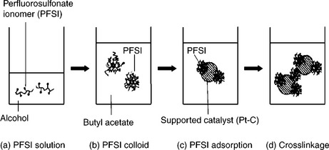
In 1993, Wilson et al.152 developed the Nafion-bonded catalyst layer in which the PTFE emulsion was replaced with Nafion ionomer. The binding material is the same polymer as the Nafion membrane. It was reported that Nafion-bonded catalyst layer had a power density of almost twice that of PTFE-bonded catalyst layer, which indicated that the catalyst utilization increased from 22% to 45%. The selection of dispersion media is vital to the structure and cell performance of Nafion-bonded catalyst layer. The primary role of dispersion media is to enable an intimate contact between catalyst and Nafion ionomer in order to create a three-phase interface (reactant, electrolyte and catalyst). The catalyst ink is a mixture of catalyst powder, solvent and ionomer, which changes into one of the three states: (i) solution; (ii) colloids and (iii) precipitates, depending on the interaction between the ionomer and the solvent. According to the cohesive energy density of Nafion,153 Nafion possesses two Hildeband solubility parameters (δ): 9.7 (cal/cm3)1/2 for the perfluorocarbon backbone (δ1) and 17.3 (cal/cm3)1/2 for the side chain (δ2). For example, the solubility parameters for n-propanol and water are 11.9 and 23.4 (cal/cm3)1/2, respectively. With dispersion media having high δ values (i.e., δ > δ1), Nafion ionomer can disperse well and form a solution. On the other hand, dispersion media with low δ values such as n-hexane (7.2 (cal/cm3)1/2) are not compatible with δ2 and consequently Nafion does not disperse, but forms precipitation.
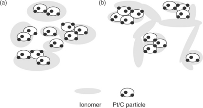
The influence of dispersion media on the catalyst layer structure and its correlation with fuel cell performance have been pioneered by Uchida et al.154 The effects of dispersion media on the dispersability of ionomer in the ink have been investigated. Nafion ionomer can be solubilized in organic solvents having a dielectric constant (ε) > 10, whereas colloidal solutions are obtained for solvents having a dielectric constant between 3 and 10 (Figs. 11.24 and 11.25). Precipitate forms in the solvents with ε < 3. Shin et al.155 reported that catalyst layers prepared via the colloidal method using n-butyl acetate (ε = 5) provided higher performing electrodes compared to those prepared by the solution method. It was suggested that the colloidal method yields a better continuity of the ionomer network and higher porosity of the catalyst layer. Kim et al.156 found that the catalyst layer prepared with less polar solvents, for example, dipropyl ketone (DPK, ε = 12.6) or n-butyl acetate (NBA, ε = 5), showed higher DMFC performance compared to the electrodes prepared with methanol (ε = 33) and IPA (ε = 18). The improvement was ascribed to an increase in the ionic conductivity of the catalyst layer and enlargement of the secondary pore structure that facilitate mass transfer.
Catalyst layers bonded with novel ionomers
In parallel to the development of new electrolyte membrane, a lot of efforts have also been devoted to novel ionomer to maximize the interfacial compatibility between the electrolyte membrane and catalyst layer.157,158 Hydrocarbon polymers exhibit better stability at elevated temperatures and better conductivity under low relative humidity (RH), with relatively lower cost compared to Nafion ionomer. Considering that sulfonated poly (ether ether ketone) (SPEEK) is known to be thermally stable and it exhibits lower methanol crossover than Nafion in DMFC, our group158 successfully introduced the SPEEK polymer as a binder in the catalyst layer while employing SPEEK as the membrane. The optimal IEC value and SPEEK ionomer content in the electrodes were found to be 1.33 meq.g−1 and 20 wt%, respectively. The MEAs with SPEEK ionomer exhibited better performance in DMFC than that with Nafion ionomer, which was attributed to a lower interfacial resistance, increased electrochemical active area of the catalyst layer, and lower methanol crossover.
11.6.2 Methods for catalyst layer fabrication
Conventional methods
To date, several techniques such as air spraying, painting, doctor blading, rolling and screen printing have been developed for fabrication of the catalyst layer. In early stages, due to the high viscosity of the catalyst ink made from PTFE emulsion and Pt/C powder, hand painting and brushing were the main techniques to apply the catalyst ink onto the carbon paper or carbon cloth. They are time saving processes, especially for highly concentrated ink and electrode with high metal loading. However, it is difficult to control the uniformity of the catalyst layer. The reproducibity and uniformity of the catalyst layer are much improved by air spraying (brushing), which requires a highly diluted and homogeneous catalyst ink. It is considered to be a potential process for mass production to meet the commercialization criteria. However, it is a time-consuming process for high-loading catalyst layers in DMFCs. Compared to hand painting and air spraying, screen printing is a fast and cost-effective process for the catalyst layer with high reproducibility.This techniqe usually requires viscous ink formation containing high boiling point solvent and high weight ratio of solid. Iteration steps of printing, drying, and weighing are required to achieve the targeted catalyst loading. Significant catalyst losses are unfortunately still unavoidable.
Inkjet printing
Inkjet printing (IJP) is a well-known drop-on-demand technology for depositing tiny droplets onto substrate without dependence on the high-speed operation of mechanical printing elements. Figure 11.26 gives a comparison of the hand painting process and the IJP method. Nozzle sizes for the printers are usually 20–30 μm with ink droplets as small as 1.5 pL. The printers can achieve high resolution (dots per inch) as well as the ability to print intricate features, gradients, and three-dimensional (3D) structures in a repeatable manner. Taylor et al.159 successfully introduced the inkjet printing to prepare the catalyst layer. As shown in Fig. 11.27, the specific shapes and areas can be precisely controlled with an enclosed structure, serpentine channels, and a block letter M. A variety of carbon-supported catalyst can be uniformly distributed on the surface of the carbon paper or electrolyte membrane with ultra-low loading (<0.05 mgPt/cm2).
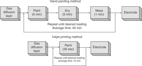
11.26 Time involved in inkjet printing method compared to that in hand painting. Source: Reprinted with permission from reference 159. Copyright Elsevier.
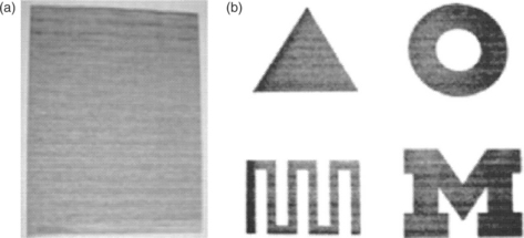
11.27 Illustration of successfully printed catalyst layers by the IJP method. (a) Illustration of successful printing of catalyst ink onto a carbon paper and (b) illustration of how catalyst ink can be controlled to specific shapes and areas with an enclosed structure, serpentine channels, and a block letter M. Source: Reprinted with permission from reference 159. Copyright Elsevier.
Dry production technique
A dry production technique was developed for ultrathin catalyst layers.160 This technique has several advantages such as high degree of automation, simplicity, freedom from organic solvent and elimination of time-consuming drying step. The main idea is to spray a dry catalyst layer directly onto the dry membrane to avoid waiting times for evaporating solvents. Figure 11.28 shows a scheme of the manufacturing process. The catalyst layer materials (e.g., Pt/C, PTFE powder, ionomer powder) were first mixed and homogenized in a knife mill, and then the mixed powder was atomized and sprayed through a slit nozzle directly onto a membrane in a nitrogen stream. The catalyst layer was further hot-pressed through a heat roller to improve the adhesion between the catalyst layer and membrane. The catalyst layer thickness can be as thin as 5 μm. Electrochemical investigation and single cell testing have shown that this technique has the capability to produce MEAs with excellent performances that are comparable with the commercial MEAs. It could be a potential industrial production technique for commercial MEAs.
Doctor blade technique
The doctor blade method developed by Bender et al.161 is an efficient way for realizing a high precision in catalyst loading with high reproducibility. They coated the catalyst onto a Teflon film and pointed out that doctor blade is significantly more precise and faster than the hand painting process. The doctor blade device was driven by the time base of a Scoltec X-Y plotter. The doctor blade is above the transfer substrate (PTFE film) and an appropriate amount of ink is micropipetted onto the substrate in front of the blade, and the time base drives the blade through the ink until the ink has covered a sufficient area. To overcome the issue of membrane swelling, our group162 developed an innovative process to apply the catalyst ink directly onto the membrane by a doctor blade technique. We used ethylene glycol (EG), diethylene glycol (DEG), triethylene glycol (TEG), tetraethylene glycol (TEEG) and glycerol as swelling agents. The membrane swelled to a greater extent, and the catalyst slurry was easily deposited on the preswollen membrane, which avoided the deformation of the catalyst layer and membrane.
In addition, some techniques have also been developed to apply the catalyst ink onto the gas diffusion layer or the electrolyte membrane, such as electrochemical deposition, electrophoretic deposition, vacuum sputtering, and ion-beam assisted deposition. Ultralow loading or ultrathin catalyst layer could be obtained with these methods for PEMFC, which greatly improved the catalyst utilization. They are all time-consuming processes for a high metal loading catalyst layer. Therefore, they are not suitable for mass production.
11.6.3 MEA structure
Ideal MEA structure
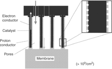
Middelman at NedStack fuel cell technology proposed an ideal electrode structure based on the optimum size of conductors and pores from computer modeling.163 Figure 11.29 shows a schematic image of such an ideal electrode structure. In this ideal electrode, platinum is finely dispersed on the electron conductor and the platinum particle size is around 2 nm. The catalyst-coated, oriented electron conductor is coated with a layer of proton-conducting polymer. The proton conductor is also oriented in a direction perpendicular to the membrane surface. The diameter of the catalyst-coated particles is 30 nm, the optimum diameter of the electron conductor is also 30 nm. The thickness of proton conducting polymer is approximately 10 nm. A thinner layer would increase proton resistance, but a thicker layer would be a diffusion barrier for the reactants.
Conventional structure
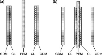
Primarily, there are two typical MEA structures for practical DMFC. One involves applying the catalyst ink onto the porous substrates (carbon paper or cloth) to make electrodes, then sandwiching an electrolyte membrane between the two electrodes and hot-pressing to form a MEA as displayed in Fig. 11.30a. Another involves applying the catalyst ink onto a Teflon substrate and transferring it to the electrolyte membrane by hot-pressing, or directly depositing the catalyst ink on both sides of the electrolyte membrane to produce a catalyst-coated membrane (CCM). The CCM is sandwiched by two porous gas diffusion media to form an MEA as illustrated in Fig. 11.30b.
Multi-catalyst layered MEA
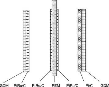
Wei et al.164 developed a multi-catalyst layered MEA for DMFC. Figure 11.31 displays the structure of the MEA consisting of five layers: the traditional PtRu/C layer and thin PtRu/C layer for the anode, the proton exchange membrane, and the traditional Pt/C layer and thin PtRu/C layer for the cathode. Three gradients were formed: catalyst concentration gradient, hydrophilicity gradient and porosity gradient, resulting in good mass transfer, good proton and electron conduction, and low methanol crossover. It was reported that the added thin PtRu/C layer improved the interfacial contact with the electrolyte membrane and avoided the delamination of catalyst layer. The thin PtRu/C layer in the cathode oxidized the methanol and reduced the harmful effect of the crossover of methanol on the cathode Pt/C catalyst. Therefore, the performance of a single cell consisting of multi-layer electrodes is dramatically improved.
Multi-membrane layered MEA
Our group165 designed multi-membrane layered MEA to reduce methanol crossover and improve cell performance. The multilayered membranes contained a thin layer of sulfonated poly (etheretherketone) (SPEEK) with different sulfonation levels and thickness, and two outer layers of recast Nafion. These multi-layered membranes showed a significant reduction in methanol crossover compared to the native Nafion membranes. This may be a promising strategy to overcome the difficulties of methanol crossover in DMFC.
11.6.4 MEA performance
DMFCs are viewed as a potential power source for various portable applications such as cellular phones, PDAs, laptop computers, military back power packs and auxiliary power units (APU) due to their high energy density, light weight, and simple system as well as their easy refueling and quick start-up. These significant advantages and huge market make the DMFC technology appealing. A lot of organizations and research groups are actively engaged in the development of high-performance single cells and stacks for portable device or vehicles applications.
The performance of DMFC single cell and stack are usually evaluated in term of maximum power density and current density at the specified working voltage. The operating conditions (methanol concentration, gas flow rate, cell temperature, back pressure), MEA components (catalyst type, catalyst loading, ionomer loading, thickness of membrane), electrode fabrication processes and polar plates are all factors influencing the performance of single cell and stack. It is very difficult to compare the MEA performances based on the reported data in the literature due to above factors. The MEA is usually tested in a single cell with an active area of 5–50 cm2. A diluted methanol solution in the concentration range of 0.5–5.0 M is pumped to the anode and pressurized oxygen or air is fed to the cathode. The effects of methanol concentrations on the cell performance have been investigated by several groups. High concentration of methanol could facilitate the mass transport and reduce concentration polarization at the anode, but it does not necessarily contribute to the high cell performance due to the problems of high methanol crossover at high concentrations of methanol feed. High concentration of methanol can cause a significant reduction in cathode potential. The OCP drops by 50–150 mV, which is closely related to the thickness of the electrolyte membrane and methanol concentration. For the cathode, high back pressure is often adopted to increase the oxygen concentration and facilitate oxygen diffusion in the catalyst layer. Meanwhile, it can impede methanol crossover from the anode to the cathode. High gas flow rate can also improve cell performance by reducing cathode flooding to some extent. In practice, a gas compressor or blower will be needed to maintain high gas pressure and high flow rate, which will consume 10-30% of power produced by DMFC stack.
Cell temperature is an important consideration in DMFC operation. Elevated temperature can increase the kinetics of methanol oxidation and overcome the CO species poisoning. Representative data for DMFC performance at high temperature are shown in Table 11.3. The highest power density of MEA reported by Aricö et al.,166 was around 450 and 290 mW/cm2 for single cells operated on oxygen and air, respectively, at the temperature of 130°C. These performances were achieved with 2 mg/cm2 Pt loadings on each electrode and 2 M methanol feed. Similar power density has also been achieved by Ren et al.161 at Los Alamos National Laboratory (LANL) based on MEA prepared with Nafion 112 membrane and 2.2 mg/cm2 Pt-RuOx catalyst and 2.3 mg/cm2 Pt black. The power outputs of this MEA are almost 400 mW/cm2 for the oxygen cathode at 130°C and about 250 mW/cm2 for the air cathode at 110°C.
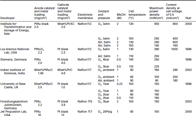
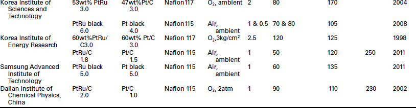
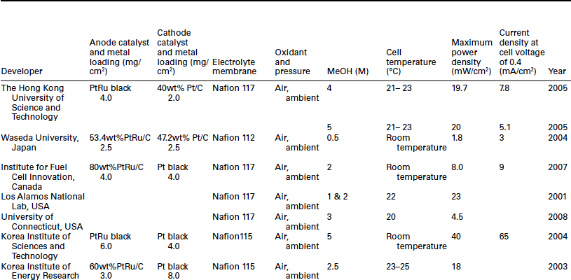
High performance of the DMFC is indispensable for portable applications at ambient temperature and pressure. The cell performance is much lower than that obtained at high cell temperature and pressurized conditions. Generally, the power density of DMFC varies between 10 and 40 mW/ cm2 under passive operation mode and ambient temperature as shown in Table 11.4. It is still too low for portable device and vehicle applications. Moreover, the high catalyst loading (> 2 mg/cm2) is not acceptable for large and even for small scale applications.
11.7 Conclusions and future trends
Improvements in DMFC performance has been realized over the years through the development of novel materials, optimization of electrode structure, and innovations in system integration. However, the methanol crossover, sluggish methanol oxidation and oxygen reduction kinetics, and the high cost of catalysts, membrane and bipolar plates remain to be an impediment to the commercialization of DMFC. This chapter provided an overview of the historical developments, materials development and MEA fabrication.
The activity of the MOR catalysts has been improved to some extent by tuning the composition, dispersion and support of the currently used PtRu materials. Similarly, the activity of the ORR catalysts has been improved by tuning the particle size, dispersion and support of the currently used Pt catalyst. Attempts to find catalysts more active than PtRu for MOR or Pt for ORR have also been ongoing for decades, but the PtRu and Pt systems still remain the best in terms of, respectively, the MOR and ORR activities. In this regard, development of high temperature (> 120°C) DMFCs or new catalysts that can overcome the poisoning effect of CO at the anode and methanol at the cathode can help.
Considerable efforts have been made to search for alternative membranes that can suppress methanol crossover. However, problems such as low proton conductivity and chemical instability have hampered this effort. Nevertheless, significant gains have been made in recent years, particularly by employing plain hydrocarbon membranes or blend hydrocarbon membranes based on acid–base interactions. Methanol crossover seems to be unavoidable as long as the proton conduction occurs by the vehicle mechanism. In this regard, development of new membranes that operate based on Grotthuss mechanism could help. Development of membranes with suppressed or little methanol crossover would also minimize or eliminate the poisoning of the cathode catalyst.
If catalysts are chosen with specific activity toward MOR or ORR, then a mixed-reactant DMFC can be designed, where methanol and oxygen can flow together through the cells and the anodic and cathodic reactions can take place on the respective electrodes due to the high selectivity of the catalysts. This approach can solve the problems of methanol crossover and methanol poisoning at the cathode.
In addition to the efforts in the development of more efficient, low-cost materials, novel processing and fabrication approaches for the electrode structure and MEA could offer significant gains. Finally, innovative system design and management could also offer additional gains.
11.8 Acknowledgements
This work was supported by the Office of Naval Research MURI grant No. N00014-07-1-0758 and Welch Foundation grant F-1254.
11.9 References
1. Schultz, T., Zhou, S., Sundmacher, K. Current status of and recent developments in the direct methanol fuel cell. Chemical Engineering & Technology. 2001; 24(12):1223–1233.
2. Scott, K., Taama, W.M., Argyropoulos, P. Material aspects of the liquid feed direct methanol fuel cell. Journal of Applied Electrochemistry. 1998; 28(12):1389–1397.
3. Lamy, C., Lima, A., LeRhun, V., Delime, F., Coutanceau, C., Leger, J.M. Recent advances in the development of direct alcohol fuel cells (DAFC). Journal of Power Sources. 2002; 105(2):283–296.
4. Carrette, L., Friedrich, K.A., Stimming, U. Fuel Cells – Fundamentals and Applications. Fuel Cells. 2001; 1(1):5–39.
5. Apanel, G., Johnson, E. Direct methanol fuel cells – ready to go commercial? Fuel Cells Bulletin. 2004; 2004(11):12–17.
6. Chen, E.L. Direct methanol fuel cell. In: Hoogers G., ed. Fuel Cell Technology Handbook. CRC Press, 2002.
7. Halpert, G., Surampudi, S. The JPL direct methanol liquid-fee polymer electrolyte membrane (PEM) fuel cell. Presented at International Conference on Fuel Cells, Long beach, California, 23–25 February 1994, 1994.
8. Hogarth, M.P., Ralph, T.R. Catalysis for low temperature fuel cells. Part III: Challenges for the direct methanol fuel cell. Platinum Metals Review. 2002; 46(4):146–164.
9. Zhou, S., Schultz, T., Peglow, M., Sundmacher, K. Analysis of the nonlinear dynamics of a direct methanol fuel cell. Physical Chemistry Chemical Physics. 2001; 3(3):347–355.
10. Lu, G.Q., Wang, C.Y. Electrochemical and flow characterization of a direct methanol fuel cell. Journal of Power Sources. 2004; 134(1):33–40.
11. DOE, U.S., 2010. http://www1.eere.energy.gov/hydrogenandfuelcells/mypp/ [Multi-year research, development and demonstration plan: Planned program activities for 2005–2015].
12. Ferrin, P., Nilekar, A.U., Greeley, J., Mavrikakis, M., Rossmeisl, J. Reactivity descriptors for direct methanol fuel cell anode catalysts. Surface Science. 2008; 602(21):3424–3431.
13. Park, K.W., Choi, J.H., Kwon, B.K., Lee, S.A., Sung, Y.E., Ha, H.Y., Hong, S.A., Kim, H., Wieckowski, A. Chemical and electronic effects of Ni in Pt/Ni and Pt/Ru/Ni alloy nanoparticles in methanol electrooxidation. The Journal of Physical Chemistry B. 2002; 106(8):1869–1877.
14. Lu, C., Rice, C., Masel, R.I., Babu, P.K., Waszczuk, P., Kim, H.S., Oldfield, E., Wieckowski, A. UHV, electrochemical NMR, and electrochemical studies of platinum/ruthenium fuel cell catalysts. The Journal of Physical Chemistry B. 2002; 106(37):9581–9589.
15. Strasser, P. Combinatorial optimization of ternary pt alloy catalysts for the electrooxidation of methanol. Journal of Combinatorial Chemistry. 2008; 10(2):216–224.
16. Markovic, N.M., Gasteiger, H.A., Ross, P.N., Jiang, X., Villegas, I., Weaver, M.J. Electro-oxidation mechanisms of methanol and formic acid on Pt-Ru alloy surfaces. Electrochimica Acta. 1995; 40(1):91–98.
17. Chen, Y.X., Miki, A., Ye, S., Sakai, H., Osawa, M. Formate, an active intermediate for direct oxidation of methanol on Pt electrode. Journal of the American Chemical Society. 2003; 125(13):3680–3681.
18. Choi, J.H., Park, K.W., Park, I.S., Nam, W.H., Sung, Y.E. Methanol electro-oxidation and direct methanol fuel cell using Pt/Rh and Pt/Ru/Rh alloy catalysts. Electrochimica Acta. 2004; 50(2–3):787–790.
19. Liu, Z., Kang, S., Shamsuzzoha, M., Nikles, D.E. Synthesis and characterization of PtRe alloy nanoparticles as electrocatalysts for methanol oxidation. J. Nanosci. Nanotech.. 2010; 10:4266–4272.
20. Zeng, J., Lee, J.Y. Effects of preparation conditions on performance of carbon-supported nanosize Pt-Co catalysts for methanol electro-oxidation under acidic conditions. Journal of Power Sources. 2005; 140(2):268–273.
21. Park, K.W., Choi, J.H., Kwon, B.K., Lee, S.A., Sung, Y.E., Ha, H.Y., Hong, S.A., Kim, H., Wieckowski, A. Chemical and electronic effects of Ni in Pt/Ni and Pt/Ru/Ni alloy nanoparticles in methanol electrooxidation. The Journal of Physical Chemistry B. 2002; 106(8):1869–1877.
22. Samjesk, G., Wang, H., Löffler, T., Baltruschat, H. CO and methanol oxidation at Pt-electrodes modified by Mo. Electrochimica Acta. 2002; 47(2223):3681–3692.
23. Frelink, T., Visscher, W., van Veen, J.A.R. On the role of Ru and Sn as promotors of methanol electro-oxidation over Pt. Surface Science. 1995; 335:353–360.
24. Liu, Z., Guo, B., Hong, L., Lim, T.H. Microwave heated polyol synthesis of carbon-supported PtSn nanoparticles for methanol electrooxidation. Electrochemistry Communications. 2006; 8(1):83–90.
25. Wang, K., Gasteiger, H.A., Markovic, N.M., Ross, P.N. On the reaction pathway for methanol and carbon monoxide electrooxidation on Pt-Sn alloy versus Pt-Ru alloy surfaces. Electrochimica Acta. 1996; 41(16):2587–2593.
26. Choi, J.H., Park, K.W., Park, I.S., Kim, K., Lee, J.S., Sung, Y.E. A PtAu nan-oparticle electrocatalyst for methanol electro-oxidation in direct methanol fuel cells. Journal of Electrochemical Society. 2006; 153(10):A1812–A1817.
27. Xu, D., Liu, Z., Yang, H., Liu, Q., Zhang, J., Fang, J., Zou, S., Sun, K. Solution-based evolution and enhanced methanol oxidation activity of monodisperse platinum copper nanocubes. Angewandte Chemie International Edition. 2009; 48(23):4217–4221.
28. Liu, H., Song, C., Zhang, L., Zhang, J., Wang, H., Wilkinson, D.P. A review of anode catalysis in the direct methanol fuel cell. Journal of Power Sources. 2006; 155(2):95–110.
29. Zhuang, L., Jin, J., Abruna, H.D. Direct observation of electrocatalytic synergy. Journal of the American Chemical Society. 2007; 129(36):11033–11035.
30. Aricö, A.S., Srinivasan, S., Antonucci, V. DMFCs: From fundamental aspects to technology development. Fuel Cells. 2001; 1(2):133–161.
31. Hamnett, A., Kennedy, B.J., Weeks, S.A. Base metal oxides as promotors for the electrochemical oxidation of methanol. Journal of Electroanalytical Chemistry. 1988; 240:349–353.
32. Fournier, J., Faubert, G., Tilquin, J.Y., Cote, R., Guay, D., Dodelet, J.P. Highperformance, low Pt content catalysts for the electroreduction of oxygen in polymer-electrolyte fuel cells. Journal of Electrochemical Society. 1997; 144(1):145–154.
33. Piela, P., Eickes, C., Brosha, E., Garzon, F., Zelenay, P. Ruthenium crossover in direct methanol fuel cell with Pt-Ru black anode. Journal of Electrochemical Society. 2004; 151(12):A2053–A2059.
34. Chen, W., Sun, G., Guo, J., Zhao, X., Yan, S., Tian, J., Tang, S., Zhou, Z., Xin, Q. Test on the degradation of direct methanol fuel cell. Electrochimica Acta. 2006; 51(12):2391–2399.
35. Gancs, L., Hult, B.N., Hakim, N., Mukerjee, S. The impact of Ru contamination of a Pt/C electrocatalyst on its oxygen-reducing activity. Electrochemical and Solid-State Letters. 2007; 10(9):B150–B154.
36. Rajesh, B., Karthik, V., Karthikeyan, S., Ravindranathan Thampi, K., Bonard, J.M., Viswanathan, B. Pt-WO3 supported on carbon nanotubes as possible anodes for direct methanol fuel cells. Fuel. 2002; 81(17):2177–2190.
37. Yuan, H., Guo, D., Qiu, X., Zhu, W., Chen, L. Influence of metal oxides on Pt catalysts for methanol electrooxidation using electrochemical impedance spectroscopy. Journal of Power Sources. 2009; 188(1):8–13.
38. Scibioh, M.A., Kim, S.K., Cho, E.A., Lim, T.H., Hong, S.A., Ha, H.Y. Pt-CeO2/C anode catalyst for direct methanol fuel cells. Applied Catalysis B: Environmental. 2008; 84(3–4):773–782.
39. Tang, Z., Lu, G. Synthesis and characterization of high performance Pt-(PrxCeyOz)/C catalysts for methanol electrooxidation. Applied Catalysis B: Environmental. 2008; 79(1):1–7.
40. Guo, D.J., Cui, S.K., Sun, H. Preparation of Pt-CeO2/MWNT nano-composites by reverse micellar method for methanol oxidation. Journal of Nanoparticle Research. 2009; 11(3):707–712.
41. Ye, F., Li, J., Wang, T., Liu, Y., Wei, H., Li, J., Wang, X. Electrocatalytic properties of platinum catalysts prepared by pulse electrodeposition method using SnO2 as an assisting reagent. The Journal of Physical Chemistry C. 2008; 112(33):12894–12898.
42. Serov, A., Kwak, C. Review of non-platinum anode catalysts for DMFC and PEMFC application. Applied Catalysis B: Environmental. 2009; 90(3–4):313–320.
43. Lee, E., Manthiram, A. One-step reverse microemulsion synthesis of Pt-CeO2/C catalysts with improved nanomorphology and their effect on methanol electrooxidation reaction. Journal of Physical Chemistry C. 2010; 114(49):21833–21839.
44. Chen, M., Wang, Z.-B., Ding, Y., Yin, G.-P. Investigation of the Pt-Ni-Pb/C ternary alloy catalysts for methanol electrooxidation. Electrochemistry Communications. 2008; 10(3):443–446.
45. Cooper, J.S., Jeon, M.K., McGinn, P.J. Combinatorial screening of ternary Pt-Ni-Cr catalysts for methanol electro-oxidation. Electrochemistry Communications. 2008; 10(3):1545–1547.
46. Jeon, M.K., Cooper, J.S., McGinn, P.J. Methanol electro-oxidation by a ternary Pt-Ru-Cu catalyst identified by a combinatorial approach. Journal of Power Sources. 2008; 185(2):913–916.
47. Ley, K.L., Liu, R., Pu, C., Fan, Q., Leyarovska, N., Segre, C., Smotkin, E.S. Methanol oxidation on single-phase Pt-Ru-Os ternary alloys. Journal of The Electrochemical Society. 1997; 144(5):1543–1548.
48. Lima, A., Coutanceau, C., Léger, J.M., Lamy, C. Investigation of ternary catalysts for methanol electrooxidation. Journal of Applied Electrochemistry. 2001; 31(4):379–386.
49. Wang, Z.-B., Zuo, P.-J., Yin, G.-P. Investigations of compositions and performance of PtRuMo/C ternary catalysts for methanol electrooxidation. Fuel Cells. 2009; 9(2):106–113.
50. Zhu, J., Cheng, F., Tao, Z., Chen, J. Electrocatalytic methanol oxidation of Pt0.5Ru0.5-xSnx/C (x = 0-0.5). The Journal of Physical Chemistry C. 2008; 112(16):6337–6345.
51. Chai, G.S., Yu, J.-S. Highly efficient Pt-Ru-Co-W quaternary anode catalysts for methanol electrooxidation discovered by combinatorial analysis. Journal of Materials Chemistry. 2009; 19(37):6842–6848.
52. Choi, W.C., Kim, J.D., Woo, S.I. Quaternary Pt-based electrocatalyst for methanol oxidation by combinatorial electrochemistry. Catalysis Today. 2002; 74(3–4):235–240.
53. Santhosh, P., Gopalan, A., Lee, K.P. Gold nanoparticles dispersed polyaniline grafted multiwall carbon nanotubes as newer electrocatalysts: Preparation and performances for methanol oxidation. Journal of Catalysis. 2006; 238(1):177–185.
54. Lu, X., Wang, H., Zhang, S., Cui, D., Wang, Q. Synthesis, characterization and electrocatalytic properties of carbon nitride nanotubes for methanol electrooxidation. Solid State Sciences. 2009; 11(2):428–432.
55. Liu, F., Wang, C.Y. Mixed potential in a direct methanol fuel cell. Journal of Electrochemical Society. 2007; 154(6):B514–B522.
56. Nørskov, J.K., Rossmeisl, J., Logadottir, A., Lindqvist, L., Kitchin, J.R., Bligaard, T., Jnsson, H. Origin of the overpotential for oxygen reduction at a fuel-cell cathode. The Journal of Physical Chemistry B. 2004; 108(46):17886–17892.
57. Xiong, L., Kannan, A.M., Manthiram, A. Pt-M (M = Fe, Co, Ni and Cu) electrocatalysts synthesized by an aqueous route for proton exchange membrane fuel cells. Electrochemistry Communications. 2002; 4(11):898–903.
58. Xiong, L., Manthiram, A. Influence of atomic ordering on the electrocatalytic activity of Pt-Co alloys in alkaline electrolyte and proton exchange membrane fuel cells. Journal of Materials Chemistry. 2004; 14(9):1454–1460.
59. Mukerjee, S., Srinivasan, S., Soriaga, M.P., McBreen, J. Effect of preparation conditions of Pt alloys on their electronic, structural, and electrocatalytic activities for oxygen reduction – XRD, XAS, and electrochemical studies. The Journal of Physical Chemistry. 1995; 99(13):4577–4589.
60. Jalan, V., Taylor, E.J. Importance of interatomic spacing in catalytic reduction of oxygen in phosphoric acid. Journal of Electrochemical Society. 1983; 130(11):2299–2302.
61. Markovi![]() , N.M., Schmidt, T.J., Stamenkovi
, N.M., Schmidt, T.J., Stamenkovi![]() , V., Ross, P.N. Oxygen reduction reaction on Pt and Pt bimetallic surfaces: A selective review. Fuel Cells. 2001; 1(2):105–116.
, V., Ross, P.N. Oxygen reduction reaction on Pt and Pt bimetallic surfaces: A selective review. Fuel Cells. 2001; 1(2):105–116.
62. Greeley, J., Nørskov, J.K., Mavrikakis, M. Electronic structure and catalysis on metal surfaces. Annual Review of Physical Chemistry. 2002; 53(1):319–348.
63. Xiong, L., Manthiram, A. Nanostructured Pt-M/C (M = Fe and Co) catalysts prepared by a microemulsion method for oxygen reduction in proton exchange membrane fuel cells. Electrochimica Acta. 2005; 50(11):2323–2329.
64. Stamenkovi![]() , V., Mun, B.S., Mayrhofer, K.J., Ross, P.N., Markovi
, V., Mun, B.S., Mayrhofer, K.J., Ross, P.N., Markovi![]() , N.M., Rossmeisl, J., Greeley, J., Nørskov, J.K. Changing the activity of electro–catalysts for oxygen reduction by tuning the surface electronic structure. Angewandte Chemie International Edition. 2006; 45(18):2897–2901.
, N.M., Rossmeisl, J., Greeley, J., Nørskov, J.K. Changing the activity of electro–catalysts for oxygen reduction by tuning the surface electronic structure. Angewandte Chemie International Edition. 2006; 45(18):2897–2901.
65. Stamenkovi![]() , V.R., Mun, B.S., Mayrhofer, K.J.J., Ross, P.N., Markovi
, V.R., Mun, B.S., Mayrhofer, K.J.J., Ross, P.N., Markovi![]() , N.M. Effect of surface composition on electronic structure, stability, and electrocatalytic properties of Pt-transition metal alloys: Pt-skin versus Pt-skeleton surfaces. Journal of the American Chemical Society. 2006; 128(27):8813–8819.
, N.M. Effect of surface composition on electronic structure, stability, and electrocatalytic properties of Pt-transition metal alloys: Pt-skin versus Pt-skeleton surfaces. Journal of the American Chemical Society. 2006; 128(27):8813–8819.
66. Stamenkovic, V.R., Fowler, B., Mun, B.S., Wang, G., Ross, P.N., Lucas, C.A., Markovic, N.M. Improved oxygen reduction activity on Pt3Ni(111) via increased surface site availability. Science. 2007; 315(5811):493–497.
67. Bonakdarpour, A., Wenzel, J., Stevens, D.A., Sheng, S., Monchesky, T.L., Lobel, R., Atanasoski, R.T., Schmoeckel, A.K., Vernstrom, G.D., Debe, M.K., Dahn, J.R. Studies of transition metal dissolution from combinatorially sputtered, nanostructured Pt1-xMx (M = Fe, Ni; 0<x<1) electrocatalysts for PEM fuel cells. Journal of Electrochemical Society. 2005; 152(1):A61–A72.
68. Toda, T., Igarashi, H., Uchida, H., Watanabe, M. Enhancement of the electroreduction of oxygen on Pt alloys with Fe, Ni, and Co. Journal of Electrochemical Society. 1999; 146(10):3750–3756.
69. Yeager, E. Dioxygen electrocatalysis: Mechanisms in relation to catalyst structure. Journal of Molecular Catalysis. 1986; 38(1–2):5–25.
70. Li, W., Lane, A.M. Investigation of Pt catalytic effects on carbon support corrosion of the cathode catalyst in PEM fuel cells using DEMS spectra. Electrochemistry Communications. 2009; 11(6):1187–1190.
71. Shao, M.H., Huang, T., Liu, P., Zhang, J., Sasaki, K., Vukmirovic, M.B., Adzic, R.R. Palladium monolayer and palladium alloy electrocatalysts for oxygen reduction. Langmuir. 2006; 22(25):10409–10415.
72. Ruban, A., Hammer, B., Stoltze, P., Skriver, H.L., Norskov, J.K. Surface electronic structure and reactivity of transition and noble metals. Journal of Molecular Catalysis A: Chemical. 1997; 115(3):421–429.
73. Kitchin, J.R., Norskov, J.K., Barteau, M.A., Chen, J.G. Role of strain and ligand effects in the modification of the electronic and chemical properties of bimetallic surfaces. Physical Review Letters. 2004; 93(15):156801. [4 pages].
74. Kitchin, J.R., Barteau, M.A., Chen, J.G., Norskov, J.K. Modification of the surface electronic and chemical properties of Pt(111) by subsurface 3d transition metals. Journal of Chemical Physics. 2004; 120(21):1737365. [7 pages].
75. Bligaard, T., Norskov, J.K. Ligand effects in heterogeneous catalysis and electrochemistry. Electrochimica Acta. 2007; 52(18):5512–5516.
76. Román-Martímez, M.C., Cazorla-Amorós, D., Linares-Solano, A., De Lecea, C.S.-M., Yamashita, H., Anpo, M. Metal-support interaction in Pt/C catalysts. Influence of the support surface chemistry and the metal precursor. Carbon. 1995; 33(1):3–13.
77. Joo, S.H., Choi, S.J., Oh, I., Kwak, J., Liu, Z., Terasaki, O., Ryoo, R. Ordered nanoporous arrays of carbon supporting high dispersions of platinum nanoparticles. Nature. 2001; 412(6843):169–172.
78. Raghuveer, V., Manthiram, A. Mesoporous carbon with larger pore diameter as an electrocatalyst support for methanol oxidation. Electrochemical and Solid-State Letters. 2004; 7(10):A336–A339.
79. Watanabe, M., Tsurumi, K., Mizukami, T., Nakamura, T., Stonehart, P. Activity and stability of ordered and disordered Co-Pt alloys for phosphoric acid fuel cells. Journal of Electrochemical Society. 1994; 141(10):2659–2668.
80. Mukerjee, S., Srinivasan, S., Soriaga, M.P., McBreen, J. Role of structural and electronic properties of Pt and Pt alloys on electrocatalysis of oxygen reduction. Journal of Electrochemical Society. 1995; 142(5):1409–1422.
81. Toda, T., Igarashi, H., Uchida, H., Watanabe, M. Enhancement of the electroreduction of oxygen on Pt alloys with Fe, Ni, and Co. Journal of Electrochemical Society. 1999; 146(10):3750–3756.
82. Xiong, L., Manthiram, A. Effect of atomic ordering on the catalytic activity of carbon supported PtM (M = Fe, Co, Ni, and Cu) alloys for oxygen reduction in PEMFCs. Journal of Electrochemical Society. 2005; 152(4):A697–A703.
83. Raghuveer, V., Manthiram, A., Bard, A.J. Pd-Co-Mo electrocatalyst for the oxygen reduction reaction in proton exchange membrane fuel cells. Journal of Physical Chemistry B. 2005; 109(48):22909–22912.
84. Fernandez, J.L., Raghuveer, V., Manthiram, A., Bard, A.J. Pd-Ti and Pd-Co-Au electrocatalysts as a replacement for platinum for oxygen reduction in proton exchange membrane fuel cells. Journal of the American Chemical Society. 2005; 127(38):13100–13101.
85. Raghuveer, V., Ferreira, P.J., Manthiram, A. Comparison of Pd-Co-Au electrocatalysts prepared by conventional borohydride and microemulsion methods for oxygen reduction in fuel cells. Electrochemistry Communications. 2006; 8(5):807–814.
86. Mustain, W.E., Kepler, K., Prakash, J. Investigations of carbon-supported CoPd3 catalysts as oxygen cathodes in PEM fuel cells. Electrochemistry Communications. 2006; 8(3):406–410.
87. Serov, A.A., Cho, S.Y., Han, S., Min, M., Chai, G., Nam, K.H., Kwak, C. Modification of palladium-based catalysts by chalcogenes for direct methanol fuel cells. Electrochemistry Communications. 2007; 9(8):2041–2044.
88. Serov, A.A., Min, M., Chai, G., Han, S., Kang, S., Kwak, C. Preparation, characterization, and high performance of RuSe/C for direct methanol fuel cells. Journal of Power Sources. 2008; 175(1):175–182.
89. Rivera-Noriega, R., Castillo-Hernández, N., Soto-Guzmán, A.B., Solorza-Feria, O. Oxygen reduction on RuxFey cluster electrocatalyst in acid electrolyte. International Journal of Hydrogen Energy. 2002; 27(4):457–460.
90. Ye, S., Vijh, A.K. Non-noble metal-carbonized aerogel composites as electrocatalysts for the oxygen reduction reaction. Electrochemistry Communications. 2003; 5(3):272–275.
91. Pattabiraman, R. Electrochemical investigations on carbon supported palladium catalysts. Applied Catalysis A: General. 1997; 153(1–2):9–20.
92. Savadogo, O., Lee, K., Oishi, K., Mitsushima, S., Kamiya, N., Ota, K.-I. New palladium alloys catalyst for the oxygen reduction reaction in an acid medium. Electrochemistry Communications. 2004; 6(2):105–109.
93. Zen, J.M., Manoharan, R., Goodenough, J.B. Oxygen reduction on Ru-oxide pyrochlores bonded to a proton-exchange membrane. Journal of Applied Electrochemistry. 1992; 22(2):140–150.
94. Zen, J.-M., Wang, C.-B. Oxygen reduction on ruthenium-oxide pyrochlore produced in a proton-exchange membrane. Journal of Electrochemical Society. 1994; 141(4):L51–L52.
95. McNicol, B.D., Rand, D.A.J., Williams, K.R. Direct methanol-air fuel cells for road transportation. Journal of Power Sources. 1999; 83(1–2):15–31.
96. Murthi, V.S., Urian, R.C., Mukerjee, S. Oxygen reduction kinetics in low and medium temperature acid environment: Correlation of water activation and surface properties in supported Pt and Pt alloy electrocatalysts. The Journal of Physical Chemistry B. 2004; 108(30):11011–11023.
97. Vante, N.A., Tributsch, H. Energy conversion catalysis using semiconducting transition metal cluster compounds. Nature. 1986; 323(6087):431–432.
98. Shukla, A.K., Raman, R.K. Methanol-resistant oxygen-reductuion catalysts for direct methanol fuel cells. Annual Review of Material Research. 2003; 33(1):155–168.
99. Jarvi, T.D., Sriramulu, S., Stuve, E.M. Potential dependence of the yield of carbon dioxide from electrocatalytic oxidation of methanol on platinum(100). The Journal of Physical Chemistry B. 1997; 101(19):3649–3652.
100. Ralph, T.R., Hogarth, M.P. Catalysis for low temperature fuel cells. Platinum Metals Review. 2002; 46(1):3–14.
101. Xiong, L., Kannan, A.M., Manthiram, A. Pt-M (M = Fe, Co, Ni and Cu) electrocatalysts synthesized by an aqueous route for proton exchange membrane fuel cells. Electrochemistry Communications. 2002; 4(11):898–903.
102. Mano, N., Fernandez, J.L., Kim, Y., Shin, W., Bard, A.J., Heller, A. Oxygen is electroreduced to water on a ‘wired’ enzyme electrode at a lesser overpotential than on platinum. Journal of the American Chemical Society. 2003; 125(50):15290–15291.
103. Sawai, K., Suzuki, N. Highly active nonplatinum catalyst for air cathodes. Journal of Electrochemical Society. 2004; 151(12):A2132–A2137.
104. Collman, J.P., Denisevich, P., Konai, Y., Marrocco, M., Koval, C., Anson, F.C. Electrode catalysis of the four-electron reduction of oxygen to water by dicobalt face-to-face porphyrins. Journal of the American Chemical Society. 1980; 102(19):6027–6036.
105. Gojkovic, S.L., Gupta, S., Savinell, R.F. Heat-treated iron (III) tetram-ethoxyphenyl porphyrin chloride supported on high-area carbon as an electrocatalyst for oxygen reduction: Part II. Kinetics of oxygen reduction. Journal of Electroanalytical Chemistry. 1999; 462(1):63–72.
106. Lefèvre, M., Dodelet, J.P., Bertrand, P. Molecular oxygen reduction in PEM fuel cells: Evidence for the simultaneous presence of two active sites in Fe-based catalysts. The Journal of Physical Chemistry B. 2002; 106(34):8705–8713.
107. Wagner, A.J., Wolfe, G.M., Fairbrother, D.H. Reactivity of vapor-deposited metal atoms with nitrogen-containing polymers and organic surfaces studied by in situ XPS. Applied Surface Science. 2003; 219(3–4):317–328.
108. Baranton, S., Coutanceau, C., Roux, C., Hahn, F., Léger, J.M. Oxygen reduction reaction in acid medium at iron phthalocyanine dispersed on high surface area carbon substrate: tolerance to methanol, stability and kinetics. Journal of Electroanalytical Chemistry. 2005; 577(2):223–234.
109. Matter, P.H., Zhang, L., Ozkan, U.S. The role of nanostructure in nitrogen-containing carbon catalysts for the oxygen reduction reaction. Journal of Catalysis. 2006; 239(1):83–96.
110. Vante, N.A., Jaegermann, W., Tributsch, H., Hoenle, W., Yvon, K. Electrocatalysis of oxygen reduction by chalcogenides containing mixed transition metal clusters. Journal of the American Chemical Society. 1987; 109(11):3251–3257.
111. Alonso-Vante, N., Tributsch, H., Solorza-Feria, O. Kinetics studies of oxygen reduction in acid medium on novel semiconducting transition metal chalcogenides. Electrochimica Acta. 1995; 40(5):567–576.
112. Bron, M., Bogdanoff, P., Fiechter, S., Dorbandt, I., Hilgendorff, M., Schulenburg, H., Tributsch, H. Influence of selenium on the catalytic properties of ruthenium-based cluster catalysts for oxygen reduction. Journal of Electroanalytical Chemistry. 2001; 500(1–2):510–517.
113. Zaikovskii, V.I., Nagabhushana, K.S., Kriventsov, V.V., Loponov, K.N., Cherepanova, S.V., Kvon, R.I., Bönnemann, H., Kochubey, D.I., Savinova, E.R. Synthesis and structural characterization of Se-modified carbon-supported Ru nanoparticles for the oxygen reduction reaction. The Journal of Physical Chemistry B. 2006; 110(13):6881–6890.
114. Shukla, A.K., Raman, R.K. Methanol-resistant oxygen-reduction catalysts for direct methanol fuel cells. Annual Review of Material Research. 2003; 33(1):155–168.
115. Ren, S.Z., Sun, G.Q., Li, C.N., Liang, Z.X., Wu, Z.M., Jin, W., Qin, X., Yang, X.F. Organic silica/Nafion (R) composite membrane for direct methanol fuel cells. Journal of Membrane Science. 2006; 282(1–2):450–455.
116. Antonucci, P.L., Arico, A.S., Creti, P., Ramunni, E., Antonucci, V. Investigation of a direct methanol fuel cell based on a composite Nafion (R)-silica electrolyte for high temperature operation. Solid State Ionics. 1999; 125(1–4):431–437.
117. Yen, C.Y., Lee, C.H., Lin, Y.F., Lin, H.L., Hsiao, Y.H., Liao, S.H., Chuang, C.Y., Ma, C.C.M. Sol–gel derived sulfonated-silica/Nafion (R) composite membrane for direct methanol fuel cell. Journal of Power Sources. 2007; 173(1):36–44.
118. Tricoli, V. Proton and methanol transport in poly(perfluorosulfonote) membranes containing Cs+ and H+ cations. Journal of the Electrochemical Society. 1998; 145(11):3798–3801.
119. Jiang, R.C., Zhang, Y., Swier, S., Wei, X.Z., Erkey, C., Kunz, H.R., Fenton, J.M. Preparation via supercritical fluid route of Pd-impregnated Nafion membranes which exhibit reduced methanol crossover for DMFC. Electrochemical and Solid State Letters. 2005; 8(11):A611–A615.
120. Jung, E.H., Jung, U.H., Yang, T.H., Peak, D.H., Jung, D.H., Kim, S.H. Methanol crossover through PtRu/Nafion composite membrane for a direct methanol fuel cell. International Journal of Hydrogen Energy. 2007; 32(7):903–907.
121. Liu, J., Wang, H.T., Cheng, S.A., Chan, K.Y. Nafion-polyfurfuryl alcohol nanocomposite membranes for direct methanol fuel cells. Journal of Membrane Science. 2005; 246(1):95–101.
122. Shao, Z.G., Hsing, I.M. Nafion membrane coated with sulfonated poly, vinyl alcohol-Nafion film for direct methanol fuel cells. Electrochemical and Solid State Letters. 2002; 5(9):A185–A187.
123. Easton, E.B., Langsdorf, B.L., Hughes, J.A., Sultan, J., Qi, Z.G., Kaufman, A., Pickup, P.G. Characteristics of polypyrrole/Nafion composite membranes in a direct methanol fuel cell. Journal of the Electrochemical Society. 2003; 150(10):C735–C739.
124. Li, L., Drillet, J.F., Macova, Z., Dittmeyer, R., Juttner, K. Poly(3,4-ethylenedioxythiophene)-modified Nafion membrane for direct methanol fuel cells. Russian Journal of Electrochemistry. 2006; 42(11):1193–1201.
125. Hobson, L.J., Ozu, H., Yamaguchi, M., Muramatsu, M., Hayase, S. Nafion(R)-117 modified by low dose EB irradiation: surface structure and physical properties. Journal of Materials Chemistry. 2002; 12(6):1650–1656.
126. Lin, H.L., Yu, T.L., Huang, L.N., Chen, L.C., Shen, K.S., Jung, G.B. Nafion/ PTFE composite membranes for direct methanol fuel cell applications. Journal of Power Sources. 2005; 150:11–19.
127. Chen, L.C., Yu, T.L., Lin, H.L., Yeh, S.H. Nafion/PTFE and zirconium phosphate modified Nafion/PTFE composite membranes for direct methanol fuel cells. Journal of Membrane Science. 2008; 307(1):10–20.
128. Woo, Y., Oh, S.Y., Kang, Y.S., Jung, B. Synthesis and characterization of sulfonated polyimide membranes for direct methanol fuel cell. Journal of Membrane Science. 2003; 220(1–2):31–45.
129. Ramya, K., Vishnupriya, B., Dhathathreyan, K.S. Methanol permeability studies on sulphonated polyphenylene oxide membrane for direct methanol fuel cell. Journal of New Materials for Electrochemical Systems. 2001; 4(2):115–120.
130. Fu, Y.Z., Manthiram, A. Synthesis and characterization of sulfonated polysulfone membranes for direct methanol fuel cells. Journal of Power Sources. 2006; 157(1):222–225.
131. Kerres, J.A. Development of ionomer membranes for fuel cells. Journal of Membrane Science. 2001; 185(1):3–27.
132. Yang, B., Manthiram, A. Sulfonated poly(ether ether ketone) membranes for direct methanol fuel cells. Electrochemical and Solid State Letters. 2003; 6(11):A229–A231.
133. Ghassemi, H., McGrath, J.E., Zawodzinski, T.A. Multiblock sulfonated-fluorinated poly(arylene ether)s for a proton exchange membrane fuel cell. Polymer. 2006; 47(11):4132–4139.
134. Liu, B., Kim, Y.S., Hu, W., Robertson, G.P., Pivovar, B.S., Guiver, M.D. Homopolymer-like sulfonated phenyl-and diphenyl-poly(arylene ether ketone) s for fuel cell applications. Journal of Power Sources. 2008; 185(2):899–903.
135. Kreuer, K.D. On the development of proton conducting polymer membranes for hydrogen and methanol fuel cells. Journal of Membrane Science. 2001; 185(1):29–39.
136. Oh, Y.S., Lee, H.J., Yoo, M., Kim, H.J., Han, J., Kim, T.H. Synthesis of novel crosslinked sulfonatod poly(ether sulfone)s using bisazide and their properties for fuel cell application. Journal of Membrane Science. 2008; 323(2):309–315.
137. Jeong, M.H., Lee, K.S., Lee, J.S. Cross-linking density effect of fluorinated aromatic polyethers on transport properties. Macromolecules. 2009; 42(5):1652–1658.
138. Di Vona, M.L., Sgreccia, E., Licoccia, S., Alberti, G., Tortet, L., Knauth, P. Analysis of temperature-promoted and solvent-assisted cross-linking in sulfonated poly(ether ether ketone) (SPEEK) proton-conducting membranes. Journal of Physical Chemistry B. 2009; 113(21):7505–7512.
139. Daniel, M.F., Desbat, B., Cruege, F., Trinquet, O., Lassegues, J.C. Solid-state protonic conductors – poly(ethylene imine) sulfates and phosphates. Solid State Ionics. 1988; 28:637–641.
140. Donoso, P., Gorecki, W., Berthier, C., Defendini, F., Poinsignon, C., Armand, M.B. Nmr, conductivity and neutron-scattering investigation of ionic dynamics in the anhydrous polymer protonic conductor peo(H3Po4)X. Solid State Ionics. 1988; 28:969–974.
141. Kreuer, K.D. On the complexity of proton conduction phenomena. Solid State Ionics. 2000; 136–137(4):149–160.
142. Wang, J.T., Wainright, J.S., Savinell, R.F., Litt, M. A direct methanol fuel cell using acid-doped polybenzimidazole as polymer electrolyte. Journal of Applied Electrochemistry. 1996; 26(7):751–756.
143. Ma, Y.L., Wainright, J.S., Litt, M.H., Savinell, R.F. Conductivity of PBI membranes for high-temperature polymer electrolyte fuel cells. Journal of the Electrochemical Society. 2004; 151(1):A8–A16.
144. Bouzek, K., Moravcova, S., Samec, Z., Schauer, J. H+ and Na+ ion transport properties of sulfonated poly(2,6-dimethyl-1,4-phenyleneoxide) membranes. Journal of the Electrochemical Society. 2003; 150(6):E329–E336.
145. Jorissen, L., Gogel, V., Kerres, J., Garche, J. New membranes for direct methanol fuel cells. Journal of Power Sources. 2002; 105(2):267–273.
146. Kerres, J.A. Development of ionomer membranes for fuel cells. Journal of Membrane Science. 2001; 185(1):3–27.
147. Fu, Y.Z., Manthiram, A., Guiver, M.D. Blend membranes based on sulfonated poly(ether ether ketone) and polysulfone bearing benzimidazole side groups for DMFCs. Electrochemical and Solid State Letters. 2007; 10(4):B70–B73.
148. Fu, Y.Z., Li, W., Manthiram, A. Sulfonated polysulfone with 1,3-1H-dibenzimidazole-benzene additive as a membrane for direct methanol fuel cells. Journal of Membrane Science. 2008; 310(1–2):262–267.
149. Li, W., Fu, Y.Z., Manthiram, A., Guiver, M.D. Blend membranes consisting of sulfonated poly(ether ether ketone) and polysulfone bearing 4-nitrobenzimidazole for direct methanol fuel cells. Journal of the Electrochemical Society. 2009; 156(2):B258–B263.
150. Li, W., Manthiram, A., Guiver, M.D. Acid–base blend membranes consisting of sulfonated poly(ether ether ketone) and 5-amino-benzotriazole tethered polysulfone for DMFC. Journal of Membrane Science. 2010; 362(1–2):289–297.
151. Cheng, X.L., Yi, B.L., Han, M., Zhang, J.X., Qiao, Y.G., Yu, J.R. Investigation of platinum utilization and morphology in catalyst layer of polymer electrolyte fuel cells. Journal of Power Sources. 1999; 79(1):75–81.
152. Wilson, M.S., Gottesfeld, S. Thin-film catalyst layers for polymer electrolyte fuel-cell electrodes. Journal of Applied Electrochemistry. 1992; 22(1):1–7.
153. Yeo, R.S. Dual cohesive energy densities of perfluorosulfonic acid (Nafion) membrane. Polymer. 1980; 21(4):432–435.
154. Uchida, M., Fukuoka, Y., Sugawara, Y., Ohara, H., Ohta, A. Improved preparation process of very-low-platinum-loading electrodes for polymer electrolyte fuel cells. Journal of the Electrochemical Society. 1998; 145(11):3708–3713.
155. Shin, S.J., Lee, J.K., Ha, H.Y., Hong, S.A., Chun, H.S., Oh, I.H. Effect of the catalytic ink preparation method on the performance of polymer electrolyte membrane fuel cells. Journal of Power Sources. 2002; 106(1–2):146–152.
156. Kim, J.H., Ha, H.Y., Oh, I.H., Hong, S.A., Lee, H.I. Influence of the solvent in anode catalyst ink on the performance of a direct methanol fuel cell. Journal of Power Sources. 2004; 135(1–2):29–35.
157. Li, Y.S., Zhao, T.S., Liang, Z.X. Effect of polymer binders in anode catalyst layer on performance of alkaline direct ethanol fuel cells. Journal of Power Sources. 2009; 190(2):223–229.
158. Lee, J.K., Li, W., Manthiram, A. Sulfonated poly(ether ether ketone) as an ionomer for direct methanol fuel cell electrodes. Journal of Power Sources. 2008; 180(1):56–62.
159. Taylor, A.D., Kim, E.Y., Humes, V.P., Kizuka, J., Thompson, L.T. Inkjet printing of carbon supported platinum 3-D catalyst layers for use in fuel cells. Journal of Power Sources. 2007; 171(1):101–106.
160. Gulzow, E., Schulze, M., Wagner, N., Kaz, T., Reissner, R., Steinhilber, G., Schneider, A. Dry layer preparation and characterisation of polymer electrolyte fuel cell components. Journal of Power Sources. 2000; 86(1–2):352–362.
161. Bender, G., Zawodzinski, T.A., Saab, A.P. Fabrication of high precision PEFC membrane electrode assemblies. Journal of Power Sources. 2003; 124(1):114–117.
162. Park, I.S., Li, W., Manthiram, A. Fabrication of catalyst-coated membrane-electrode assemblies by doctor blade method and their performance in fuel cells. Journal of Power Sources. 2010; 195(20):7078–7082.
163. Middelman, E. Improved PEM, fuel cell electrodes by controlled self-assembly. Fuel Cells Bulletin. 2002; 11:9–12.
164. Wei, Z.B., Wang, S.L., Yi, B.L., Liu, J.G., Chen, L.K., Zhou, W.J., Li, W.Z., Xin, Q. Influence of electrode structure on the performance of a direct methanol fuel cell. Journal of Power Sources. 2002; 106(1–2):364–369.
165. Li, W., Manthiram, A. Sulfonated poly(arylene ether sulfone) as a methanol-barrier layer in multilayer membranes for direct methanol fuel cells. Journal of Power Sources. 2010; 195(4):962–968.
166. Aricö, A.S., Creti, P., Baglio, V., Modica, E., Antonucci, V. Influence of flow field design on the performance of a direct methanol fuel cell. Journal of Power Sources. 2000; 91(2):202–209.
167. Ren, X.M., Wilson, M.S., Gottesfeld, S. High performance direct methanol polymer electrolyte fuel cells. Journal of the Electrochemical Society. 1996; 143(1):L12–L15.