
11
Introducing Business Connectivity Services
WHAT'S IN THIS CHAPTER?
Although Microsoft SharePoint Server 2010 is an excellent platform upon which to build information solutions, it will never be the only system in an organization. The simple fact is that organizations will always have additional systems, such as customer relationship management (CRM) and enterprise resource planning (ERP) — that target specific datasets and business processes. Additionally, organizations may have other custom applications, databases, and web services that are not part of the SharePoint infrastructure. These external systems (external to SharePoint that is) contain significant amounts of data and represent significant financial investments. As a consequence, these systems will not be replaced by any solution created solely in SharePoint.
The challenge, however, is that SharePoint solutions are often closely related to the data and processes contained in external systems. For example, a document library containing invoices may contain metadata also found in the ERP system or be addressed to a customer whose information is also in the CRM system. Without some way of utilizing data from the external systems, the SharePoint solution is forced to duplicate the same information. This duplication can then lead to data maintenance issues between the external system and the SharePoint solution.
In addition to the data challenges presented within SharePoint itself, there are challenges when integrating external data with Office 2010 documents. When salespeople create a quote, for example, they often look up customer contact information in a CRM system, copy it to the clipboard, and then paste it into the document. This duplication of effort obviously increases the time necessary to create documents. Furthermore, salespeople must be connected to the network in order to access the CRM system; they cannot easily create a quote while offline.
Failure to sufficiently integrate external systems with SharePoint solutions can slow the adoption of SharePoint within an organization. After all, the most important data used by information workers is often in external systems. Therefore, your solutions must consider how to integrate external data and that is where Business Connectivity Services (BCS) comes into play. This chapter is intended as an introduction to BCS technologies and is immediately followed by an advanced chapter on BCS development. Although these chapters provide significant technical information, readers interested in complete coverage should read the Wrox book Professional Business Connectivity Services(ISBN: 978-0-470-61790-8).
INTRODUCING BUSINESS CONNECTIVITY SERVICES
BCS is an umbrella term for a set of technologies that brings data from external systems into SharePoint Server 2010 and Office 2010. If you have worked previously with the Microsoft Office SharePoint Server 2007 Business Data Catalog, you might think of BCS as the evolution of the Business Data Catalog. If you have not previously worked with the Business Data Catalog, don't worry; no prior experience is required to understand or use BCS in SharePoint solutions. Figure 11-1 shows a diagram of the major functional blocks that make up BCS.
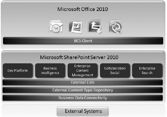
FIGURE 11-1
In the context of BCS, the term external system refers to any datasource that is outside of the SharePoint infrastructure. As previously noted, this can include third-party software, custom applications, databases, web services, and even cloud computing solutions. BCS communicates with external systems through the Business Data Connectivity (BDC) layer. The BDC layer contains the plumbing, runtime API, and connectivity functionality necessary to communicate with external systems.
Although the BDC layer provides connectivity to the external system, it does not dictate what data is returned from the system. The operations and schema for the returned data is instead defined by an External Content Type (ECT). An ECT contains an entity definition that specifies the exact fields that should be returned from an external source. For example, a “Customer” ECT might specify that the CustomerlD, FirstName, and LastName fields be returned from the CRM system. Additionally, an ECT defines the operations that can be performed. The available operations include create, read, update, delete, and query (CRUD). Defining ECTs is one of the primary activities involved in creating a BCS solution and may be performed in either Microsoft SharePoint Designer 2010 (SPD) or Microsoft Visual Studio 2010 (VS2010). When completed, ECTs are stored in the External Content Type Catalog.
Although it is possible to create many different custom solutions using BCS, the simplest way to expose external data in SharePoint is to use an external list. An external list is a SharePoint list that is based on an ECT. Just as standard lists (tasks, announcements, calendars, libraries, and so on) are based on content types, external lists are based on External Content Types. External lists behave similarly to standard lists, support views, and item editing. External lists can be used in support of any of the key functional areas within SharePoint Server.
In Office 2010, the BCS Client layer can use External Content Types to display external data in Office clients. This data may be displayed in Outlook using standard forms such as contact lists or utilized in Word to support metadata and document creation. In all cases, you can make use of InfoPath to enhance the presentation of external data. Finally, external lists may be taken offline with support from the SharePoint Workspace.
Creating Simple BCS Solutions
Although BCS solutions can be complex, they can also be created without code. Using the tools found in SPD and SharePoint, you can easily create an External Content Type and an external list. This data can then be edited in SharePoint or Office clients. This section walks through a simple BCS solution based on a SQL Server database. The database contains a single table of marketing campaign information, as shown in Figure 11-2. The goal of the walkthrough is to create a list in SharePoint and a calendar in Outlook based on this data.
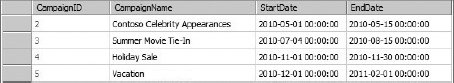
FIGURE 11-2
Creating External Content Types
The solution begins with the definition of External Content Types to define the schema and operations to perform on the data. Whether your BCS solution ultimately uses code or not, you will almost always define the ECTs using the SharePoint Designer. The tooling in SPD for creating ECTs was designed to be sophisticated enough to be used by professional developers across all types of BCS solutions. To begin, you simply open a development site in SPD and click the External Content Types object under the list of Site Objects, as shown in Figure 11-3.
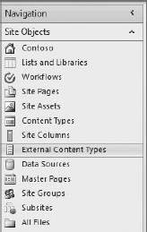
FIGURE 11-3
Clicking on New External Content Types allows you to start defining basic ECT information. The basic ECT information consists of a Name, Display Name, Namespace, and Version. You can also select from a list of various Office Types, which determines what form will be used to render the information when it is displayed in Outlook. Figure 11-4 shows the basic ECT information for the walkthrough with the Appointment Office Type selected.
Clicking on Operations Design View presents a form for defining connection information to an external system. Clicking the Add Connection button allows you to select from three types of connections: WCF, SQL, and .NET Type. Selecting WCF allows you to connect to a web service, SQL allows you to connect to a database, and .NET Type allows you to utilize a custom .NET Assembly Connector, which is covered later in this chapter. For this walkthrough, the SQL connection type was used, and the information shown in Figure 11-5 was specified.
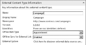
FIGURE 11-4
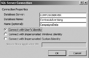
FIGURE 11-5
After the datasource connection is made, SPD can create operations for the ECT. When using a SQL connection, SPD can infer a significant amount of information about the datasource and the operations so it is easier to create the entire set of CRUD operations. In fact, all you have to do is right-click the table in the connection and select Create All Operations from the context menu, which launches a wizard to collect the small amount of information required to complete the operation definitions. Figure 11-6 shows the context menu in SPD.
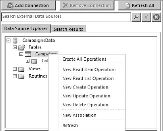
FIGURE 11-6
To complete the operation definitions, you must at least map fields from the ECT to fields in Outlook. This mapping determines how the ECT is displayed in the Outlook form. In this example, the Subject, Start, and End fields in Outlook must be mapped to the ECT. This is because Appointment was selected as the Office Type. For this walkthrough, CampaignName is mapped to Subject, StartDate to Start, and EndDate to End. When the wizard finishes, the ECT definition is complete; you can save it in SPD by clicking the Save button. The ECT is then visible in the list of ECTs for the site.
Creating External Lists
Once the ECT is created, you can use it as the basis for an external list. External lists can be created directly in SPD or in the browser using the Create menu in SharePoint. For this walkthrough, a new external list was created by selecting the Lists and Libraries object from the list of Site Objects and then clicking the New External List button. When you create a new external list, the set of available ECTS is presented. Figure 11-7 shows the list of available ECTs with the new Campaign type visible.
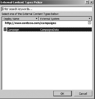
FIGURE 11-7
After the new external list is created, you can view it immediately in the browser. Because all of the CRUD operations were created, the list supports editing items, adding items, and deleting items. Figure 11-8 shows the new list in SharePoint Server 2010.
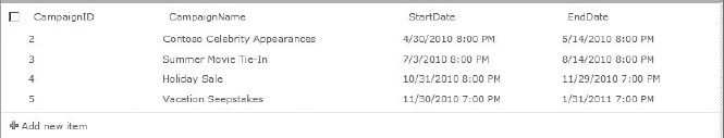
FIGURE 11-8
SharePoint Server 2010 supports taking lists offline through Microsoft Outlook. For this walkthrough, the external list was defined as an Appointment Office Type, and it can be synchronized with Outlook by clicking Connect to Outlook in the List tab of the Ribbon within SharePoint. When this button is clicked, a Visual Studio Tools for Office (VSTO) package is accessed and an installation screen is presented. This VSTO package must be installed for synchronization to continue. Figure 11-9 shows the installation screen presented to the user.
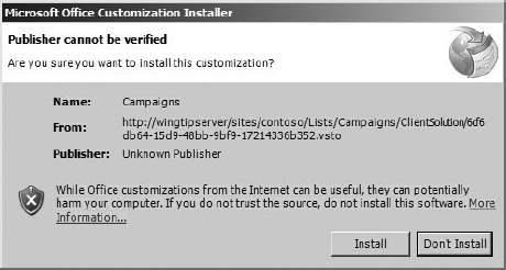
FIGURE 11-9
In addition to taking the list offline through Outlook, you can also take it offline through the SharePoint Workspace. In this case, you click the Sync to SharePoint Workspace button on the list tab in the SharePoint Ribbon. In a fashion similar to Outlook, a VSTO package installs, which makes the list available in the SharePoint Workspace. Figure 11-10 shows the list in the SharePoint Workspace.
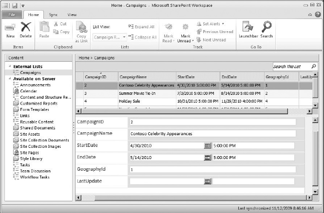
FIGURE 11-10
UNDERSTANDING BCS ARCHITECTURE
BCS is made up of several components and interacts with several services within SharePoint. To create effective BCS solutions, it is important to understand the architecture, components, and service interfaces available for development. A detailed diagram of this architecture is presented in Figure 11-11.
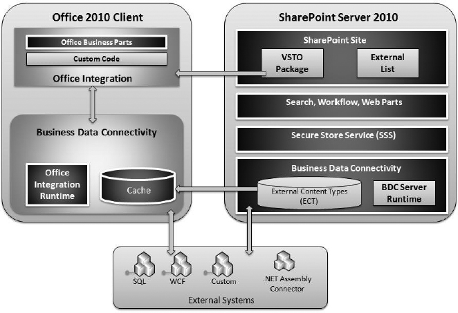
FIGURE 11-11
Understanding Connectors
As mentioned previously, BCS communicates with external systems using several connectors. The simple solution presented earlier utilized the SQL connector to access a SQL Server database, but BCS also supports a WCF connector for accessing web services. Together, the SQL and WCF connector cover a significant number of datasources, but they can't cover all possible scenarios.
In scenarios where you need more flexibility than is provided by the SQL and WCF connectors, you will likely build a .NET Assembly Connector instead. A .NET Assembly Connector is a project that you create in Visual Studio 2010 that contains the ECT definition and associated business logic for accessing a specific external system. The .NET Assembly Connector differs from the custom connector because it targets a specific instance of a system as opposed to all instances of a specific system type. In other words, you can use a .NET Assembly Connector to access a specific folder in Exchange while a custom connector could be used to access any folder in Exchange.
The .NET Assembly Connector is useful for aggregating data from multiple sources into a single ECT, which cannot be accomplished using a custom connector. While accessing an external system, the .NET Assembly Connector can also apply business rules to data before it is made available in SharePoint, and facilitating search indexing of a specific external system. The .NET Assembly Connector is covered in detail later in the chapter.
Understanding Business Data Connectivity
As stated previously, BDC is the term that encompasses the plumbing and runtime components of BCS. Both the server and the client have BDC components. These components are complementary so that you can use a similar approach to creating BCS solutions whether you are focused on the server, client, or both. On the server, the BDC components consist of the ECT catalog and the server-side BDC runtime. On the client, the BDC components consist of a metadata cache and the client-side BDC runtime.
Managing the Business Data Connectivity Service
When you create ECTs in SPD and save them, they are stored in the ECT catalog (also referred to as the metadata catalog). This catalog is a database that is accessed through the Business Data Connectivity service application. Figure 11-12 shows the basic architecture of the BDC service application.
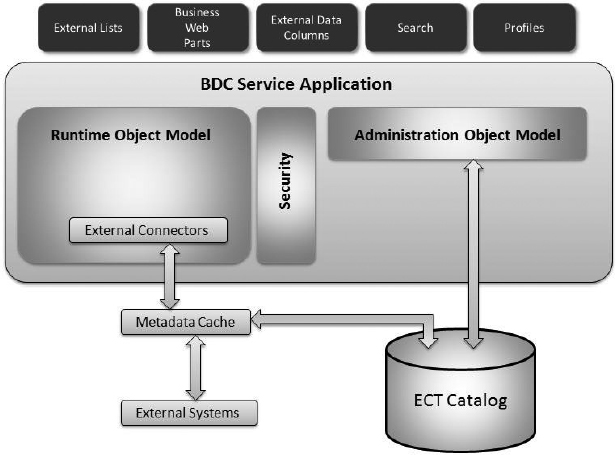
FIGURE 11-12
External connectors and ECT metadata are used to access the external systems and retrieve data through the runtime object model. The BDC service application then provides that data for use inside of SharePoint. A metadata cache is maintained in the service so that ECT data is easily accessed without having to be read from the database. This metadata cache is updated every minute to ensure that the latest ECT data is available to the farm.
Along with caching metadata to improve performance, BCS also can limit the total number of connections made to the external system. Additionally, the BDC service application also implements five throttle settings to limit the connections made and data returned from external systems. Table 11-1 lists the throttles and the default settings.
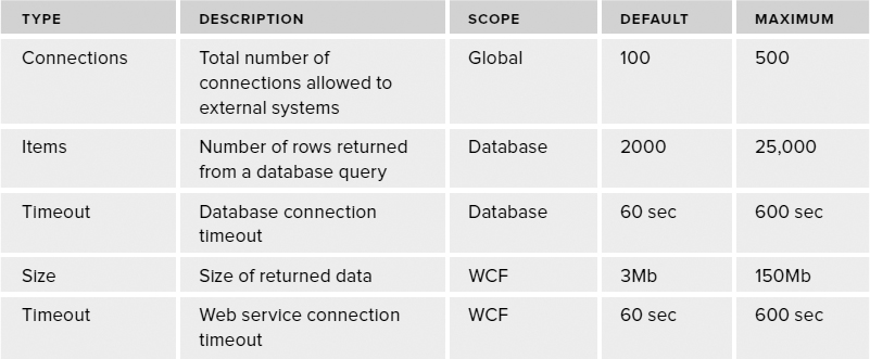
TABLE 11-1: BDC Service Application Throttles
Managing throttles is accomplished using PowerShell scripts. The following code displays the current throttle settings.
Add-PSSnapin Microsoft.SharePoint.PowerShell -ErrorAction SilentlyContinue
$bdc = Get-SPServiceApplicationProxy | Where {$_ -match “Business Data
Connectivity”}
Get-SPBusinessDataCatalogThrottleConfig -ThrottleType Connections -Scope Global You can modify each of the throttle settings using PowerShell. The following code shows how to change the number of items that can be returned from a database.
Add-PSSnapin Microsoft.SharePoint.PowerShell -ErrorAction SilentlyContinue
$bdc = Get-SPServiceApplicationProxy | Where {$_ -match “Business Data
Connectivity”}

$throttle = Get-SPBusinessDataCatalogThrottleConfig -ThrottleType Items -Scope
Database Alternately, you can simply disable any throttle. The following code shows how to disable the connections throttle.
Add-PSSnapin Microsoft.SharePoint.PowerShell -ErrorAction SilentlyContinue
$bdc = Get-SPServiceApplicationProxy | Where {$_ -match “Business Data
Connectivity”}
$throttle = Get-SPBusinessDataCatalogThrottleConfig -ThrottleType Connections The BDC service application is part of the service application framework in SharePoint. The management interface for the BDC service application is accessible through Central Administration by selecting Application Management ![]() Manage Service Applications. Figure 11-13 shows the BDC service application in Central Administration.
Manage Service Applications. Figure 11-13 shows the BDC service application in Central Administration.
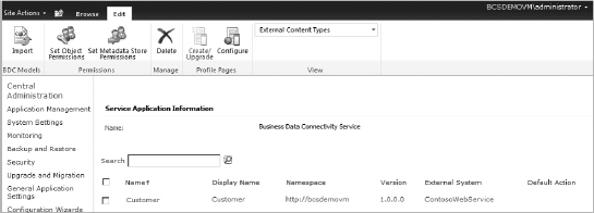
FIGURE 11-13
From the Service Applications page, you can click Properties in the Ribbon and see the basic service properties for the BDC service application. In the Properties dialog box, the name of the database where the ECTs are stored is displayed. This database is set up when the BDC service application is first created during farm installation and configuration. As with all services, you can also set administrative and connection permissions for the service so that it can be used by other servers in the SharePoint farm.
Clicking the Manage button on the Service Applications page opens the View External Content Types page. This page lists all ECTs that are currently stored in the catalog. Initially, the page is in Browse mode, but clicking the Edit tab in the Ribbon reveals administrative options for the ECTs. On the Edit tab, you can grant rights to manage the ECT catalog by clicking the Set Catalog Permissions button, and you can set rights for individual ECTs by clicking the Set Object Permissions button. This allows you to determine which users are able to use ECTs to access external systems.
On the Edit tab, there is also a drop-down list that determines how ECT information is presented on the page. Initially, the drop-down is set to External Content Types, which shows the ECTs in a list. Selecting External Data Sources from the drop-down list shows all the available connections that are defined. Selecting Application Models, on the other hand, lists the models that contain both connection and ECT information.
The list of application models is of special importance to the developer because the application model contains the reference to the ECT, the connection information for the external systems, security information, and more. Furthermore, the model can be exported using the drop-down menu on the list item and then subsequently imported into another catalog. When a model is exported, it is saved as an XML file known as a BDC metadata model. BDC metadata models can also be exported directly from SPD by right-clicking the ECT and selecting Export Application Model.
The following code shows part of a BDC metadata model based on the walkthrough earlier in the chapter. Developers who have previous experience with the MOSS Business Data Catalog will immediately recognize many of the elements in the listing. Take special note of the bolded code. In the LobSystemlnstance properties, you can see the basic connection information for the external system. These values were all set when the external system connection was specified in SPD.
<?xml version=“1.0” encoding=“utf-16” standalone=“yes”?>
<Model xmlns:xsi=“http://www.w3.org/2001/XMLSchema-instance”
xsi:schemaLocation=“http://schemas.microsoft.com/windows/2007/BusinessDataCatalog
BDCMetadata.xsd" Name=“SharePointDesigner-CampaignsData-Administrator-92aec13 8-31d3-
4155-980f-db4c681c22 60”
xmlns=“http://schemas.microsoft.com/windows/2007/BusinessDataCatalog”>
  <Properties>
    <Property Name=“Discovery” Type=“System.String”></Property>
  </Properties>
  <LobSystems>
    <LobSystem Type=“Database” Name=“SharePointDesigner-CampaignsData”>
      <Properties>
       <Property Name=“DiscoveryVersion” Type=“System.Int32”>0</Property>
       <Property Name=“WildcardCharacter” Type=“System.String”>%</Property>
       <Property Name=“Discovery” Type=“System.String”></Property>
      </Properties>
      <LobSystemInstances>
        <LobSystemInstance Name=“SharePointDesigner-CampaignsData”>
          <Properties>
           <Property Name=“DatabaseAccessProvider” Type=“System.String”>SqlServer</
Property>
           <Property Name=“RdbConnection Data Source” Type=“System.
String”>localhost</Property>
           <Property Name=“RdbConnection Initial Catalog”
                      Type=“System.String”>ContosoAdvertising</Property>
           <Property Name=“RdbConnection Integrated Security”
                    Type=“System.String”>SSPI</Property>
           <Property Name=“RdbConnection Pooling” Type=“System.Boolean”>true</
Property>
           <Property Name=“Discovery” Type=“System.String”></Property>
<Property Name=“ConnectionName” Type=“System.String”>CampaignsData</
Property>
     </Properties>
    </LobSystemInstance>
   </LobSystemInstances>
  </LobSystem>
 </LobSystems>
</Model>
The AuthenticationMode in the code sample is set to PassThrough. When set to this value, BCS will attempt to connect to the external system using the credentials of the current user. As you saw in the walkthrough, options also exist to provide an explicit set of credentials or to map credentials using the Secure Store Service (SSS), which is covered later in this chapter.
Introducing the BDC Server Runtime
The BDC Server Runtime consists of the runtime object model, the administration object model, and the security infrastructure. The runtime object model provides access to ECTs while the administration object model provides objects for managing the ECTs catalog. The security infrastructure facilitates authentication and authorization for ECT operations and external system access.
Understanding the Client Cache
When BCS solutions are taken to Office clients, a client cache is used to store external data for display with automatic synchronization between the client cache and the associated external system. The client cache is a SQL Server Compact Edition (SQLCE) database that is installed as part of the Office 2010 installation. The database is encrypted to prevent tampering, as there is no reason for developers to access the database directly.
A synchronization process (BCSSync.exe) runs on the client to synchronize the cache with the associated external systems. When CRUD operations are performed on data within the Office clients, the operations are queued inside the client cache and synchronized with the external system when it is available. The synchronization process will also attempt to update data in the cache at various intervals from the external system depending on the user settings and availability of the external system. Conflicts between the cache and the external system are flagged for the end user so that they can be resolved.
Introducing the Office Integration Runtime
The Office Integration Runtime (OIR) is the set of components and associated APIs that bind the ECTs to the Office clients and your own custom solutions. The OIR loads whenever a host Office client is started. The OIR is installed on the client as part of the Office 2010 installation process.
Understanding the Secure Store Service
The Secure Store Service (SSS) is a service application that provides for the storage, mapping, and retrieval of credential information. Typically, the credentials stored by SSS are used to access external systems that do not support Windows authentication. This is accomplished by mapping the stored credentials to an existing Windows user or group.
To store credential sets for an external system, a new target application must be created in SSS. The target application acts as a container for credential sets mapped to an external system. The target application settings page contains a name for the application and a setting to specify whether each individual user will have a separate set of mapped credentials or whether every user will map to a single common set of credentials. Figure 11-14 shows application settings mapping a single set of credentials to an Active Directory group.
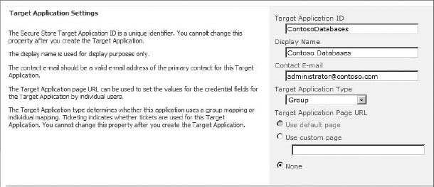
FIGURE 11-14
After the target application is defined, credential fields are defined. In most cases, the target application saves a username and password, but it is important to point out that SSS can save any text-based credential information. For example, a “domain” field could be added so that the credential sets consisted of username, password, and domain. Figure 11-15 shows typical username and password fields defined for an application.
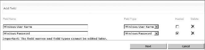
FIGURE 11-15
After the application and credential fields are defined, you must enter the actual credential information. For each user or group that will access the external system, a set of credentials must be created using the field definitions for the application. Figure 11-16 shows credentials being entered for an application. Once the credentials are in place, the application can be used during the definition of an ECT to allow access to the external system using the credentials stored in the SSS. If an end user should attempt to access the system without proper credentials in SSS, they will be directed to a login page so the credentials can be entered and stored.
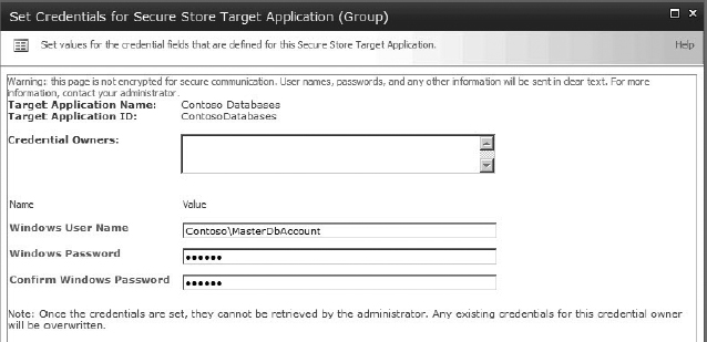
FIGURE 11-16
While BCS and SSS work well together to provide authentication in many scenarios, there may be times when you want to utilize SSS in custom solutions. In these cases, you can access SSS programmatically to retrieve credentials. These credentials can then be used by your solution (such as a web part) to access external systems directly without using BCS. The following code shows how to access the credentials in the default instance of SSS.
ISecureStoreProvider p = SecureStoreProviderFactory.Create();
string username = string.Empty;
string password = string.Empty;

using (SecureStoreCredentialCollection creds =
       p.GetCredentials(“ContosoDatabases”))
{
    foreach (SecureStoreCredential c in creds)
    {
        switch (c.CredentialType)
       {
            case SecureStoreCredentialType.UserName:
                username = c.Credential.ToString();
                break;

            case SecureStoreCredentialType.Password:
                password = c.Credential.ToString();
                break;

            case SecureStoreCredentialType.WindowsUserName:
                username = c.Credential.ToString();
                break;

            case SecureStoreCredentialType.WindowsPassword:
                password = c.Credential.ToString();
                break;

            case SecureStoreCredentialType.Generic:
                //Generic credentials
                break;

            case SecureStoreCredentialType.Key:
                //Key
                break;

            case SecureStoreCredentialType.Pin:
                //Pin
                break;
        }
    }

    //Log in using the credentials
}
Understanding Package Deployment
When an end user elects to synchronize an external list with Outlook or the SharePoint Workspace, BCS creates a VSTO click-once deployment package that contains all of the elements necessary to work with the list on the client. The package is created by BCS just in time and is stored under the list in a folder named ClientSolution. After the package is created, the deployment is started automatically.
The package contains the BCS model defining the external system, ECTs, operations, and security information necessary to access and modify data. The package also contains subscription information, which tells the client cache what data to manage and how it should be refreshed. Finally, the package contains pre- and post-deployment steps that you should take, such as creating custom forms in the client application to display the data.
Once deployed, the add-in can make use of Office business parts on the client to help render data. Office business parts are Windows form controls that display a single item or list of items in a task pane. These parts simplify the rendering process so that custom task panes do not have to be created for the client.
WORKING WITH BDC METADATA MODELS
The BDC Metadata Model is an XML file that completely defines the ECT, its connection to the external system, and its operations. When creating BCS solutions using the SPD tooling, you are simply building up the XML contained in the BDC Metadata Model. This model is then stored in the Metadata Store.
Although it is possible to create BCS solutions without looking at the XML contained in the BDC Metadata Model, professional solutions require a strong understanding of the elements in the model. When creating more advanced solutions in BCS, the BDC Metadata Model is often exported from SPD, modified, and imported when a desired feature is not directly supported by the SPD tooling. Furthermore, it is educational to export the BDC Metadata Model and examine it as changes are made.
You export a BDC Metadata Model from the list of External Content Types. After selecting an ECT, you can click the Export BDC Model button, which brings up the Export BDC Model dialog box. In this dialog box, you can select to export the Default model or the Client model. The Default model is the one used on the server and the Client model is the one stored in the client cache following list synchronization. The two models reflect any differences you made in the connection properties to be used on the server or client, but have the same ECT definitions. The models are exported with a BDCM extension, which is the file extension for all BDC Metadata Models. Figure 11-17 shows the Export BDC Model dialog box.
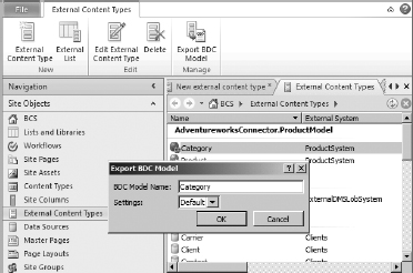
FIGURE 11-17
Once exported, the simplest way to work with the BDC Metadata Model is to change the file extension from .bdcm to .xml and open it in Visual Studio 2010. Although Visual Studio can open files with a .bdcm extension, doing so results in Visual Studio using its BCS designers instead of showing the XML directly. The BCS designers are intended for use with projects created solely in Visual Studio, which is covered in the next chapter.
The schema file for the BDC Metadata Model is named BDCMetadata.xsd and can be found in the /Program Files/Common Files/Microsoft Shared/web server extensions/14/Template/ XML directory. When working with exported models, you should copy the schema file into the directory where you exported the model. If you do this, you get IntelliSense support in Visual Studio when you open the file for editing.
You import a BDC Metadata Model through the BDC Service Application in Central Administration. When importing an edited model back into the BDC Service Application, you should be sure to update the ECT version, as a best practice. As an alternative, you can simply delete the existing model before importing the edited model.
Examining the BDC Metadata Model XML directly is an excellent way to learn the intricacies of the schema. Throughout this chapter, both the SPD tooling and resulting XML will be presented so that you can see exactly how the tools affect the model. As a starting point, the following code shows some of the basic elements used in the model.
<Model xmlns:xsi=“http://www.w3.org/2001/XMLSchema-instance”
       xsi:schemaLocation=”http://schemas.microsoft.com/…/BDCMetadata.xsd”
       xmlns=”http://schemas.microsoft.com/windows/2007/BusinessDataCatalog”
       Name=“My Model”>
   <LobSystems>
     <LobSystem>
       <LobSystemInstances>
         <LobSystemInstance/>
       </LobSystemInstances>
       <Entities>
         <Entity Name=“MyEntity”
                 DefaultDisplayName=“My Entity”
                 Namespace=“http://mynamespace”
                 Version=“1.0.0.0”
                 EstimatedInstanceCount=“10000”>
           <Methods>
           </Methods>
         </Entity>
       </Entities>
     </LobSystem>
   </LobSystems>
</Model>
The Model element is the root of the XML and contains the schema reference. This element also contains the Name attribute, which is displayed in the BDC Service Application. The LobSystem element is a container for the model associated with a particular external system. Notice that it is possible to have multiple external systems defined in the same model. The LobSystemInstance element provides connection information for a particular external system.
The Entity element begins the definition of an ECT for a particular external system. The Name attribute is the programmatic name of the ECT and the DefaultDisplayName attribute is the display name that will appear in the SharePoint UI. The Namespace attribute is used for disambiguation between ECTs that have the same programmatic name. The Version attribute is used to indicate the latest version of the ECT. All of these attributes are entered in SPD when creating a new ECT.
The EstimatedInstanceCount attribute is used as a hint to BCS solutions as to how many entity instances can be expected from the external system. The EstimatedInstanceCount attribute cannot be edited through SPD, and its use is determined solely by the application consuming the model. You could use this attribute, for example, when creating a custom web part to determine whether to load all of the data immediately or on demand. This is a good, albeit simple, example of why you might need to export a model, modify it by hand, and import it.
WORKING WITH EXTERNAL DATASOURCES
External datasources contain the data from external systems and are the starting point for any BCS solution. An ECT must be associated with an external datasource through one of four connector types: SQL Server, WCF Service, .NET Assembly, or Custom. When creating BCS solutions in SPD, you will primarily make use of the SQL Server or WCF Service connectors. The .NET Assembly and Custom connector types are typically part of a solution created in Visual Studio.
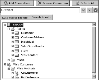
FIGURE 11-18
When creating a new ECT, you can associate a external datasource by clicking on the link entitled Click Here to Discover External Data Sources. Clicking the link takes you to the Operation Designer, where you can see all the available external datasources. This view allows additional external datasources to be added or existing ones to be removed. The Operation Designer also allows the structure of external datasources to be searched using a keyword. This facility helps locate tables, views, and web methods by name, which is helpful if there are many external datasources available. Figure 11-18 shows the Operation Designer with the results of a keyword search.
When working with an existing ECT, you can open the Operation Designer by clicking the Operations Design View button in the Ribbon. The Connection Properties dialog box can be opened by clicking the External System link in the ECT Information panel or by clicking the Edit Connection Properties button in the Ribbon. You can change the external datasource associated with an ECT by clicking the Switch Connected System button in the Ribbon. Figure 11-19 shows the available buttons in the Ribbon.
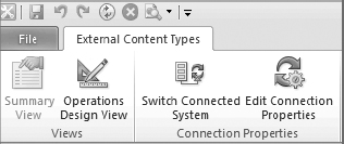
FIGURE 11-19
Connecting with the SQL Server Connector
The SQL Server Connector provides connections to Microsoft SQL Server, Oracle, OLE DB, and ODBC databases. Because databases represent the bulk of the available external data, the SQL Server Connector is used frequently in BCS solutions. The SharePoint Designer provides tooling to support connections with Microsoft SQL Server, but connections to Oracle, OLE DB, and ODBC sources require hand editing of the BDC Metadata Model.
Connecting to Microsoft SQL Server Databases
When adding a new SQL Server Connection in the Operation Designer, you must fill out the SQL Server Connection properties dialog box with the required information to connect to the external system. The following code shows the LobSystemInstance element for a typical connection to Microsoft SQL Server.
<LobSystems>
 <LobSystem Type=“Database” Name=“MySystem”>
  <Properties>
   <Property Name=“WildcardCharacter” Type=“System.String”>%</Property>
  </Properties>
  <LobSystemInstances>
  <LobSystemInstance Name=“MySystemInstance”>
   <Properties>
    <Property Name=“AuthenticationMode” Type=“System.String”>
      PassThrough
    </Property>
    <Property Name=“DatabaseAccessProvider” Type=“System.String”>
      SqlServer
    </Property>
    <Property Name=“RdbConnection Data Source” Type=“System.String”>
     AWSERVER
    </Property>
    <Property Name=“RdbConnection Initial Catalog” Type=“System.String”>
     Adventureworks
    </Property>
    <Property Name=“RdbConnection Integrated Security” Type=“System.String”>
     SSPI
    </Property>
    <Property Name=“RdbConnection Pooling” Type=“System.String”>
     True
    </Property>
   </Properties>
  </LobSystemInstance>
 </LobSystem>
</LobSystems>
For the SQL Server Connector, a series of Property elements are used to specify the values that define the connection to the database. The AuthenticationMode property determines how authentication is performed to the external system. The possible values for AuthenticationMode are listed in Table 11-2.
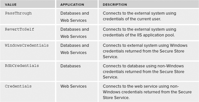
TABLE 11-2: Authentication Modes
The DatabaseAccessProvider property specifies what type of database is targeted. This value may be set to SqlServer, Oracle, OleDb, or Odbc. Depending upon the value selected for this property, other properties may be required as children of the LobSystemInstance element. In the case of the SqlServer example, the RdbConnection Data Source, RdbConnection Initial Catalog, RdbConnection Integrated Security, and RdbConnection Pooling properties are required. You'll recognize each of these properties as a component of a standard connection string.
Connecting to Oracle Databases
Because there is no tooling support in SPD for connecting to Oracle datasources, creating models for Oracle databases can be difficult. One approach is simply to start from scratch with a blank XML file and then import the model into the BDC Service Application. Another approach is to model the ECT against a SQL Server database, export the model, edit the model, and import the changed model. Neither approach is ideal. If you start from scratch, you are much more likely to commit typographical errors. On the other hand, modifying a SQL Server model is error-prone because the query syntax differs between SQL Server and Oracle. In any case, you must eventually end up with something that looks like the following code.
<LobSystems>
 <LobSystem Type=“Database” Name=“MySystem”>
  <Properties>
   <Property Name=“WildcardCharacter” Type=“System.String”>%</Property>
  </Properties>
  <LobSystemInstances>
   <LobSystemInstance Name=“MySystem Instance”>
    <Properties>
     <Property Name=“AuthenticationMode” Type=“System.String”>
      RdbCredentials
     </Property>
     <Property Name=“DatabaseAccessProvider” Type=“System.String”>
      Oracle
     </Property>
     <Property Name=“RdbConnection Data Source” Type=“System.String”>
      MY_NET_SERVICE_NAME
     </Property>
     <Property Name=“SsoApplicationId” Type=“System.String”>
      MY_SECURE_STORE_APP_ID
     </Property>
     <Property Name=“SsoProviderImplementation” Type=“System.String”>
      Microsoft.Office.SecureStoreService.Server.SecureStoreProvider,
      Microsoft.Office.SecureStoreService, Version=14.0.0.0,
      Culture=neutral, PublicKeyToken=71e9bce111e9429c
     </Property>
    </Properties>
   </LobSystemInstance>
  </LobSystemInstances>
 </LobSystem>
</LobSystems>
BCS META MAN
Because the tooling in SPD does not support all datasources and operations, a third-party market has emerged for tools that create BCS models. Our favorite third-party tool for creating BCS solutions is the BCS Meta Man. BCS Meta Man supports connections to Oracle and ODBC datasources along with other operations not supported by SPD. BCS Meta Man installs as an extension to Visual Studio 2010. Learn more at www.lightiningtools.com.
The AuthenticationMode property is set to RdbCredentials for connections to Oracle. This means that non-Windows credentials supplied by the Secure Store Service are used to access the Oracle database. The DatabaseAccessProvider property is set to Oracle to indicate that an Oracle is the target system. The RdbConnection Data Source property is set to the value of the Net Service Name, which is the alias for the database found in the tnsnames.ora file. The SsoApplicationId property is set to the name of the application in the Secure Store Service that is providing the credentials. Chapter 13 covers setting up the Secure Store Service in detail. The SsoProviderImplementation property refers to the implementation of the Secure Store Service. In the sample code, the property references the server-side Secure Store Service. If the model were used on the client, the following code should be substituted.
<Property Name=“SsoProviderImplementation” Type=“System.String”>
 Microsoft.Office.BusinessData.Infrastructure.
 SecureStore.LocalSecureStoreProvider,
 Microsoft.Office.BusinessData, Version=14.0.0.0, Culture=neutral,
 PublicKeyToken=71e9bce111e9429c
</Property>
Connecting to ODBC Datasources
Creating models for ODBC datasources is also not supported directly in SPD. Therefore, you must create the model from scratch and import it into the BDC Service Application. The following code shows what an ODBC connection looks like in the model XML.
<LobSystems>
 <LobSystem Name=“ODBC” Type=“Database”>
  <LobSystemInstances>
   <LobSystemInstance Name=“ODBCInstance”>
    <Properties>
     <Property Name=“AuthenticationMode” Type=“System.String”>
      PassThrough
    </Property>
     <Property Name=“DatabaseAccessProvider” Type=“System.String”>
      Odbc
     </Property>
     <Property Name=“RdbConnection Dsn” Type=“System.String”>
      MY_DSN_NAME
     </Property>
     <Property Name=“RdbConnection uid” Type=“System.String”>
      MY_USERNAME
     </Property>
     <Property Name=“RdbConnection pwd” Type=“System.String”>
      MY_PASSWORD
     </Property>
     <Property Name=“RdbConnection Trusted_Connection” Type=“System.String”>
      yes
     </Property>
     <Property Name=“RdbConnection integrated security” Type=“System.String”>
      true
     </Property>
    </Properties>
   </LobSystemInstance>
  </LobSystemInstances>
 </LobSystem>
</LobSystems>
The AuthenticationMode property is set to Passthrough, but note that the credentials used to access the datasource are provided in the RdbConnection uid and RdbConnection pwd properties. In fact, you can see how these properties build an ODBC connection string similar to the way it is done for Microsoft SQL Server.
Connecting to OLEDB Datasources
Just like Oracle and ODBC, creating models for OLEDB datasources is not supported by the SPD tooling. The BDC Metadata Model must be created from scratch and imported into the BDC Service Application. The following code shows what an OLEDB connection looks like for a Microsoft Access database.
<LobSystems>
 <LobSystem Type=“Database” Name=“MySystem” >
  <LobSystemInstances>
  <LobSystemInstance Name=“MySystemInstance” >
   <Properties>
    <Property Name=“AuthenticationMode” Type=“System.String” >
      PassThrough
    </Property>
    <Property Name=“DatabaseAccessProvider” Type=“System.String” >
      OleDb
    </Property>
    <Property Name=“RdbConnection Data Source” Type=“System.String” >
     C:Mydatabase.mdb
    </Property>
    <Property Name=“RdbConnection Persist Security Info”
    Type=“System.String” >
     false
    </Property>
    <Property Name=“RdbConnection Connection Provider” Type=“System.String” >
     Microsoft.ACE.OLEDB.12.0
    </Property>
   </Properties>
  </LobSystemInstance>
 </LobSystem>
</LobSystems>
The AuthenticationMode property is set to Passthrough. The RdbConnection Data Source refers to the location of the MS Access file. The RdbConnection Connection Provider specifies the OLEDB provider to use for the connection.
Connecting with the WCF Service Connector
The WCF Connector provides connections to web services including Windows Communication Foundation (WCF) and ASP.NET web services. The SharePoint Designer provides tooling for connecting with web services and their associated metadata so that operations can be defined against the services. The key to using a web service as an external datasource is for SPD to be able to access the metadata of the web service that describes the available operations. SPD supports accessing service metadata through both Web Service Description Language (WSDL) and metadata exchange.
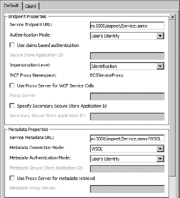
FIGURE 11-20
Connecting to ASP.NET Web Services
ASP.NET web services typically expose WSDL documents to describe the available operations. WSDL documents are accessed using the endpoint of the service appended with the query string ?WSDL. Figure 11-20 shows the Connection Properties dialog box with settings for an ASP.NET web service. Table 11-3 describes the settings in the dialog box.
TABLE 11-3: Web Service Connection Settings
| SETTING | DESCRIPTION |
| Service Endpoint URL | The base address of the web service |
| Authentication Mode | Used to select a value from Table 11-1. |
| Use Claims Based Authentication | Selected if the web service supports claims authentication. |
| Impersonation Level | Sets the Windows impersonation level as follows: None: No impersonation. Anonymous: The server cannot impersonate or identify the client. Identification: The server can identify the client, but cannot impersonate the client. Impersonation: The server can impersonate the client on the server onh Delegation: The server can impersonate the client locally and during requests to remote resources. |
| WCF Proxy Namespace | The programmatic namespace used for the generated proxy class. |
| Use Proxy Server for WCF Service Calls | Specifies a proxy server to use when calling the web service. |
| Secure Store Application ID | The name of the Secure Store Service application that will provide credentials for accessing the web service. See Chapter 13 for more details. |
| Specify Secondary Secure Store Application ID | A secondary Secure Store Service application that will supply additional credentials. These credentials are used when a web service expects credentials to be passed as parameters in the method call. See Chapter 13 for more details. |
| Service Metadata URL | The address of the metadata document. |
| Metadata Connection Mode | Specifies whether to obtain metadata as WSDL or through a MEX endpoint. |
| Metadata Authentication Mode | Used to select an authentication mode from the values in Table 11-1 that will be used when accessing service metadata. |
| Use Proxy Server for Metadata Retrieval | Specifies a proxy server to use when returning service metadata. |
| Specify Number of Connections | The maximum number of connections allowed to the service. |
The settings in the Connection Properties dialog box are used to generate the properties for the LobSystem and LobSystemInstance elements of the model. The exact properties presented in the model will vary according to the selections made in the dialog box. The following code shows how the settings in Figure 11-20 are translated into the BDC Metadata Model.
<LobSystems>
 <LobSystem Type=“Wcf” Name=“ASP.Net Web Service”>
  <Properties>
   <Property Name=“ReferenceKnownTypes” Type=“System.Boolean”>
    True
   </Property>
   <Property Name=“System.String”>
    Disco
   </Property>
   <Property Name=“WcfMexDocumentUrl” Type=“System.String”>
    http://webserver.aw.com:5000/aspnet/Service.asmx?WSDL
   </Property>
   <Property Name=“WcfProxyNamespace” Type=“System.String”>
    BCSServiceProxy
   </Property>
   <Property Name=“WildcardCharacter” Type=“System.String”>*</Property>
   <Property Name=“WsdlFetchAuthenticationMode” Type=“System.String”>
    PassThrough
   </Property>
  </Properties>
  <Proxy>EABvmrlbJFsHTQdvYZp1cdN6TVqQAAMA…AAAAAA</Proxy>
  <LobSystemInstances>
   <LobSystemInstance Name=“Item Service”>

    <Properties>
     <Property Name=“UseStsIdentityFederation” Type=“System.Boolean”>
      False
     </Property>
     <Property Name=“WcfAuthenticationMode” Type=“System.String”>
      PassThrough
     </Property>
     <Property Name=“WcfEndpointAddress” Type=“System.String”>
      http://webserver.aw.com:5000/aspnet/Service.asmx
     </Property>
     <Property Name=“WcfImpersonationLevel” Type=“System.String”>
      Identification
     </Property>
    </Properties>
   </LobSystemInstance>
  </LobSystemInstances>
 </LobSystem>
</LobSystems>
Along with the properties set in the model, you will also notice a Proxy element. This element has been significantly truncated in the code listing, but will normally contain a large text string. This large text string is the serialized proxy class that is generated by the SPD tooling when connecting to the web service. This proxy class is used by BCS to communicate with the web service when calling methods. Serializing the class in the BDC Metadata Model makes the class portable and simplifies deployment to client applications.
Connecting to WCF Web Services
WCF web services expose WSDL just like ASP.NET web services, but can also expose a metadata-exchanged (MEX) endpoint to describe the available operations. MEX endpoints can be used by SPD to support generating a proxy class against the service. Figure 11-21 shows the Connection Properties dialog box with settings for a WCF web service exposing a MEX endpoint.
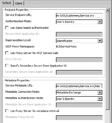
FIGURE 11-21
Just like ASP.NET web services, the values set in the Connection Properties dialog box are used to create the LobSystem and LobSystemInstance elements in the BDC Metadata Model. The properties in the model are the same as ASP.NET web services, but the values are set up to utilize a MEX endpoint instead of a WSDL endpoint. The following code shows a sample model connecting to a WCF web service.
<LobSystems>
 <LobSystem Type=“Wcf” Name=“Web Customers” >
  <Properties>
   <Property Name=“ReferenceKnownTypes” Type=“System.Boolean” >

    true
   </Property>
   <Property Name=“WcfMexDiscoMode” Type=“System.String” >
    WsMetadataExchange
   </Property>
   <Property Name=“WcfMexDocumentUrl” Type=“System.String” >
    http://webserver.aw.com:5000/customers/Service.svc/mex
   </Property>
   <Property Name=“WcfProxyNamespace” Type=“System.String” >
    BCSServiceProxy
   </Property>
   <Property Name=“WildcardCharacter” Type=“System.String” >*</Property>
   <Property Name=“WsdlFetchAuthenticationMode” Type=“System.String” >
    PassThrough
   </Property>
  </Properties>
  <Proxy>EABpFAAA…AAAAAAAAAAAA==</Proxy>
  <LobSystemInstances>
   <LobSystemInstance Name=“Web Customers” >
    <Properties>
     <Property Name=“UseStsIdentityFederation” Type=“System.Boolean” >
      False
     </Property>
      <Property Name=“WcfAuthenticationMode” Type=“System.String” >
       PassThrough
      </Property>
      <Property Name=“WcfEndpointAddress” Type=“System.String” >
       http://webserver.aw.com:5000/customers/Service.svc
      </Property>
      <Property Name=“WcfImpersonationLevel” Type=“System.String” >
       Identification
      </Property>
     </Properties>
    </LobSystemInstance>
   </LobSystemInstances>
 </LobSystem>
</LobSystems>
CREATING METHODS
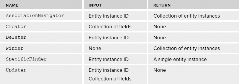
BCS method stereotypes define the operations that can be performed against an external system. The six method stereotypes supported by SPD are Finder, SpecificFinder, Creator, Updater, Deleter, and AssociationNavigator. These six method stereotypes are used to generate a view of many items, show details for a single item, create a new item, update an existing item, delete an item, and display data relationships, respectively.
Implementing Method Stereotypes
When implementing a method stereotype in the BDC Metadata Model, you use a Method and a MethodInstance element. The Method element defines the input parameters, output parameters, and filters that will be used with the method stereotype. The MethodInstance element defines the type of method stereotype to be implemented.
BDC Metadata Models typically consist of many Method elements defining operations against the external system. Each Method element can consist of one or more MethodInstance elements; however, it is typical to have a one-to-one relationship between Method and MethodInstance elements. This approach simplifies the model and makes it easier to develop the solution. The following code shows the basic XML schema to implement a method stereotype.
<Method Name=[Method Name]>
 <Properties>
  <Property>[Property Value]</Property>
 </Properties>
 <FilterDescriptors>
  <FilterDescriptor Type=[“Limit”, “PageNumber”, “Wildcard”, etc]
 </FilterDescriptor>
 <Parameters>
  <Parameter
   Direction=[“In”, “Out”, “InOut”, or “Return”]
   Name=[Parameter Name]
   AssociatedFilter=[Name of a FilterDescriptor]>
   <TypeDescriptor
    TypeName=[.NET Framework Type e.g, “System.Int32”] />
  </Parameter>
 </Parameters>
 <MethodInstances>
  <MethodInstance
   Type=[“Finder”, “SpecificFinder”, “Creator”, etc]
   Name=“MyMethodInstance”>
  </MethodInstance>
 </MethodInstances>
</Method>
Defining Properties
A Method element can contain one or more Property elements. These properties are specific to the method implementation and vary depending upon the connector type used to access the External System. Specific values are discussed in detail later in this chapter.
Defining Parameters
A Method element can contain one or more Parameter elements. Parameters are used as inputs and outputs to methods. Parameters are defined as In, Out, InOut, or Return types. The exact set of parameters required is based on the function signature of the method stereotype. For example, a Finder method might not have any In parameters and only a single Return parameter. A SpecificFinder method, on the other hand, might have a single In parameter representing the primary key of a record to return and a single Return parameter containing the record.
Parameter elements always contain one or more TypeDescriptor elements. TypeDescriptor elements are used to map data types in the external system to well known .NET Framework types that can be used by BCS. The types may be single-value types such as a System.String or can be collections of types. Collections of types are required, for example, when the return value from an external system is a record that contains multiple fields.
Defining Filters
A Method element can contain zero or more FilterDescriptor elements. Filters are used by BCS to provide system or user input to methods. For example, you can set a filter in a view definition for an external list as a way to specify which entity instances to return from an external system. You can also set filters by system, such as when a filter is used to limit return data based on the identity of the current user. Filters are always associated with an input parameter. This association is how the filter value is transmitted to or received from the method implementation. Table 11-4 lists the filters supported by SPD.
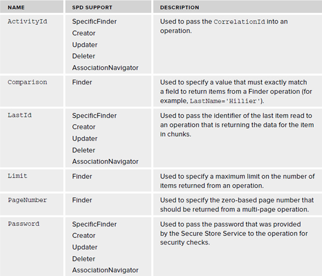
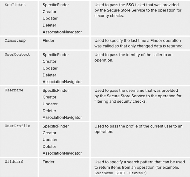
TABLE 11-4: BCS Filters
Understanding Stereotype Requirements
The value of the SPD tooling is that it knows how to create the correct set of properties, parameters, and filters for the supported method stereotypes. In cases where you are implementing method stereotypes by hand, however, you must be aware of the requirements implicit in each method stereotype. It is not enough to simply designate the Type attribute of a MethodInstance element; the parameters and filters must be defined so that an acceptable method signature results. Table 11-5 lists the parameters required for each method stereotype. Note that filters are generally not required, but can be applied as an option to further refine an operation.
TABLE 11-5: Required Parameters
Creating Methods for Databases
Databases are the easiest external datasources to work with in SPD. Because databases have tables, views, stored procedures, primary keys, and foreign keys, it is easier for the SPD tooling to create valid BDC Metadata Models with less human input. After an ECT is created and associated with a database as an external system, the Operation Designer shows the available tables, views, and stored procedures with which to work. You can use any of these objects as the starting point for a method.
Creating Finder Methods
Finder methods return views of the external system. You can use these views to create views in external lists, the Business Data web parts, or to support search. As such, an ECT can support multiple Finder methods. In order to start creating a Finder method, you can right-click one of the available tables, views, or stored procedures and select New Read List from the context menu. When you create a new Finder method, SPD starts the Read List Wizard.
The first step of the wizard asks for the name and display name of the Finder method. When naming methods, you should adopt a standard and use it consistently. The names that you select will appear in several places throughout SharePoint, so it's a good idea to use a naming standard that end users can read and understand.
The next step in the wizard allows you to set up filters for the Finder method. Note that when you create the first Finder method, SPD automatically marks it as the default Finder method. The default Finder method is the default view used for external lists and is the default method called by the crawler during search indexing. This is important because you do not want to filter the default Finder method in any way so this step in the wizard would be skipped.
When you create subsequent Finder methods, you will want to apply filters. Filters are important because they limit the amount of data that can be returned from the external system, thus making the solution more efficient. In the same way that you create views in a standard SharePoint list, you will want to create filtered Finder methods in SPD.
In the wizard, you can add a new filter to a Finder method by clicking the Add Filter Parameter button. Clicking this button, however, results only in the creation of an undefined filter, which generates a warning in the wizard. To configure the filter, you must click the Click to Add link, which opens the Filter Configuration dialog box. Figure 11-22 shows the sequence in the wizard.
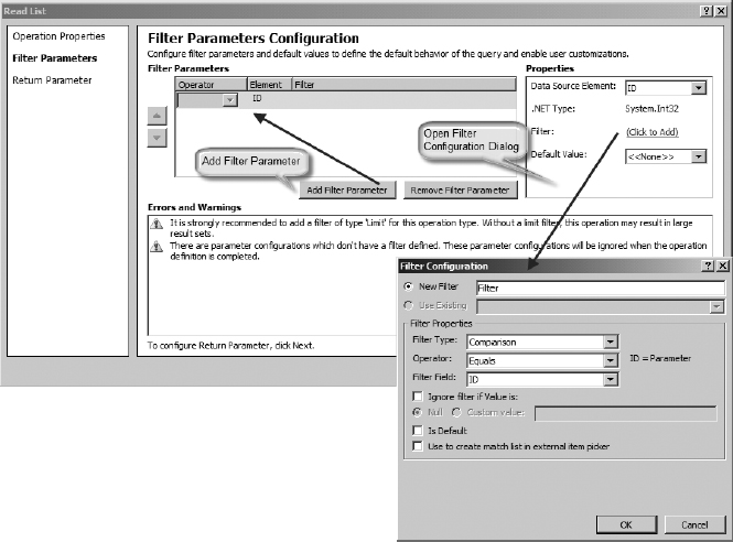
FIGURE 11-22
In the Filter Configuration dialog box, you can select the type of filter that you want and set properties such as values to ignore. After you complete the settings in the Filter Configuration dialog box, you can close it, but the filter definition is still not complete. In the Properties section of the wizard, you must select the field to be associated with the filter and provide a default value for the filter.
The next step in the wizard asks you to configure the values returned from the external system. Here you will be asked to specify the Identifier for the ECT. The Identifier field is the field that has the value that uniquely identifies an entity instance in the external system. For databases, this is most often simply the primary key. Simply select this field and check the Map to Identifier check box.
In this step, you also are prompted to specify fields to be displayed in the External Item Picker dialog box. This dialog is the picker control that appears in Microsoft Word whenever a library uses a field based on an ECT. This is important because the user sees only the fields that you mark, so they should be the fields the end user will need to search. Select each of the fields and click the Show in Picker check box.
In this step, it's also a good idea to take a close look at the display name for each field. Make sure that these values are readable because they appear as column headers in external lists. You can also uncheck any fields that you do not want to display in the view. Finally, if you have a DateTime field in the datasource that represents the last time the record was edited, mark that field as the Timestamp field. This allows Search to use the field in support of incremental crawls.
Modeling Finder Methods
Using tables, views, or stored procedures as sources results in the creation of different models. This is expected as the syntax to query these sources is different. The following code shows an implementation of the same Finder method using each of the three sources.
<!-- Table -->
<Method IsStatic=“false” Name=“AllNamesTable”>
 <Properties>
  <Property Name=“BackEndObject” Type=“System.String”>
   Names
  </Property>
  <Property Name=“BackEndObjectType” Type=“System.String”>
   SqlServerTable
  </Property>
  <Property Name=“RdbCommandText” Type=“System.String”>
   SELECT [ID], [Title], [FirstName], [MiddleName], [LastName],
   [EmailAddress], [Phone] FROM [MiniCRM].[Names]
  </Property>
  <Property Name=“RdbCommandType”
   Type=“System.Data.CommandType, System.Data, Version=2.0.0.0,
   Culture=neutral, PublicKeyToken=b77a5c561934e089”>
   Text
  </Property>
  <Property Name=“Schema” Type=“System.String”>
   MiniCRM
  </Property>
 </Properties>
 <Parameters>
  <Parameter Direction=“Return” Name=“AllNamesTable”>
   …
  </Parameter>
 </Parameters>
 <MethodInstances>
  <MethodInstance Type=“Finder” ReturnParameterName=“AllNamesTable”
   Name=“AllNamesTable” DefaultDisplayName=“All Names Table”>
  </MethodInstance>
  </MethodInstances>
 </Method>

<!-- View -->
<Method IsStatic=“false” Name=“AllNamesView”>
 <Properties>
  <Property Name=“BackEndObject” Type=“System.String”>
   vw_GetNames
  </Property>
  <Property Name=“BackEndObjectType” Type=“System.String”>

   SqlServerView
  </Property>
  <Property Name=“RdbCommandText” Type=“System.String”>
   SELECT [ID], [Title], [FirstName], [MiddleName], [LastName],
   [EmailAddress], [Phone] FROM [dbo].[vw_GetNames]
  </Property>
  <Property Name=“RdbCommandType”
   Type=“System.Data.CommandType, System.Data, Version=2.0.0.0,
   Culture=neutral, PublicKeyToken=b77a5c561934e089”>
   Text
  </Property>
  <Property Name=“Schema” Type=“System.String”>
   dbo
  </Property>
 </Properties>
 <Parameters>
  <Parameter Direction=“Return” Name=“AllNamesView”>
   …
  </Parameter>
 </Parameters>
 <MethodInstances>
  <MethodInstance Type=“Finder” ReturnParameterName=“AllNamesView”
   Name=“AllNamesView”DefaultDisplayName=“ All Names View”>
  </MethodInstance>
 </MethodInstances>
</Method>

<!-- Stored Procedure -->
<Method IsStatic=“false” Name=“AllNamesProcedure”>
 <Properties>
  <Property Name=“BackEndObject” Type=“System.String”>
   sp_GetNames
  </Property>
  <Property Name=“BackEndObjectType” Type=“System.String”>
   SqlServerRoutine
  </Property>
  <Property Name=“RdbCommandText” Type=“System.String”>
   [dbo].[sp_GetNames]
  </Property>
  <Property Name=“ RdbCommandType”
   Type=“System.Data.CommandType, System.Data, Version=2.0.0.0,
   Culture=neutral, PublicKeyToken=b77a5c561934e089”>
   StoredProcedure
  </Property>
  <Property Name=“Schema” Type=“System.String”>
   dbo
  </Property>
 </Properties>
 <Parameters>
  <Parameter Direction=“Return” Name=“AllNamesProcedure”>
   …
 </Parameter>
</Parameters>
  <MethodInstances>

  <MethodInstance Type=“Finder” ReturnParameterName=“AllNamesProcedure”
 Name=“AllNamesProcedure”DefaultDisplayName=“All Names Procedure”>
  </MethodInstance>
 </MethodInstances>
</Method>
Notice that the primary difference between each of the three implementations is the set of Property elements used in each. Tables and views, for example, use dynamic SQL statements, whereas the stored procedure uses a direct call to the procedure. Notice also that none of the methods has any input parameters or filters defined. If parameters were defined, however, a new stored procedure would have to be defined because any input parameters must be reflected in the stored procedure definition, whereas the dynamic SQL statements written against tables and views can simply be changed in the model.
When a stored procedure with input parameters is used, the wizard presents a screen that enables you to assign filters to the parameters. These filter values can then be set in the view definition of the external list by an end user or as an input parameter in the Business Data web parts. The following code shows a stored procedure that supports a wildcard as an input parameter.
<Method IsStatic=“false” Name=“NamesByWildcardProcedure”>
 <Properties>
  <Property Name=“BackEndObject” Type=“System.String”>
   sp_GetNamesWildcard
  </Property>
  <Property Name=“BackEndObjectType” Type=“System.String”>
   SqlServerRoutine
  </Property>
  <Property Name=“RdbCommandText” Type=“System.String”>
   [dbo].[sp_GetNamesWildcard]
  </Property>
  <Property Name=“RdbCommandType”
   Type=“System.Data.CommandType, System.Data, Version=2.0.0.0,
   Culture=neutral, PublicKeyToken=b77a5c5 61934e089”>
   StoredProcedure
  </Property>
  <Property Name=“Schema” Type=“System.String”>
   dbo
  </Property>
 </Properties>
 <FilterDescriptors>
  <FilterDescriptor Type=“Wildcard” FilterField=“LastName” Name=“Wildcard”>
   <Properties>
    <Property Name=“CaseSensitive” Type=“System.Boolean”>
     false
    </Property>
    <Property Name=“IsDefault” Type=“System.Boolean”>
     false
    </Property>
    <Property Name=“UsedForDisambiguation” Type=“System.Boolean”>
     false
    </Property>
   </Properties>

  </FilterDescriptor>
 </FilterDescriptors>
 <Parameters>
  <Parameter Direction=“In” Name=“@wildcard”>
   <TypeDescriptor TypeName=“System.String”
    AssociatedFilter=“Wildcard” Name=“@wildcard”>
   <Properties>
    <Property Name=“Order” Type=“System.Int32”>0</Property>
   </Properties>
   <DefaultValues>
    <DefaultValue
     MethodInstanceName=“NamesByWildcardProcedure” Type=“System.String”>
     A
   </DefaultValue>
   </DefaultValues>
  </TypeDescriptor>
 </Parameter>
 <Parameter Direction=“Return” Name=“NamesByWildcardProcedure”>
   …
 </Parameter>
 </Parameters>
 <MethodInstances>
  <MethodInstance Type=“Finder”
   ReturnParameterName=“NamesByWildcardProcedure”
   Name=“NamesByWildcardProcedure”
   DefaultDisplayName=“Names by Wildcard Procedure”>
  </MethodInstance>
 </MethodInstances>
</Method>
In the code, notice that a FilterDescriptor of type Wildcard has been added to the model. This filter is associated with the LastName field and the @wildcard input parameter. What this does is pass the value of the filter into the @wildcard input parameter. This means that the stored procedure must have a parameter by that exact name available, as shown in the following code.
CREATE PROCEDURE [dbo].[sp_GetNamesWildcard]
@wildcard nvarchar(10)
AS
SELECT ID,Title,FirstName,MiddleName,LastName,Suffix,EMailAddress,Phone
FROM MiniCRM.Names
WHERE LastName LIKE @wildcard + ‘%’
Remember that the purpose of filters is to retrieve input from either the end user or the system. In the case of the wildcard filter, the idea is to let the end user set up a view based on a partial string search of the last name. In the SharePoint interface, this appears as a value that can be set in the view definition of the external list.
Understanding the Default Finder
The default Finder method deserves special consideration in the design of any BCS solution. As stated previously, the first method Finder method created in SPD will be the default. When you create subsequent Finder methods, the wizard will present a check box that you can use to change the default Finder. If you do nothing, however, it will always be the first one created.
The default Finder method serves two important purposes. First, this is the method that will generate the default view for an external list. Second, this method will be used by the search indexer to retrieve records during the crawl process. The method is identified as the default Finder through the Default attribute of the MethodInstance element and the target of the crawl through the RootFinder property, as shown in the following code.
<MethodInstance
 Type=“Finder”
 ReturnParameterName=“AllNames”
 Default=“true”
 Name=“AllNames”
 DefaultDisplayName=“All Names”>
 <Properties>
  <Property Name=“RootFinder” Type=“System.String”></Property>
 </Properties>
</MethodInstance>
When SPD defines a Finder as both the default Finder and the root Finder, it can cause significant problems in your solutions. This is because the default Finder should be filtered, but the root Finder should not. Finder methods should generally have filters on them to limit the number of rows returned. If they do not have filters, BCS will throw an error if they return more than 2,000 rows to an external list. However, root Finders should never be filtered because the filtering will exclude items from the search index so that they will never appear in search results. Therefore, you must manually edit the BDC Metadata Model to assign the default Finder and root Finder to different Finder methods unless you know that your datasource will never exceed 2,000 rows, which is the limit for external lists.
Creating Other Methods
Creating SpecificFinder, Creator, Updater, and Deleter methods generally follows the same concepts as for Finder methods. The wizard walks you through the steps necessary to define appropriate parameters and filters. In the case of stored procedures, remember that any required input parameters or filters must be explicitly available as parameters in the stored procedure.
Creating Methods for Web Services
Web services are generally more difficult to work with than databases because the form of the exposed methods in a web service can vary widely. There is no explicit schema available for tables and views, and there are no primary/foreign keys available for inferring relationships. Therefore, the design of a BCS solution that utilizes web services must be carefully considered.
Although it is possible to utilize an existing web service as an external datasource, the requirements of the method stereotypes more often lead to the creation of a custom service for a BCS solution. Custom services should expose methods that correlate closely to BCS method stereotypes. The following code shows the programmatic interface for a simple WCF service.
[ServiceContract]
public interface IService
{

    [OperationContract]
    List<Customer> CrawlCustomers();

    [OperationContract]
    List<Customer> GetCustomers(int Limit);

    [OperationContract]
    List<Customer> GetCustomersByRegion(string Region);

    [OperationContract]
    Customer GetCustomer(string Id);

    [OperationContract]
    void CreateCustomer(string FirstName, string LastName);

    [OperationContract]
    void UpdateCustomer(string Id, string FirstName, string LastName);

    [OperationContract]
    void DeleteCustomer(string Id);

 }
 [DataContract]
 public class Customer
 {
     [DataMember]
     public string Id { get; set; }
     [DataMember]
     public string FirstName { get; set; }
     [DataMember]
     public string LastName { get; set; }
}
Notice how the exposed methods of the web service are designed in accordance with the requirements of Table 11-3. The Finder methods return collections of Customer entity instances, whereas the SpecificFinder returns only a single entity instance. The Creator, Updater, and Deleter methods return void.
Note also that there are three Finder methods exposed. The CrawlCustomers method has no filter and is intended for use by the indexer. The GetCustomers method accepts a limit filter to prevent causing errors in the external list if too many results are returned. The GetCustomerByRegion accepts a filter to limit the return results to customers in a given region. These parameters all appear in the SPD wizard so that they can be mapped to the appropriate filter types.
Defining Associations
Associations are relationships between ECTs. SPD supports one-to-many, self-referential, and reverse associations. One-to-many associations return many related entity instances from a single parent entity instance. Self-referential associations return entity instances of the same type as the parent entity instance. Reverse associations return a parent entity instance from a single child entity instance. Associations created in SPD are of type AssociationNavigator.
Creating One-to-Many Associations
The most common type of association in BCS solutions is the one-to-many association, whereby a parent entity instance is related to many child entity instances. This type of association supports scenarios such as when a single Customer has many Orders or when a single Client has many Contacts. This design is identical to the way database tables are related.
To create a one-to-many association, you must first define both External Content Types. The child ECT should be defined so that it contains a foreign key related to the parent ECT. This means that the Order ECT would contain a CustomerID field or the Contact ECT would contain a ClientID field. If the relationship is based on a database table or view, nothing else needs to be done. If the relationship is based on a stored procedure or web service method, you must also create a stored procedure or method that accepts the parent entity instance identifier and returns the child entity instances.
After you have the ECTs defined, the new association can be created from the Operation Designer. If the relationship will use tables or views, select the child table or view. If the relationship will use stored procedures or web services, select the procedure or method that will accept the parent entity instance identifier and return the child entity instances. Right-click and select New Association in the context menu to start the Association Wizard.
In the Association Wizard, you map the child ECT to the parent ECT by clicking the Browse button and selecting the parent ECT from a list. After you select the parent ECT, you must map the identifier of the parent ECT to the foreign key in the child ECT.
In the next screen of the wizard, you map the input parameter of the child to the foreign key. Most of the time this field has the same name as the identifier that was selected in the first screen, but they can be different.
<Method IsStatic=“false” Name=“ContactsForClient”> <Properties> <Property Name=“BackEndObject” Type=“System.String”> ClientContacts </Property> <Property Name=“BackEndObjectType” Type=“System.String”> SqlServerTable </Property> <Property Name=“RdbCommandText” Type=“System.String”> sp_GetAllClientContacts </Property> <Property Name=“RdbCommandType” Type=“System.Data.CommandType, System.Data, Version=2.0.0.0, Culture=neutral, PublicKeyToken=b77a5c5 61934e089”> StoredProcedure </Property> <Property Name=“Schema” Type=“System.String”>dbo</Property> </Properties> <Parameters> <Parameter Direction=“In” Name=“@ClientID”> <TypeDescriptor TypeName=“System.Int32” IdentifierName=“ClientID” IdentifierEntityName=“Client” IdentifierEntityNamespace=“http://clients_web” ForeignIdentifierAssociationName=“ContactsForClient” Name=“ClientID” /> </Parameter> <Parameter Direction=“Return” Name=“ContactsForClient”> … </Parameter> </Parameters> <MethodInstances> <Association Name=“ContactsForClient” Type=“AssociationNavigator” ReturnParameterName=“ContactsForClient” DefaultDisplayName=“Contacts For Client”> <Properties> <Property Name=“ForeignFieldMappings” Type=“System.String”> <?xml version=“1.0” encoding=“utf-16”?> <ForeignFieldMappings xmlns:xsi=“http://www.w3.org/2001/XMLSchema-instance” xmlns:xsd=“http://www.w3.org/2001/XMLSchema”> <ForeignFieldMappingsList> <ForeignFieldMapping ForeignIdentifierName=“ClientID” ForeignIdentifierEntityName=“Client” ForeignIdentifierEntityNamespace=“http://clients_web” FieldName=“ClientID” /> </ForeignFieldMappingsList> </ForeignFieldMappings> </Property> </Properties> <SourceEntity Namespace=“http://clients_web” Name=“Client” /> <DestinationEntity Namespace=“http://clients_web” Name=“Contact” /> </Association> </MethodInstances> </Method>
One-to-many relationships are used in the SharePoint interface to display entity instances. In an external list of child entity instances, the foreign key for the parent entity instance can be set using the picker, as shown in Figure 11-23. If a profile page is defined for the parent ECT, it will automatically be created to contain a list of related child ECTs.
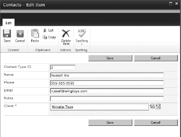
FIGURE 11-23
Creating Self-Referential Associations
Self-referential associations are created using the same approach as one-to-many relationships. The difference is that a self-referential relationship uses the same ECT as the parent and the child. Therefore, the ECT must have a separate field defined that acts like the foreign key in a one-to-many relationship, but instead refers to an entity instance of the same type.
As an example, consider creating an organizational chart from a single table of employees. The table contains an ID field as the primary key and a ManagerID field to relate the current record to another record in the table. Using this information, an association can be created between the Employee ECT ID and ManagerID field, as shown in the following code:
<Method IsStatic=“false” Name=“EmployeesForManager”>
<Properties>
<Property Name=“BackEndObject” Type=“System.String”>
Employees
</Property>
<Property Name=“BackEndObjectType” Type=“System.String”>
SqlServerTable
</Property>
<Property Name=“RdbCommandText” Type=“System.String”>
SELECT [ID], [ManagerID], [Title], [FirstName], [MiddleName],
[LastName], [EmailAddress], [Phone] FROM [dbo].[Employees]
WHERE [ManagerID] = @ID
</Property>
<Property Name=“RdbCommandType”
Type=“System.Data.CommandType, System.Data, Version=2.0.0.0,
Culture=neutral, PublicKeyToken=b77a5c5 61934e089”>
Text
</Property>
<Property Name=“Schema” Type=“System.String”>
dbo
</Property>
</Properties>
<Parameters>
<Parameter Direction=“In” Name=“@ID”>
<TypeDescriptor TypeName=“System.Int32” IdentifierName=“ID”
ForeignIdentifierAssociationName=“EmployeesForManager”
Name=“ManagerID” />
</Parameter>
<Parameter Direction=“Return” Name=“EmployeesForManager”>
…
</Parameter>
</Parameters>
<MethodInstances>
<Association Name=“EmployeesForManager” Type=“AssociationNavigator”
ReturnParameterName=“EmployeesForManager”
DefaultDisplayName=“Employees for Manager”>
<Properties>
<Property Name=“ForeignFieldMappings” Type=“System.String”>
<?xml version=“1.0” encoding=“utf-16”?>
<ForeignFieldMappings
xmlns:xsi=“http://www.w3.org/2001/XMLSchema-instance”
xmlns:xsd=“http://www.w3.org/2001/XMLSchema”>
<ForeignFieldMappingsList>
<ForeignFieldMapping ForeignIdentifierName=“ID”
ForeignIdentifierEntityName=“Employee”
ForeignIdentifierEntityNamespace=“http://bcs/orgchart”
FieldName=“ManagerID” />
</ForeignFieldMappingsList>
</ForeignFieldMappings></Property>
</Properties>
<SourceEntity Namespace=“http://bcs/orgchart” Name=“Employee” />
<DestinationEntity Namespace=“http://bcs/orgchart” Name=“Employee” />
</Association>
</MethodInstances>
</Method>
The key to creating the self-referential relationship is the SQL query that returns entity instances when the ManagerID=ID. Note that SPD does not always create this SQL query correctly when you are creating a new self-referential association in the tooling. Therefore, you should be sure to export and examine the query after the method is created. After it is created correctly, you can use the relationships like any other.
Creating Reverse Associations
Reverse associations return a single parent entity instance for a child entity instance. Reverse associations are not supported for tables and views, but are supported for stored procedures and web services because the reverse association in not inherent in the database schema. It must be explicitly programmed through a stored procedure or web service. For example, you could create a stored procedure that takes the identifier for a Contact and returns the parent Client entity instance, as shown in the following code.
CREATE PROCEDURE sp_GetClientByContactID
@ClientContactID int
AS
Select Clients.ClientID, Clients.Name, Clients.Address1, Clients.Address2,
Clients.City, Clients.Province, Clients.PostalCode, Clients.Country,
Clients.Phone, Clients.Fax, Clients.Web
From Clients
Inner Join ClientContacts
On Clients.ClientID = ClientContacts.ClientID
Where ClientContactID = SClientContactID
After the stored procedure is written, open the Operation Designer for the child ECT. Select the stored procedure, right-click, and select New Reverse Association from the context menu. As with the other associations, you can then browse and select the parent ECT.
WORKING WITH EXTERNAL LISTS
External lists support many of the same capabilities as standard SharePoint lists, such as custom list actions and custom forms. They do not, however, support all of the capabilities of standard lists, such as event handlers and workflows. This section takes a closer look at the capabilities of external lists and discusses how to work around their limitations.
Creating Custom List Actions
Custom list actions allow you to add a new button to the list item menu, view Ribbon, new form Ribbon, display form Ribbon, or the edit form Ribbon. The target of the button can be an existing form or an URL. For standard lists, you can also initiate a workflow from the button, but external lists do not support this function.
New custom list actions are created from SPD by selecting the list and clicking the Custom Action button in the Ribbon. This button will then open the Create Custom Action dialog box.
Creating Custom Forms
For every standard and external list, a set of forms is created to display, edit, and add items. Using the SharePoint Designer, you can create and customize these forms as ASPX pages or as InfoPath forms. This capability helps you enhance data presentation and perform field-level validation on items.
Creating ASPX Forms
When you create an external list, new, edit, and display forms are automatically created as appropriate, based on the operations defined for the associated ECT. Using SPD, you can see these forms by clicking on the Lists and Libraries object followed by the list of interest. The existing forms are listed on the summary page.
The default forms created for the external list utilize the List Form web part (LFWP). The LFWP executes Collaborative Application Markup Language (CAML) queries against the external list to display items. Unfortunately, the LFWP does not support modifying its presentation; a new form must be created instead.
Clicking the New button above the form list in the summary page opens the Create New List Form dialog box. This dialog box is used to create new, edit, and display forms that are based on the Data Form web part (DFWP). The DFWP utilizes XSLT to transform list data into a display. Modifying this XSLT can easily change the presentation of list data.
As an example, consider an external list that returns information about SharePoint images. The BCS solution has a column called Path that returns the path to the image. In a simple BCS solution, Path appears as a column and the user simply sees the text of the URL. A better experience, however, would be to show the image itself. This can be done by adding a new display form and modifying the XSLT, as shown in the following code.
<img>
 <xsl:attribute name=“src”>
  <xsl:value-of select=“@Path”/>
 </xsl:attribute>
</img>
In addition to using SPD, you can also modify the list forms inside of the SharePoint 2010 interface. While viewing the external list, click on the List tab in the Ribbon. The Modify Form Web Parts button enables you to select a form to modify. The difference is that you will be modifying the web part that is rendering the list using the Properties pane.
Creating InfoPath Forms
Instead of ASPX pages, you can choose to create custom InfoPath forms for the external list. InfoPath form creation can be initiated directly from SPD by clicking the Design Forms in InfoPath button from the List Summary page. This action opens InfoPath with a default form that you can edit.
InfoPath forms are easier to create, and offer simpler styling and advanced controls. Using InfoPath, you can take advantage of lists and drop-downs as well as styles and themes. When the form is complete, you must save it and then execute a Quick Publish. Quick publishing is available by clicking the File tab in InfoPath. Once published, the form is available on the new, edit, and display forms.
SUMMARY
Business Connectivity Services (BCS) provides the infrastructure and tooling necessary to bring external data into SharePoint. When creating BCS solutions for SharePoint 2010, consider the SharePoint Designer should be considered as your primary tool. The tooling support in SPD is easier to use than the equivalent tooling in Visual Studio. Additionally, you can export the model and edit it by hand to include capabilities not supported in the SPD tooling. In short, you should be able to use SPD for the majority of your solutions that are based on databases and web services.