
Chapter 12: Twisted and Chiral Nematicons
Warsaw University of Technology, Warsaw, Poland
12.1 Introduction
The uniqueness of nematicons is connected with the reorientational nonlinearity, by which light can change the initial orientation of liquid crystals. Such orientation, being the result of long-range interactions between molecules, is introduced at the boundaries and can be modified by electric or magnetic fields [1–3]. Solitary waves in nematic liquid crystals (NLCs) were investigated in capillaries [4–6], but the most often used configurations are planar cells with two parallel glass plates. In such cells, NLC can be homogeneously oriented, for example, in the homeotropic texture (where molecules are perpendicular to the glass plates) [7–9] or in the homogenic (planar) texture (where molecules are parallel to the glass plates) [10, 11]. Configurations in which the mean direction of the molecules (molecular director ![]() ) varies across the cell thickness, as in planar cells biased by a low-frequency external electric field [12–14], seem to be promising. A nonhomogeneous initial orientation can also be introduced by the boundary conditions, as in hybridly aligned nematics (molecules parallel to one plate and perpendicular to the second plate) or in twisted nematic liquid crystals (TNLC, in which the molecules are parallel to both plates but twisted within the layer thickness). This twisted orientation also characterizes chiral nematic liquid crystals (ChNLC, cholesteric liquid crystals).
) varies across the cell thickness, as in planar cells biased by a low-frequency external electric field [12–14], seem to be promising. A nonhomogeneous initial orientation can also be introduced by the boundary conditions, as in hybridly aligned nematics (molecules parallel to one plate and perpendicular to the second plate) or in twisted nematic liquid crystals (TNLC, in which the molecules are parallel to both plates but twisted within the layer thickness). This twisted orientation also characterizes chiral nematic liquid crystals (ChNLC, cholesteric liquid crystals).
Nematicons in TNLC and ChNLC have properties similar to standard nematicons in other configurations (Chapter 1): they are observed over distances of a few millimeters, they exist in a wide range of optical powers above a few milliWatts, they can be redirected by external electric fields, their excitation depends on light polarization, they can guide other signals, and their mutual interactions are attractive. However, at variance with other orientations, a cell filled by ChNLC offers the possibility of propagating nematicons (without external fields) in several independent layers. By choosing the birefringence and the period of orientation, either the independent propagation of nematicons or interaction characteristic for systems with discrete diffraction can be observed.
12.2 Chiral and Twisted Nematics
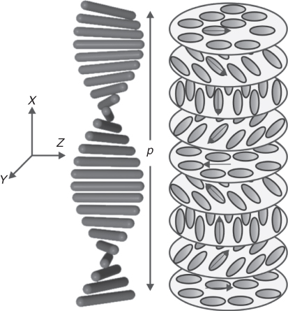
ChNLC consist of molecules with twisted alignment across the cell [1–3, 15, 16]. This results in a helical structure of finite pitch p, the latter defined as the distance along the helical axis after which the molecular orientation has turned by an angle 2π (Fig. 12.1). The ChNLC periodicity is p/2 as directors ![]() and
and ![]() are equivalent (for nonpolar molecules). Chirality can be induced by mixing a nematic liquid crystal with a chiral dopant. The pitch p of such a mixture can be easily modified because it depends on the concentration η of the chiral dopant: p = 1/(Hη), where H is the helical twisting power determined by the chemical structure of the chiral material [2, 16]. In the investigated ChNLC cells, the molecular director is parallel to the surrounding glass plates (interfaces) and twisted within the layer thickness. A similar orientation can be obtained for TNLCs, where the NLC molecules are anchored parallel to the glass plates, and these plates are mutually rotated by some angle. However, the maximum rotation in TNLCs is π/2, that is, corresponding to p/4.
are equivalent (for nonpolar molecules). Chirality can be induced by mixing a nematic liquid crystal with a chiral dopant. The pitch p of such a mixture can be easily modified because it depends on the concentration η of the chiral dopant: p = 1/(Hη), where H is the helical twisting power determined by the chemical structure of the chiral material [2, 16]. In the investigated ChNLC cells, the molecular director is parallel to the surrounding glass plates (interfaces) and twisted within the layer thickness. A similar orientation can be obtained for TNLCs, where the NLC molecules are anchored parallel to the glass plates, and these plates are mutually rotated by some angle. However, the maximum rotation in TNLCs is π/2, that is, corresponding to p/4.
Figure 12.1 Orientational order in chiral nematic liquid crystals.
The expression for the free energy of deformed ChNLCs is quite similar to that in NLC, and its density takes the form [1–3, 15, 16]
12.1 ![]()
where Kii are the elastic (Frank) constants for the three basic spatial distortions of the molecules. In the term related to a twist deformation, the parameter G = 2π/p describes chirality (in nematics G = 0). Energy minimization in unperturbed ChNLCs leads to ![]() , which can be fulfilled for example, for a director
, which can be fulfilled for example, for a director ![]() with the orientation angle θ = θ0 + Gx. Such an orientation corresponds to a helical structure with an axis along the x direction (as in Figure 12.1).
with the orientation angle θ = θ0 + Gx. Such an orientation corresponds to a helical structure with an axis along the x direction (as in Figure 12.1).
External fields and surface interactions can easily deform the initial helical configuration. The electrical permittivity of ChNLCs for fields parallel to the helical axis is different from the average permittivity in perpendicular directions. Therefore, an external electric field also causes the reorientation of the whole helical axes [17–19]. It should be noted that the deformation occurs in two stages: first, the molecules are tilted toward the electric field direction and then, untwisting of the helical structure occurs.
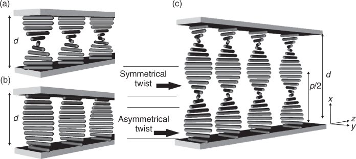
Optical spatial solitons or nematicons are investigated in configurations in which a light beam propagates parallel to the glass plates. We assume a beam propagating in the z-direction with a dominating Ey component of the electric field (as in Figure 12.2). For light polarized along y, the refractive index varies across the cell from the ordinary value no in those planes in which the molecules are parallel to the z-axis (i.e., where θ = π/2) to the extraordinary value ne in those where the molecules are parallel y (θ = 0). This can be compared to light propagation in a graded index waveguide. Therefore, the light is guided in a thin layer where θ = 0. By acting on the anchoring conditions, guiding index layers along x can be formed within the cell thickness, with location depending on θ at the glass/NLC interface and on the pitch p. For anchoring conditions such that θ0 = π/2, the largest refractive index is at the edges of the cell: if the refractive index of the glass is lower than the extraordinary index ne, the beam is guided at the NLC/glass boundary, partially extending into the isotropic medium (glass) and partially into the twisted liquid crystals. The asymmetry in molecular twist causes the appearance of beam walk-off.
Figure 12.2 Configuration of (a) symmetrically and (b) asymmetrically twisted TNLCs; (c) configuration of ChNLC layers with the indication of potential input beams.
12.3 Theoretical Model
The problem of light propagation in TNLCs and ChNLCs is quite complex, and its quantitative description requires an exact treatment of electromagnetic fields in anisotropic media [20]. However, for a qualitative description, the behavior of a light beam propagating in ChNLCs can be simply described by using the following approximated model [21–23]. This model assumes that the beam profile in the x-direction is invariant during propagation, that is, it assumes that the beam is guided by the linear waveguide created by the pitch. The results are in good agreement with experiments, and the description is adequate for both chiral and twisted structures.
The optic axis changes across the ChNLC cell, generally implying that all components of the electromagnetic fields are nonzero, even for linearly polarized input beams. However, only Ey and Ez cause molecular reorientation in the yz-plane. Along x, when the beam width ensures a good overlap with the guided mode (i.e., for a proper ratio of pitch and beam waist), the beam does not diffract appreciably in that direction. In this case, it can be assumed that the reorientation of the molecules is only in the yz-plane and is mainly connected with the twist deformation. Consequently, the electric permittivity tensor has the components ε xy = ε yx = ε xz = ε zx = 0 and ![]() . In this case, Maxwell's equations for monochromatic electromagnetic waves lead to
. In this case, Maxwell's equations for monochromatic electromagnetic waves lead to
![]()
where k0 = ω/c is the vacuum wave number.
For the beam propagating in the z-direction, it is convenient to introduce the ansatz
12.3 
where ϕ(x)exp(iωt − ik0Nz) and ψ(x)exp(iωt − ik0Nz) are components of the planar waveguide mode with an effective refractive index N. The modal envelopes ϕ(x) and ψ(x) fulfill the equations
12.4 ![]()
12.5 ![]()
where ε (0) is the electric permittivity corresponding to the initial orientation of the nematics. In the presence of such fields, the Euler–Lagrange equation for energy minimization has the form
12.6 ![]()
12.7 ![]()
where
is the optical anisotropy of the electric permittivity. Reorientation changes the local value of the electric permittivity tensor, which depends on the orientation angle θ as ![]()
12.8 ![]() .
.
For the paraxial approximation electric field components of the light beam Ez ![]() Ey, the slowly varying complex amplitude A fulfills the equation obtained from integration of Equation 12.3 over the cross section
Ey, the slowly varying complex amplitude A fulfills the equation obtained from integration of Equation 12.3 over the cross section
12.9 ![]()
where the coefficients γ1 and γ2 depend on the orientation angle θ as
12.10 ![]()
12.11 ![]()
At low optical power (the linear case), the coefficients γ have initial values equal to γ(0). As light intensity increases (the nonlinear case), the dominant Ey component of a linearly polarized beam induces reorientation in the yz-plane. The liquid crystal molecules are forced to reorient parallel to the electric field, which increases the γ1 coefficient. It modifies the diffractive broadening of the beam in the y-direction, whereas ![]() is responsible for self-focusing of the beam and the creation of a spatial soliton. It should be noted that the coefficient γ1 has a saturable form and can be calculated for a given liquid crystal layer, as shown in Figure 12.3a.
is responsible for self-focusing of the beam and the creation of a spatial soliton. It should be noted that the coefficient γ1 has a saturable form and can be calculated for a given liquid crystal layer, as shown in Figure 12.3a.
Figure 12.3 Dependence of nonlinear coefficients (a) γ1 and (b) γ2 on light intensity. The calculations were performed for TNLC films with orientation θ = θ0 + πx/2d and thickness d = 5 μm for different orientations at the boundary θ0. Increasing θ0 causes the beam to propagate farther from the cell boundary, that is, the configuration becomes more symmetric.
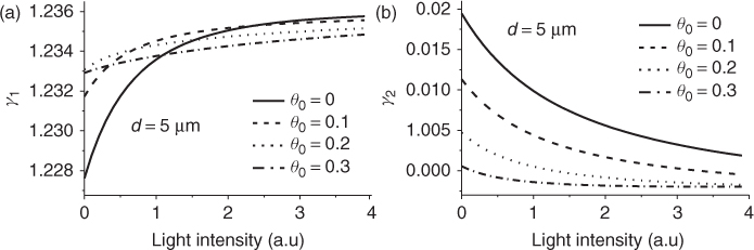
The second nonlinear coefficient γ2 is responsible for beam walk-off. This coefficient is zero in the symmetric case, that is, when the light beam profile ψ is symmetrically located around the layer in which θ = 0. This occurs with beams propagating inside the cell. If the beam is guided at the cell boundary (partially in the glass plate), the coefficient γ2 ≠ 0 defines the walk-off angle. In such a case, at low intensities, γ2 is the largest, and an increase in intensity causes a decrease in γ2 (as shown in Figure 12.3b). It means that for higher intensities, the beam walk-off is smaller, that is, the beam direction changes with light power (Chapter 11).
12.4 Experimental Results
12.4.1 Nematicons in a Single Layer
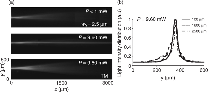
Self-focusing has been observed in a ChNLC cell filled by capillary effect with 6CHBT (4-trans-4′-n-hexyl-cyclohexyl-isothiocyanatobenzene) doped with a chiral material. 6CHBT possesses low absorption and high nonlinear response [24, 25], with refractive indices no = 1.51 and ne = 1.67 in the near infrared. The sample consisted of two glass plates glued together, with a gap controlled by a spacer. An alignment layer was deposited on the top plate to control the alignment of the liquid crystal molecules. The beam propagation in the cell was observed with a microscope objective and a CCD camera. The thickness of the cell was 50 μm, and the pitch of the ChNLC was about 25 μm. The long molecular axes were approximately parallel to the plane of the layers constituting the helical structure. The input beam waist was estimated to be about 2 μm by measuring the divergence during linear propagation in the NLC. Typical experimental results obtained with a Ti:Sapphire laser (λ = 793 nm) are presented in Figure 12.4 [26, 27]. Increasing the input power led to self-focusing and, finally, for an average power P = 9.6 mW, a spatial soliton was formed. The solitary beam had a transverse intensity distribution that remained unchanged after a propagation distance of about 3 mm (i.e., over 80 times the Rayleigh length).
Figure 12.4 Experimental results of spatial soliton creation in ChNLC layer for Ti:Sapphire laser: (a) light beam propagation for different inputs of light power (marked on photos) and centrally launching light beam, the last picture was taken for TM polarization; (b) light intensity profiles for different values of propagation distance.
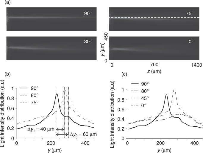
Owing to the finite thickness of each layer in the chiral structure, self-focusing can balance diffraction and give rise to self-trapped solitons only in a limited waist range [22]. Owing to structural anisotropy connected with chiral orientation, the beam walks-off from the initial direction of propagation while changing its polarization. Indeed, as shown in Figure 12.5, crossing from the TE-like to TM-like polarization causes the nematicon to propagate in different directions. However, for the TM-like polarization (for which the Freedericksz threshold prevents nematicon formation), the light beam propagates again along the z-axis.
Figure 12.5 (a) Experimental results showing beam walk-off by changing the polarization of the input beam. (b) Normalized light intensity profiles for three different polarizations for which the soliton changed its direction. (c) Normalized light intensity profiles for different polarizations switching from TE to TM-like.
12.4.2 Asymmetric Configuration
It should be noted that beam walk-off was also observed in asymmetrically twisted liquid crystals [28–30]. Typical pictures are presented in Figure 12.6a. First, light propagation in a homogeneous medium was investigated to verify that the beam was launched parallel to the y-axis. This was achieved by applying an external field, as an applied field with Ey polarization renders the medium homogeneous. Next, without an external electric field, the direction of beam propagation was changed, showing walk-off. In the linear case, when the light power was too low to induce reorientation, beam diffraction was observed. Increasing the power modified the twisting angle and increased the effective refractive index. Light started to change its direction of propagation and eventually created a solitary wave via self-focusing. The beam was guided close to the TNLC/glass boundary. As a consequence, the effective direction of the birefringence axis was not perpendicular to the initial beam direction, showing walk-off.
Figure 12.6 Experimental results on nematicon creation with an argon laser (λ = 514 nm) beam in asymmetrically configured TNLCs. (a) Beam propagation for various input powers (marked on photos) and (b) normalized intensity profiles for various propagation distances and powers.
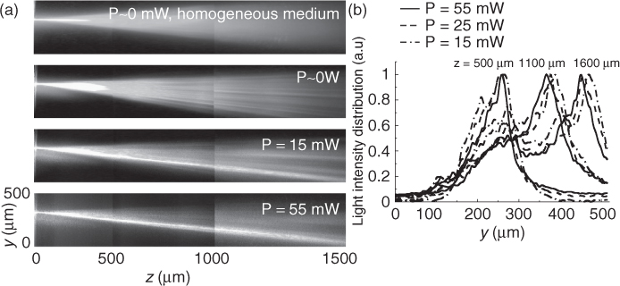
A comparison of size and shape of such a nematicon for various optical powers and at different distances are presented in Figure 12.6b. The intensity cross section of the scattered light was normalized to its maximum value. The size and shape of the obtained nematicons do not change significantly with increasing input power. However, an increase in power can modify the walk-off. The changes in beam direction versus power are weak but measurable. Effectively, at a distance of 1 mm, the beam can change position by approximately 20 μm as the power goes from 15 to 55 mW.
12.4.3 Multilayer Propagation
A light beam propagates in the region where the ChNLC molecules are parallel to the electric field. The twist is periodic versus the cell thickness, which implies that there are a few high-index regions where the beam can propagate. The number of such layers is determined by the cell thickness and the chiral pitch: it corresponds to 2d/p.
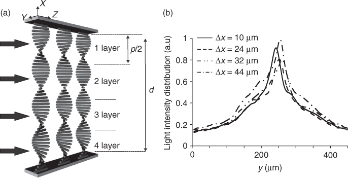
In this configuration, the width of the cell (d = 50 μm) and the ChNLC pitch (p = 25 μm) are such that there are four layers with molecules oriented in the same way (Fig. 12.7a). As a result, there are four layers with a thickness of about 12 μm in which nematicons can be excited independently [26, 27]. By changing the vertical position along the cell, it is possible to independently launch as many solitons as the number of layers in the structure. The vertical position in a ChNLC cell is controlled by means of a microscope slide with micrometric patterns fixed to the (x, y, z) stage and a second CCD camera mounted at the butt of the cell.
The vertical position of the ChNLC cell was changed for a defined TE-like polarization and input power high enough (about 10 mW) to form nematicons. Typical results are shown in Figure 12.7b for the input positions marked on the photos. The position Δx = 0 corresponds to a light beam propagating at the boundary between a glass plate and an NLC. A nematicon is formed in the first layer marked Δx = 10 μm and can be generated in each of the subsequent layers. Indeed, four nematicons were formed in distinct layers, about 10–12 μm away from each other.
Figure 12.7 (a) Schematic configuration of the chiral nematic liquid crystal cell with marked layers and (b) normalized intensity profiles for each position and after a propagation distance Δz = 1 mm.
12.4.4 Influence of an External Electric Field
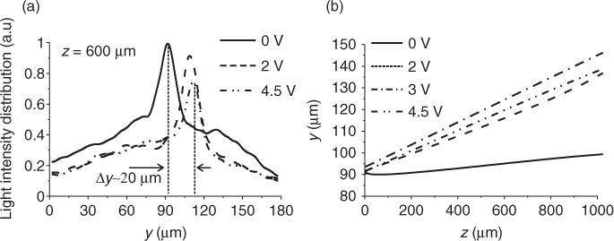
In a separate set of experiments, the influence of an external electric field on nematicon propagation was also investigated [31, 32]. An electric field (voltage) along the x-axis, thus parallel to the helix axis, leads to a bend deformation and director reorientation in the xy-plane. When a nematicon was generated in one of the middle guiding layers (for an input power of 15.4 mW and λ = 514 nm), it induced a channel waveguide with confinement along y. Applying an electric field along x changed the director orientation, and consequently, the soliton started to propagate at some angle to the z-axis. Figure 12.8a shows such a case corresponding to P = 15.4 mW and measured over a distance of z = 600 μm. A further increase in the electric field at fixed optical power increased the relative contribution of the electrically induced reorientation and destroyed the helical structure. As a result, the beam did not follow the molecule orientation, resulting in linear diffraction. Figure 12.8b plots the soliton trajectory as the voltage varies from 0 to 4.5 V. The displacement changed by 20 μm at a distance z = 600 μm. The maximum steering was estimated to be about ![]() , which is comparable with the birefringent walk-off in this material (the maximum walk-off was calculated to be
, which is comparable with the birefringent walk-off in this material (the maximum walk-off was calculated to be ![]() ).
).
Figure 12.8 Experimental results showing (a) the normalized light intensity distribution for three voltages for which the soliton changed direction and (b) nematicon trajectory for various applied voltages.
Furthermore, when the soliton propagated in the guiding layers nearest to the boundaries, the voltage required for steering shifted to higher values. This is caused by the fact that the anchoring conditions strongly inhibit molecular reorientation. In the middle layers, the director orientation changes are much less affected by the boundary conditions.
The polarization dependence of an input beam on steering was also investigated [31]; it was found that a change in input polarization alters the soliton direction for given beam, layer, and electric field. Changing the polarization causes the nematicon to propagate in a different direction relative to the z-axis. For an input polarization along y and a voltage of approximately 3.5 V, the beam propagates at an angle to the z-axis as a consequence of reorientation of the molecules. Changing the input polarization but keeping the voltage constant makes the beam propagate at an angle smaller than the z-axis.
Usually, in these kinds of experiments, one can see a diffractive background. This occurs because the field-induced reorientation changes the direction of the extraordinary axis in the xy-plane by the tilt angle, that is, a y-polarized input beam contains a small component along the new ordinary axis. With no voltage and sufficient power to create a nematicon, the wave has only an Ey component. With an external field, the nematicon propagates at a tilt angle relative to the yz-plane, with fields polarized along the new director. Furthermore, the small ordinary component diffracts in propagation.
12.4.5 Guiding Light by Light
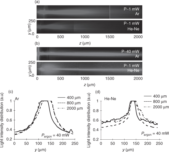
Similar to other nematicons, it was verified in TNLCs and ChNLCs that a solitary wave can confine a second low power probe, for example, from a He–Ne laser [23, 30, 32]. Nematicon propagation in a ChNLC or TNLC cell introduces changes in the refractive index distribution and leads to the formation of an optical waveguide (Chapter 1). This can be verified by injecting a second copolarized low-power probe, generally at a different wavelength. When the pump beam diffracts, the probe beam diffracts as well (Fig. 12.9a). When a high-power TE-polarized beam (from an argon laser, in this case) forms a spatial soliton, the copropagating low-power probe is also confined (Fig. 12.9b). Moreover, the probe follows exactly the direction of the soliton. The pump beam causes a focusing “lensing” effect, and the probe becomes increasingly confined, too.
Figure 12.9 Spatial soliton and optically induced waveguide in a ChNLC cell. (a) A linearly diffracting pump beam from an Ar laser and the corresponding propagation of a probe He–Ne beam, (b) soliton propagation for a high power Ar beam and the corresponding nondiffractive propagation of a probe beam, (c,d) normalized light intensity profiles at various propagation distances for (c) high power Ar beam and (d) colaunched low power He–Ne probe beam. Flat tops of the intensity profiles are caused by saturation of the CCD camera.
12.4.6 Nematicon Interaction
The interaction between two identical nematicons was also verified in ChNLCs [27]. If two nematicons are launched close to each other in one layer, they can attract and merge into one single self-trapped beam. This happens because of the spatially nonlocal response of liquid crystals, analogous to former experiments in planarly aligned NLC cells, for example, References 33, 34 and Chapters 1–2.
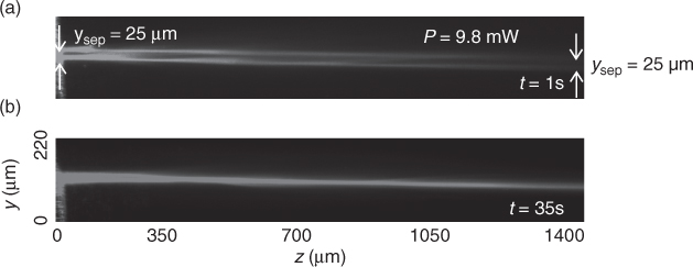
Two beams with w0 = 2 μm and separated by 25 μm were launched in one layer of ChNLC to form two identical nematicons. The refractive perturbation created by one beam diffuses and affects the other beam, causing two initially parallel solitons to attract one another. Depending on the initial geometry and the strength of nonlinearity, the two-beam interaction can have different outputs, that is, the solitons can either drag each other or pass through each other. The distance at which two solitons collide decreases with the input power. Solitons can not only interact with each other but also merge in a single self-confined beam. An example of time evolution of soliton–soliton interaction is also reported. Two beams of 10 mW propagate in the yz-plane with initial separation of 25 μm. Owing to the slow ChNLC time response, after illumination, no nonlinear behavior is visible and diffraction is observed with an overlap of the two waves as they propagate. After 1 s, two solitons are formed and propagate, maintaining their initial separation (Fig. 12.10a). In a few seconds, the solitons start to attract each other. Eventually, owing to the nonlocality of the NLC, after 35 s, they collapse into one beam (Fig. 12.10b) giving rise to a stable solution.
Figure 12.10 Time evolution of two interacting solitons of power 9.8 mW each. (a) Soliton formation after 1 s and separation equal to the initial one and (b) soliton fusion into one beam after 35s.
12.5 Discrete Diffraction
The results presented in the previous section were obtained in a single layer of the ChNLC cell. However, the interaction between solitons propagating in different layers is also possible [35]. Owing to the fact that the refractive index distribution changes periodically along the x-direction, that is, perpendicular to the glass plates, the analyzed cell can be treated as an array of planar waveguides. In such structure, it is possible to obtain the conditions for which the standard continuous diffraction is substituted by a discrete one by way of a coupling between waveguides side by side. Discrete diffraction has numerous interesting features (Chapter 10). In ChNLCs, a beam can diffract in two ways: continuously in one direction (in the yz-plane) and discretely in the other (in the xz-plane). The reorientational nonlinearity can suppress both types of diffraction and form nematicons.
To enable the experimental observation of discrete diffraction, the coupling length Lc defining the distance at which light switches from one waveguide to the adjacent one should be shorter than the sample length. The coupling length can be modified by changing the amplitude and period of the refractive index modulation, that is, by changing pitch and birefringence in ChNLCs. Low birefringence ChNLCs with a pitch p < 10 μm should be used, as presented in Figure 12.11a. Numerical simulations of beam diffraction in such configuration are shown in Figure 12.11c. Note that discrete diffraction does not depend on beam waist but on the refractive index modulation. To obtain comparable amounts of discrete (along x) and continuous (along y) diffractions, the initial beam size along y needs to be properly engineered (in the simulations, the input beam is much wider in y than in x ).
Figure 12.11 (a) Dependence of coupling length Lc on pitch in ChNLCs with two values of birefringence Δn; (b) dependence of the ratio between nonlinear refractive changes necessary to observe solitons and maximum possible changes in pitch for two ChNLCs with different birefringence; (c–e) numerical simulations of beam propagation in ChNLC with pitch p = 5 μm and birefringence Δn = 0.08: diffraction in the xz-plane (left) and in the yz-plane (right) for (c) the linear case (power P = 1mW); (d) nonlinear case (P = 200mW) for initial beam size 1 μm × 4 μm (FWHM); (e) nonlinear case for beam size 1 μm × 8 μm.
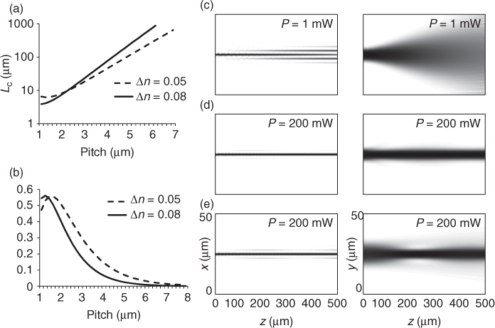
The creation of spatial solitons requires an increase of refractive index, which must be higher for shorter coupling lengths. In the presence of reorientational nonlinearity, the maximum changes in refractive index are limited by the birefringence. The ratio between the nonlinear index changes necessary to create solitons and the maximum possible changes versus pitch is graphed in Figure 12.11b. A lower ratio requires lower reorientation; in turn a lower input power is necessary to form nematicons. As a consequence, pitch and birefringence cannot be too small. In addition, for low birefringence ChNLCs, the elastic constants are larger than in 6CHBT. Keeping in mind the previous discussion, the powers necessary to excite discrete nematicons are much larger than in the configurations discussed earlier.
The nematicon shown in Figure 12.11d was generated by a beam diffracting with comparable divergences in both dimensions, that is, its size in y was chosen so that Rayleigh and coupling lengths were equal. However, if these two divergences were different, the creation of spatial solitons would be more difficult (as in the example in Figure 12.11e) and sometimes even impossible.
In summary, discrete nematicons seem to be very peculiar of ChNLCs but require larger powers and more accurately controlled excitation conditions than standard nematicons.
12.6 Conclusions
TNLC and ChNLC form convenient geometry for creation of spatial solitons. They do not need an external electric field, and optimization of nematicon parameters can be done by choosing the pitch and the birefringence of NLCs. The properties of observed solitons are typical for nematicons. They can also be easily steered by external fields, by other beams, as well as by changing the polarization or light power. The prospective properties of ChNLCs are connected with the existence of multiple-layered structures created by periodical orientation of molecules. For high birefringent ChNLCs, it allows to propagate independent nematicons in different positions across the cell. On the other hand, for low birefringent ChNLCs it can be an interesting structure for application of discrete diffraction. This, among others, can be the basis of three-dimensional elements for light beam switching and routing.
Acknowledgments
We are grateful to Edward Nowinowski-Kruszelnicki, Marek Sierakowski, Katarzyna Jaworowicz, Michal Kwasny, Katarzyna Rutkowska, and Filip Sala for extensive contributions to this work. This work was supported financially by the National Science Centre.
1. P. G. de Gennes and J. Prost. The Physics of Liquid Crystals, 2nd edn. Oxford University Press, London, 1995.
2. D. K. Yang and S. T. Wu. Fundamentals of Liquid Crystal Devices. Wiley, New York, 2006.
3. I. C. Khoo. Liquid Crystals, 2nd edn. Wiley, New York, 2007.
4. E. Braun, L. P. Faucheux, and A. Libchaber. Strong self-focusing in nematic liquid crystals. Phys. Rev. A, 48:611–622, 1993.
5. D. W. McLaughlin, D. J. Muraki, M. J. Shelley, and X. Wang. A paraxial model for optical self-focussing in a nematic liquid crystal. Physica D, 88:55–81, 1995.
6. M. Warenghem, J. F. Henninot, and G. Abbate. Non linearly induced self waveguiding structure in dye doped nematic liquid crystals confined in capillaries. Opt. Express, 2:483–490, 1998.
7. M. A. Karpierz, M. Sierakowski, M. Swillo, and T. R. Wolinski. Self focusing in liquid crystalline waveguides. Mol. Cryst. Liq. Cryst., 320:157–163, 1998.
8. M. A. Karpierz, in Soliton Driven Photonics, eds. A. D. Boardman and A. P. Sukhorukov, Kluwer, Dordrecht, Netherlands, p. 41, 2001.
9. M. A. Karpierz. Solitary waves in liquid crystalline waveguides. Phys Rev. E, 66:036603, 2002.
10. A. Piccardi, A. Alberucci, and G. Assanto. Soliton self-deflection via power-dependent walk-off. Appl. Phys. Lett., 96:061105, 2010.
11. A. Piccardi, A. Alberucci, and G. Assanto. Self-turning Self-confined light beams in Guest-Host media. Phys. Rev. Lett., 104:213904, 2010.
12. M. Peccianti, G. Assanto, A. De Luca, C. Umeton, and I. C. Khoo. Electrically assisted self-confinement and waveguiding in planar nematic liquid crystal cells. Appl. Phys. Lett., 77:7–9, 2000.
13. G. Assanto and M. Peccianti. Spatial solitons in nematic liquid crystals. IEEE J. Quantum Electron., 39:13–21, 2003.
14. M. Peccianti, C. Conti, G. Assanto, A. De Luca, and C. Umeton. Routing of highly anisotropic spatial solitons and modulational instability in liquid crystals. Nature, 432:733–737, 2004.
15. P. Oswald and P. Pieranski. Nematic and Cholesteric Liquid Crystals: Concepts and Physical Properties Illustrated by Experiments. Taylor & Francis, London, 2005.
16. H. S. Kitzerrow and C. Bahr. Chirality in Liquid Crystals. Springer, New York, 2001.
17. R. B. Meyer. Effects of electric and magnetic fields on the structure of cholesteric liquid crystals. Appl. Phys. Lett., 12:281–283, 1968.
18. A. Chanishvili, G. Chilaya, and D. Sikharulidze. Electro-optic effect in an optically active nematic chiral liquid crystal structure. Appl. Opt., 33:3482–3485, 1994.
19. L. M. Blinov. Electro-optical effects in liquid crystals. Sov. Phys. Usp., 17:658, 1975.
20. F. A. Sala and M. A. Karpierz. Numerical simulation of beam propagation in a layer filled with chiral nematic liquid crystals. Photon. Lett. Pol., 1:163–165, 2009.
21. G. Assanto and M. A. Karpierz. Nematicons: self localised beams in nematic liquid crystals. Liq. Cryst., 36:1161–1172, 2009.
22. U. A. Laudyn, M. Kwasny, K. Jaworowicz, K. Rutkowska, and M. A. Karpierz. Self focusing and nematicons in chiral nematic liquid crystals. Proc. SPIE, 7141:71410F, 2008.
23. U. A. Laudyn, K. Jaworowicz, and M. A. Karpierz. Spatial solitons in chiral nematics. Mol. Cryst. Liq. Cryst., 489:214–221, 2008.
24. W. Baran, Z. Raszewski, R. Dabrowski, and J. Kedzierski. Some physical properties of mesogenic 4-(trans-4′-n-Alkylcyclohexyl) isothiocyanatobenzenes. Mol. Cryst. Liq. Cryst., 123:237–245, 1985.
25. R. Dabrowski, J. Dziaduszek, and T. Szczucinski. Mesomorphic characteristics of some new homologous series with the isothiocyanato terminal group. Mol. Cryst. Liq. Cryst., 124:241–257, 1985.
26. U. A. Laudyn, M. Kwasny, and M. A. Karpierz. Nematicons in chiral nematic liquid crystal cell. Appl. Phys. Lett., 94:091110, 2009.
27. U. A. Laudyn, M. Kwasny, and M. A. Karpierz. Nematicons interaction in chiral nematic liquid crystals. Mol. Cryst. Liq. Cryst., 527:92–97, 2010.
28. M. A. Karpierz, M. Sierakowski, and T. R. Woliñski. Light beam propagation in twisted nematics nonlinear waveguides. Mol. Cryst. Liq. Cryst., 375:313–320, 2002.
29. K. Jaworowicz, K. A. Brzdakiewicz, M. A. Karpierz, and M. Sierakowski. Spatial solitons in twisted nematic layer. Mol. Cyst. Liq. Cryst., 453:301–307, 2006.
30. U. A. Laudyn, M. Kwasny, K. Jaworowicz, K. A. Rutkowska, M. A. Karpierz, and G. Assanto. Nematicons in twisted liquid crystals. Photon. Lett. Poland, 1:7–9, 2009.
31. U. A. Laudyn, M. Kwasny, and M. A. Karpierz. Electric-field steering in soliton direction of propagation in chiral nematic liquid crystals. Opt. Commun., 283:1463–1466, 2010.
32. U. A. Laudyn, M. Kwasny, and M. A. Karpierz. Properties of spatial solitons in chiral nematic liquid crystal cells. Photon. Lett. Poland, 1:157–159, 2009.
33. M. Peccianti, K. A. Brzdakiewicz, and G. Assanto. Nonlocal spatial soliton interactions in bulk nematic liquid crystals. Opt. Lett., 27:1460–1462, 2002.
34. M. Peccianti, C. Conti, G. Assanto, A. De Luca, and C. Umeton. All optical switching and logic gating with spatial solitons in liquid crystals. Appl. Phys. Lett., 81:3335–3337, 2002.
35. M. Kwasny, U. A. Laudyn, P. Jung, and M. A. Karpierz. Possibility of discrete beam propagation in chiral nematic liquid crystal. Photon. Lett. Poland, 1:160–162, 2009.