
9
Verifying the Implementation Step by Step
9.1. Introduction
In this chapter, we will discuss the verification carried out at different stages of the realization (implementation) of a given system. We recall that the signification of the term “verification” depends on the standard or the norm with which it is used. Here, we work within the framework of the ARP4754A recommendation as we did for the validation, and in order to remain consistent, within a validation/verification cut.
Consequently, the concept of verification only refers to the different stages of the implementation of a given type of systems, and there is no sense in discussing the verification of a software specification in relation to the system specification it depends on, as in the case of the DO-178C [EUR 12].
First, we will recall what the ARP4754A states about the verification process, as well as its goal and the means that this recommendation encourages and applies. Second, we will then see how these goal and means can be declined within the framework of the systems engineering approach based on the models we propose, namely the Property Model Methodology (PMM).
9.2. The verification process according to the ARP4754A
9.2.1 Goal of the verification
The ARP4754A recommendation defines the verification as a process by which we ensure that all the levels of implementation of a given type of systems are consistent with the requirements specified to them and how, once integrated and installed, such systems are consistent with their own specification. Its goal is to establish that, for a given level of verification rigor, related to the severity of associated failure consequences, the implementation of a system is free of errors. Verification goal and validation goal are complementary, and the conjunction of both should ensure that the implemented and installed systems are the right systems1, as shown in Figure 8.1.
9.2.2 Verification methods
Figure 9.1. Implementation verification process regarding specifications
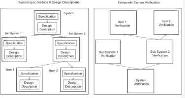
Conversely to the validation process, the ARP4754A recommends an ascending verification process by first verifying the compliance of the simplest components with their own requirements and then by verifying that the integration of these components is compliant with the corresponding requirements, and by gradually proceeding thus, up to the highest system level.
During these verification processes, the non-compliance of an implementation with its specifications, due to an implementation error, can be detected. This discrepancy should then be treated according to the rules of a controlled process managing corrections and modifications.
The approach proposed by the ARP4754A to verify an implementation regarding the requirements {Reqi}1≤i≤n allocated to it involves the construction of a verification matrix (or any other equivalent method) in which each requirement is referred to by a line.
Figure 9.2. ARP4754A verification process model
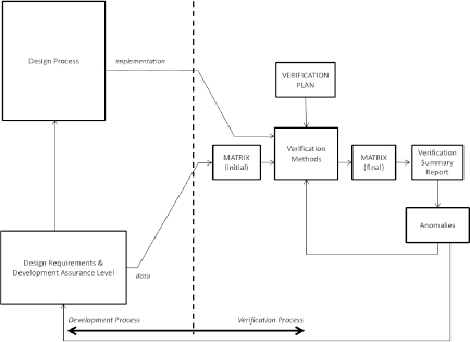
At the initial stage, for each of these lines (that is to say, for each requirement and each assumption) the stakeholders in charge of conducting the verification process propose, on the one hand, a level of rigor with which the verification process will be conducted and, on the other hand, the verification method or methods to be used.
Concerning the level of rigor expected of a verification effort, the ARP4754A associates (just as for the rigor in validation) the severity of risk the crew and passengers are exposed to, in case of a failure of the service provided by the system under consideration. The level of rigor of the implementation verification with regard to requirement allocated to a system whose failure would have catastrophic consequences (CAT) for the crew and passengers shall be maximal. Then the level of rigor can be gradually reduced if the consequences are hazardous (HAZ), major (MAJ), minor (MIN) and, finally, no safety effect (NSE) according to a classification well established by regulation.
The verification plan, which is the entrance point of the verification activities, identifies, on the one hand, the verification methods that will be used either on their own or in a combined manner. On the other hand, it defines, depending on the intended level of rigor, the combination of methods required or advised to successfully carry out the verification process.
The ARP4754A identifies the following verification methods (implementations in relation to the requirements allocated to them):
We will note that the ARP4754A does not clearly state the nature of the design products, whether it should be architectural drawings or descriptions of the intended behavior; the expression “design verification”, present in the ARP4754 version, has disappeared from the ARP4754A.
9.3. The verification process according to the property model methodology
9.3.1 Objects to be verified
Like the ARP4754A, the PMM introduces a verification process, which is applied to the implementation. This verification process covers, therefore, all the implementation phases and all the products resulting from these phases. This verification is of course carried out in relation to the corresponding system specification models.
The implementation phases include:
Design (descriptive models) or physical products are matched to the implementation phases and undergo a verification process in relation to the corresponding specification models:
9.3.2 Goal of the verification
Like the ARP4754A, when using the PMM, the goal of the verification is to ensure that the products of each stage of the implementation are compliant with the requirements they support.
Ideally, the verification could have aimed to demonstrate that for the following levels:
Unfortunately, this absence of errors at each implementation stage cannot generally be established in absolute terms. It can only be a more or less corroborated conjecture depending on the rigor of the verification process used. However, an implementation always remains at the mercy of a non-detected error because none of the verifications carried out have uncovered it. Nevertheless, the verification approach presented here enables the reduction of this risk to an acceptable level, with regard to the potential consequences of such an error.
We also see that errors can be introduced in each implementation phase of a system of the type considered, which ruins all hope of removing this or that verification phase. Such a removal would only result in a displacement of the problems such as the discovery of a design error during the verification of the installation.
9.3.3 Verifying the design
In this section, we will focus on the verification of the design models; we will discuss on other implementation phases in section 9.3.4.
Let us consider a composite system model such as the one presented here.
Figure 9.3. Composite system model. For a color version of this figure, see www.iste.co.uk/micouin/MBSE.zip
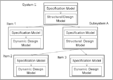
We suppose that all the specification models have been validated, with the required level of validation rigor (see Chapter 8, section 8.3.3 and 8.3.4), at each level of this system model.
We will use the system in Figure 9.3 as an example; we will then carry out the verification of the design model by starting with the lowest level objects:
PMM does not put aside any methods of verification considered by the ARP4754A (section 9.2.2). However, it favors simulation as a verification method at design level, just as it considers simulation to be the main method of cost and deadline control, and consequently the main method to reduce the complexity of a system development.
By carrying out a design verification by simulation, we have the opportunity to detect the design errors early, which is always preferable.
Simulation presents two advantages for design verification. First, it is an early method of verification in comparison to methods, such as tests, which are belated methods of verification2. Second, it offers an objective method to evaluate the design model, whereas other early methods based on literary descriptions (such as analyses and inspections) depend more on the people carrying them out. Initially, a system design model can contain design errors, but it is objective and this objectivity will enable us to consider it free of errors, with a sufficient degree of confidence, after having carried out a verification effort proportional to the potential risks.
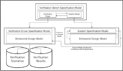
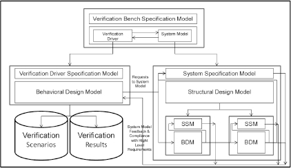
Verification by simulation implies setting up a verification workbench involving, on the one hand, a system model and, on the other hand, a verification driver as shown in Figure 9.4.
The verification driver is an artificat that submits verification cases, chosen from the verification scenarios, to the systems model, which we want to verify the design. The model reacts to the verification cases submitted to it at each simulation cycle. The design model computes its outputs as a function of the inputs submitted to it and also, more often, as a function of observable states. During that time, the specification model ensures that the inputs are compliant with the assumptions made and the outputs (and observable states) are compliant with the specified requirements.
The question of verification scenarios and the verification effort required will be discussed below.
Figure 9.4. System model verification bench
When a design model is not an equation design model (EDM) but a behavioral design model (BDM), we can legitimately expect the specification model to detect non compliances in relation to the requirements (that is to say, design errors), when the verification scenarios are submitted to the system model. It is appropriate to treat these discrepancies according to the rules of a controlled correction and modification management process, until the specification model stops detecting discrepancies.
Furthermore, if the verification scenarios comply with the effort of verification rigor intended, and that no non compliances are detected, the design model can then be considered as free of design errors.
The system design model being verified is generally a composite model whose most detailed elements are BDMs like the one presented in Figure 9.5.
Figure 9.5. System model integration verification bench
If we adopt the gradual and ascending approach to verification, which is presented above, the lowest level BDMs are verified first until they can be considered compliant with their respective specification models. Once this step is complete, the integrated models can be verified.
Furthermore, if the verification scenarios comply with the effort of verification rigor intended and no non-compliances are detected, then the design model can gradually be considered free of integration design errors up to the global system level.
Considerations related to the rigor and validation effort mentioned in section 8.3.5 of the previous chapter can be completely transposed to the design verification, to the verification effort and its rigor. Then, it is clear that the scenario definition strategies and verification cases of the different dynamic design models can be completely traced from those of scenarios and the validation cases.
Furthermore, we can, if we wish, integrally reuse the scenarios and validation cases, as scenarios and verification cases. If we wish, we can also complete them.
9.3.4 Verifying the other products of implementation
Unlike the design models, which are semiotic objects, the other products of implementation are material objects, mechanical parts, electro mechanic machines, chemical reactors, electronic components, hardware loaded with their software, electromagnetic communication systems, etc. They are the result of production, integration and installation processes, which can all be faulty.
Once each elementary component has been produced or acquired, it is verified. Then, the system integration process will involve assembling the different system elements in a pre-established order and verifying the compliance of the successive assemblies with the intermediary specifications up to the specifications of the system itself. This illustrated in Figure 9.6, inspired from the EIA 632.
Figure 9.6. EIA632-based system verification process
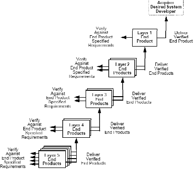
The possibility of an error, being inscribed in the material product at any phase of the implementation stages, imposes a verification, which is not carried out using models and simulation methods, but on material products by testing.
The test bench and the aircraft now replace the simulation workbench, and the hardware replaces the models. However, subject to possible adaptations to differences in support, the set of simulation scenarios and verification cases can be reused. This is especially true as the compliance with certain requirements can only be verified in the real world, such as calibration requirements and the worst-case execution time (WCET).
9.3.5 The contract theorem
This enables us to conclude with a fundamental theorem of systems engineering, which we could name the “contract theorem”.
Let Σ be a type of systems, defined by a specification model {Rqi}1≤i≤n, where each Rqi is a property-based requirement (including assumptions).
Suppose an architecture A, selected for Σ, is constituted of m subsystem types { σ1, .., σm} linked between each other following the endo-structure defined by A and that each requirement Rqi allocated to Σ is derived over different subsystems σj of Σ such that:
when A → Rqi ≤ Rqi,1∧..∧ Rqi,m (i), for all i belonging to [1, n],
We can then establish the following theorem:
Premises
Conclusion
9.4. Conclusion
The PMM enables the development of a verification strategy of the different stages of the implementation in relation to requirements fully compliant with the ARP4754A recommendation.
It enables the verification of all the design models of a systems model, ascending from the most detailed to the highest levels, and ensuring the compliance of the system design with the specification model, step-by-step, with a degree of confidence proportional to the rigor of verification effort developed.
The evidence of this design verification is established early by simulation, well before the components of the corresponding physical systems are realized.
It then enables the verification of all the production, integration and installation artifacts, ascending from the most elementary to the highest level, ensuring the compliance of the system implementation with its specification, step-by-step, with a degree of confidence proportional to the rigor of verification effort developed.
1 Right systems are those that are targeted and accepted by all the stakeholders.
2 As they are belated in the sequence of tasks, when the time comes for tests, most of the initial budget has already been used, leaving no room for change.