
10
Safety Engineering
10.1. Introduction
Most states1 impose that a level of protection should be provided by civil aviation to each citizen through the adoption of safety rules, and by measures that ensure that products, people and organizations respect these rules. This is the reason why aeronautical products2 are subject to certification to guarantee that they comply with the essential airworthiness requirements related to civil aviation, airworthiness being the aptitude of a civil aircraft to safely carry out its mission: transporting people.
In this chapter, we will discuss safety engineering carried out during the different phases of the development of a type of systems. We recall the signification of the term “safety” given by the ED79A/ARP4754A at page 9: safety is a state in which the risk is acceptable, whereas the term “risk” (p. 9) corresponds to the probability of occurrence of an event associated with its severity.
First, we recall what the ARP4754A says of the safety assessment process, the goal that this recommendation sets and the means that it advocates. We will then see how these goals and means can be declined within the framework of the systems engineering approach based on the models we propose, namely the property-model method.
10.2. The safety assessment process according to the ARP4754A
10.2.1. Goal of safety assessment process
Strictly speaking, the ARP 4754A recommendation defines the safety assessment as the process which, carried out jointly with other ARP4754A processes, enables us to ensure the compliance of an aircraft system with airworthiness requirements such as the 1309 requirement of the US Federal Aviation Regulations (FARs) or the EASA Certification Specifications (CSs). It relies on interpretative material produced by the regulatory authorities (e.g. Federal Aviation Administration (FAA) and EASA) such as the advisory circular (AC) 1309 in the US or then acceptable means of compliance (AMC) 1309 in Europe, and called “System Design and Analysis”.
Broadly, safety assessment is considered as a process with which we demonstrate the safety requirements, posited by the law, have correctly and completely been taken into account during the development of aircraft systems dedicated to civil aviation for the transport of persons and cargo.
Safety assessment is a process that establishes that the safety of persons (crew and passengers) is ensured in specified operation conditions and specified maintenance conditions of the system whose installation is certified, going from the identification of failure conditions of functions ensured by the system considered to the demonstration that the risks remain acceptable.
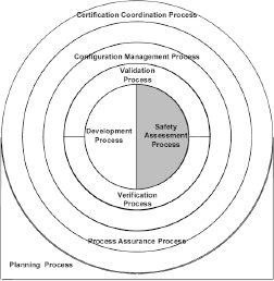
Figure 10.1. ARP4754A safety assessment process
10.2.2. Means to assess safety
First, the ARP4754A endorses the definitions provided by the interpretative material issued by authorities.
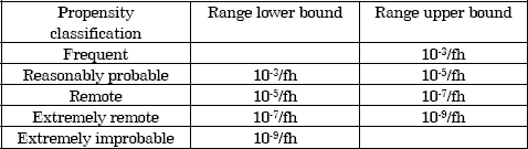
This interpretative material (for example, AC29.1309.b(1)) quantifies the propensity of failure conditions according to a scale of failure rate per flight hour, established as follows:
Table 10.1. Failure rate classification according to AC29.1309.b(1)
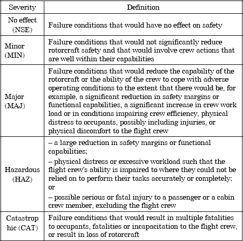
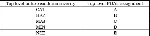
It also sets (for example, AC29.1309.b(2)) failure condition severity quantification criteria, ranging from “No Safety Effect” (NSE) to “Catastrophic” (CAT) and passing by “Minor” (MIN), “Major” (MAJ) and “Hazardous” (HAZ) according to a severity scale defined in Table 10.2.
Table 10.2. Failure condition severity definitions according to AC29.1309.b(2)
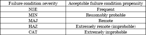
This interpretative material (AC29.1309.b(3)(ii)) then sets the acceptable levels of risk as shown in Table 10.3.
Table 10.3. Safety objectives for installed systems according to AC29.1309.b(3)(ii)
The interpretative material (AC29.1309.b(3)(iii)) determines also a technological operative rule according to which the safety objectives associated with CAT failure conditions are achieved if, on the one hand, (1) no simple failure can lead to a CAT failure condition, and if, on the other hand, (2) each CAT failure condition is extremely improbable (i.e. λ ≤10-9/fh).
Second, the ARP4754A extends through the concepts of functional/item development assurance level (FDAL/IDAL), concepts inherited from the ARP4754 recommendation (development assurance level (DAL)) and ED 12/DO 178 standards (software level) for software, and ED80/DO-254 [ED 00] (hardware design assurance level) for electronic components. A product development assurance process is a means for avoiding development errors and mitigating their consequences (in Chapter 8 (section 8.3) and Chapter 9 (section 9.3), we distinguished errors in specification, design, production, integration and installation). The rigor of this process is graduated in five levels (from the most rigorous (A) to the least rigorous (E)), and each level, a priori, corresponds, item by item, to the severity of the failure conditions caused by the product, as shown in Table 10.4.
Table 10.4. Top-level function FDAL assignment according to ARP4754A
The recommendation also proposes a set of technological operational rules that allow the assignation of the FDAL/IDAL, by taking into consideration the architectural characteristics of the system or the item under consideration (namely, Table 3, pp. 41 and 42 of the ED79A/ARP4754A).
Third, it systematizes the safety assessment process sketched out by the interpretative material (for example, AC29.A309.b(4)) by detailing the different analyses that should be conducted:
10.2.2.1. Functional hazard assessment
An FHA aims to examine the possible failures in functions (intended effects), first at the aircraft level, and then at the aircraft system level, to determine the severity of the consequences of these failures depending on the context in which they appear. The detailed manner of carrying out these FHAs is covered in the ARP4761 recommendation [SAE 96]. This last recommendation proposes (in annex A, p. 39) a format to present the results of an FHA, which are identified for:
10.2.2.2. Preliminary aircraft/system safety assessment (PASA and PSSA)
The preliminary safety assessment enables the derivation of safety objectives (or requirements) defined at the FHAs level and the assignation of derived safety requirements to the different architectural elements of the aircraft or the systems considered, namely the safety requirements assigned, on the one hand, to the structure and, on the other hand, to the components of the system. These quantitative3 and qualitative safety requirements allocated to the system structure are design requirements aiming to reduce risks. Preliminary safety assessment goes alongside the system design process:
10.2.2.3. Aircraft/system safety assessment (ASA and SSA)
Safety assessment aims to verify the safety objectives allocated to the functions at the FHA’s level and the safety requirements allocated to the different architectural elements of the aircraft or the system considered are effectively satisfied. This safety assessment goes with the verification process of the system implementation. The detailed manner of carrying out such safety assessments is covered in the ARP4761 recommendation (annex C, p. 45).
10.2.2.4. Common cause analysis
CCAs cover three types of analyses: CMAs, ZSAs and PRAs. These analyses all aim to detect the common causes that could ruin safety arrangements and falsify safety assessments based on these arrangements. The detailed manner of carrying out such CCAs is covered in the ARP4761 recommendation (annexes I, J and K, pp. 151, 156 and 159).
10.3. The safety assessment process according to the property model methodology (PMM)
10.3.1. Errors, faults and failures
In Chapter 2 (section 2.6), we have introduced the concepts of failure, fault and error. These concepts have been introduced in connection to those of function, behavior and structure of the Function-Behavior-Structure (FBS) framework (see section 2.3) as presented in Figure 10.2.
Figure 10.2. Failure, fault and error
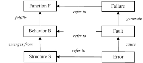
Failure: when a technological system operates in environmental conditions it has been designed for, it experiences a failure the instant it ceases to produce the intended effect on its environment, whether it be the loss of the required function or the faulty performance of that function.
Faults: a faulty behavior (or symmetrically, a faulty state) of a technological system is the more or less immediate cause of a failure, i.e. a loss or faulty performance of its function.
A failure, i.e. a loss or faulty performance of its function, is the consequence of one or more faulty behaviors (or symmetrically, faulty states) of the technological system under consideration.
Errors: faulty behaviors (or symmetrically, faulty states) originate in errors either in the structure or the components of the technological system or in the assessment of the environmental conditions.
Certain faults are said to be dormant, i.e. they remain unknown from the operator during a certain period of time. For example, an engine, a pump or even a valve can be in a faulty state, but this state remains hidden as they are at a standstill. The fault only reveals itself when this engine, pump or the command of this valve are activated. The built- in tests (BITs) and preflight tests are appropriate means for the detection of dormant faults.
In a system organized in multiple architectural levels, the notions of fault and failure are relative to the level under consideration. Thus, the failures of an aircraft are caused by simple or combined faults of the aircraft systems. These faults, considered as failures at the aircraft system level, are caused by simple or combined faults of the subsystems of the system under consideration.
Finally, we will note that the use of a technological system, in environmental conditions explicitly excluded from the usage domain, cannot lead to a failure of the technological system considered but constitutes an operation error.
10.3.2. FHA and interpretation of the 1309(b)(2)(i) requirements as PBRs
In the different regulations, the 1309 requirement requires the aircraft and system manufacturers to install systems whose failure cannot lead to an exposure of passengers and crew to unacceptable risks.
If we consider the FAR29 and its 1309(b)(2)(i) clause
FAR 29.1309 Equipment, systems, and installations.
(b) The rotorcraft systems and associated components, considered separately and in relation to other systems, must be designed so that
In the following passage, we will show that the interpretation of this airworthiness requirement in terms of property-based requirements (PBRs) entails carrying out an FHA.
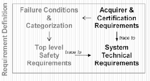
Expressed in the context of the EIA 632 requirement definition process, we will first examine the function failure conditions (failure of effects intended by the acquirer and the regulation) of the type of systems under consideration and then assess the severity of these failure conditions to set the safety requirements (top-level safety requirements), which should, if they are satisfied, render the risk acceptable.
Figure 10.3. EIA632 requirement definition process extended to safety aspects. For a color version of this figure, see www.iste.co.uk/micouin/MBSE.zip
The 1309(b)(2)(i) statement integrates sentences such as “the occurrence of any failure condition which would prevent the continued safe flight and landing of the rotorcraft” and expressions such as “extremely improbable”, which shall be interpreted according to interpretative material recalled in section 10.2.2 in the following way: i.e. catastrophic failure conditions shall have a probability of occurrence less than or equal to 10-9/fh.
System or item failure conditions are specific to the system or item under consideration. Furthermore, the severity of the consequences of the failure conditions on flight and landing safety depends on (1) the system or item under consideration, (2) the system or item failure condition and (3) assumptions on the environment of the system or item (by system or item environment, we mean the other systems in the aircraft, but also the aircraft environment itself, namely the ground, the meteorological conditions and other traffic).
Figure 10.4 illustrates this process in which the airworthiness requirement 1309(b)(2)(i) is assigned to a set (a priori, variable) of systems installed on board an aircraft, such as an aircraft flight control system (AFCS), a fly-by- wire system (FBWS) and an air data system (ADS).
Figure 10.4. Interpretation of FAR29.1309(b)(2) and systems FHA
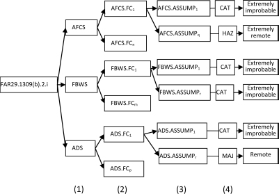
In this way, we consider, for example, an ADS, which provides an indication of the barometric altitude of the aircraft, among other air data. This indication of barometric altitude is provided to the crew and the AFCS (mainly in order to maintain a vertical separation between aircraft in the air space system) and possibly to other systems. If the aircraft evolves in instrument meteorological conditions (IMC), the provision of an undetected erroneous indication of the barometric altitude is a specific failure condition of the ADS. This failure condition is considered as CAT by the interpretative material (AC25.11A5). In the case considered, we can deduce the following PBR from the textual requirement FAR 29.1309.b(2):
PBR10: when AC.Flight_Condition=IMC →
val(ADS.MisleadingIndicatedAlt.propensity) ≤ 10-9/fh
In other words, we can deduce from the previous case that the interpretation of the textual requirement FAR 29.1309.b(2) is a conjunction of PBRs of the form:
PBRquant: when Assumpi
→ val(Systemi.FailureConditioni.propensity) ≤ λi
where Assumpi is an assumption made about the context (for example, the phase of the flight and the meteorological conditions) in which the failure condition FailureCondition can occur. System is a system likely to experience the considered failure condition FailureCondition, and propensity is the propensity of the system System to experience the failure condition FailureCondition, and λI is the maximum failure rate acceptable per flight hour. This enables us to specify the quantitative safety requirements assigned to the system under consideration as a conjunction of PBRs.
The interpretation of the FAR 29.1309 requirement, based on the ARP4754A, also allows us to interpret qualitative safety requirements, such as the FDAL, in terms of PBRs, assigned to the system under consideration.
PBRFDAL: val(Systemi.FDAL)=A (or B, C, D or E)
Furthermore, the interpretative material6 imposes additional requirements, for systems where failure conditions have CAT consequences, such as the requirement known as “fail safe concept”. This “fail safe concept” requires that a system continues producing the intended effects (its function) despite the occurrence of a single failure, which it shall tolerate.
Thus, to interpret the “fail safe concept” in terms of PBRs, the system’s intended behavior would have been previously specified in nominal conditions to then require the upholding of this intended behavior when a single failure occurs. We will illustrate this in the following example.
Consider a baro-altimeter system to be installed on board of an aircraft, which will ensure the transport of passengers according to the instrument flight rules (IFRs). In such conditions, regulation considers the loss of indication of the barometric altitude or even the indication of an undetected faulty baro-altitude as catastrophic. As imposed by the regulation, such failure conditions shall be extremely improbable, and therefore the failures rates per flight hour associated with these failure conditions shall be less than 10-9. In addition, the fail safe concept applies.
Figure 10.5. Baro-altimeter specification model. For a color version of this figure, see www.iste.co.uk/micouin/MBSE.zip
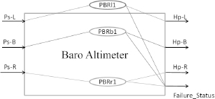
In a first attempt, a system providing two indications of the baro-altitude devised from two pairs of static ports was considered. This first lead was quickly abandoned because it did not guarantee the non-occurrence of an undetected faulty baro-altitude indication. As a second attempt, a system providing three indications of the baro-altitude (left, back up and right) devised from three pairs of static ports was kept. The model also proposes an observable state signaling the presence, or not, of a single failure.
This model supports four PBRs: PBRL1 concerning the indication of left altitude, PBRB1 concerning the indication of the backup altitude and PBRR1 concerning the indication of the right altitude (where f is a real defined function), and a fourth requirement PBRDisp1 about the dispersion of the three indications:
PBRL1:when Altimeter.Not(Failure_Status)→
HpL(t+200ms)=f(PsL(t));
PBRB1:when Altimeter. Not(Failure_Status)→
HpB(t+200ms)=f(PsB(t));
PBRR1:when Altimeter. Not(Failure_Status)→
HpR(t+200ms)=f(PsR(t)).
This means that we require that the value of the provided altitude indication at the left (respectively, back up, right) be calculated from the measured static pressure at the left (respectively, back up, right) port by using the function f with a maximum delay of 200 ms of the indication on the measure.
A fourth PBR is about the dispersion of provided altitude indications. It shall be less than or equal to 25 ft, in normal conditions.
PBRDisp1:when Altimeter. Not(Failure_Status)→
|HpL(t- HpB(t)| ≤25ft and |HpB(t- HpR(t)| ≤25ft and
|HpR(t- HpL(t)| ≤25ft
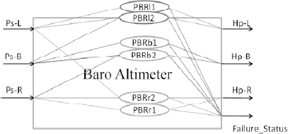
From there, the “fail safe concept” imposes that this system continues to produce the intended effects (that is to say it provides the three indications of the baro-altitude: left, back up and right) despite the occurrence of a single failure, which it shall tolerate.
In these conditions, the single failure tolerance supposes an extension of the specification model by adding three additional requirements, PBRL2 for the left indication, PBRB2 for the backup indication and PBRR2 for the right indication:
PBRL2:when Altimeter.SingleFailure→
HpL(t+200ms)=f(PsL(t))or f(PsB(t));
PBRB2:when Altimeter. SingleFailure→
HpB(t+200ms)=f(PsB(t)) or f(PsR(t));
PBRR2:when Altimeter. SingleFailure→
HpR(t+200ms)=f(PsR(t)) or f(PsL(t)).
In the same way, the dispersion requirement is extended to a single failure condition.
PBRDisp2:when Altimeter. SingleFailure→
|HpL(t- HpB(t)| ≤25ft and |HpB(t- HpR(t)| ≤25ft and
|HpR(t- HpL(t)| ≤25ft;
The requirements PBRL2, PBRB2 and PBRR2 are, respectively, less constraining than the requirements PBRL1, PBRB1 and PBRR1. Indeed, when a single failure occurs (we do not know which one), they allow the indications HpL (respectively, HpB, HpR) to be computed with the same constraints, not from a unique source (respectively, PsL, PsB, PsR), but from one or the other of the two sources PsL or PsB (respectively, PsB, or PsR, PsR or PsL). In other words, the tolerance to single failure will be carried out through a source diversification. In the same time, results dispersion has to be held (PBRDisp2 instead of PBRDisp1).
Figure 10.6. Fault-tolerant baro-altimeter specification model. For a color version of this figure, see www.iste.co.uk/micouin/MBSE.zip
10.3.3. PASA/PSSA and deriving safety requirements
As we saw previously, the safety requirements, be they quantitative or qualitative, are outcomes of the FHA of the aircraft/system functions and will be assigned to components and aircraft/system structure in the context of a PASA/PSSA, in the way it is synthesized in the ARP4754A and developed in the ARP4761 recommendation annex B.
In the following section, we will show that the derivation of safety requirements (quantitative or qualitative) with respect to a given design architecture amounts to leading a preliminary safety assessment (PASA/PSSA).
Expressed in the context of the EIA 632 process of solution definition, we will then examine the way in which the different qualitative and quantitative safety requirements can be derived and assigned to components and to the structure of the system under consideration to generate specified safety requirements.
Figure 10.7. EIA632 solution definition process extended to safety aspects. For a color version of this figure, see www.iste.co.uk/micouin/MBSE.zip
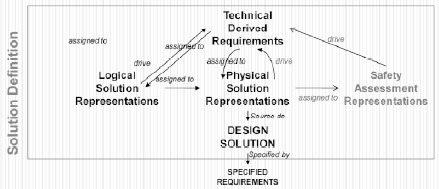
We have introduced the derivation mechanism enabling the replacement, in the design process, of a system level PBR by the conjunction of derived requirements (PBRs) assigned to all or a part of its subsystems in section 7.2.
For such a derivation Rq →[Rq1,..,Rqn} to be true, the following formal relationship shall be established:
[10.1] ![]()
This relationship [10.1] means that the conjunction of derived requirements Rqi assigned to subsystems sΣ1,…, sΣn of a system Σ shall be more constraining than the system requirement Rq it is derived from, if the design choices (DCs) are respected.
The derivation of a safety requirement Rq assigned to a type of systems Σ complies with this general mechanism and produces a set of derived safety requirements Rqi assigned to all or a part of its subsystems (sΣ1,…, sΣn). This derivation essentially depends on the structure of Σ, that is to say its architecture. Any change in the structure usually makes the derivations depending on it obsolete.
For system safety considerations, we are often brought to consider typical structures (patterns) on which the analyses are based, because they enable assessments based on different probability calculi theorems or technological operative rules, and on which we can base ourselves to derive quantitative and qualitative safety requirements.
Table 10.5 shows some of the most famous design patterns; many other patterns can be considered such as the “stand-by redundant systems”, “load sharing systems” and “non- parallel-series systems” patterns (see [VIL 88] or [MOD 10]).
Table 10.5. Examples of system design patterns considered for safety aspects
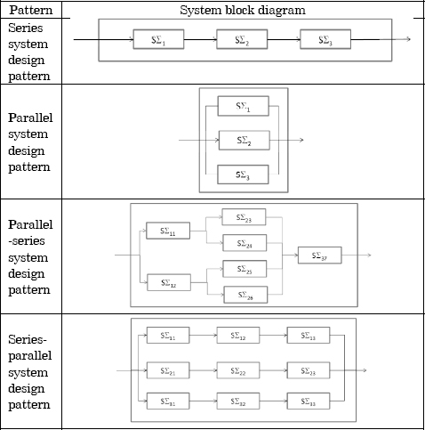
If we consider the following quantitative safety requirements:
RqΣ: val(Σ.failure_rate) ≤ ∧Σ
Rq s Σi: val(s Σi. failure_rate) ≤ λsΣi
Then, the derivations for the patterns above (Table 10.5) are true:
when SeriesSystem → RqΣ ≤ RqsΣ1 ∧ RqsΣ2 ∧ RqsΣ3 iff ∧Σ ≤λsΣ1 + λsΣ2+ λsΣ3 (1)
when ParallelSystem → RqΣ ≤ RqsΣ1 ∧ RqsΣ2 ∧ RqsΣ3 iff ∧Σ ≤max(λsΣ1, λsΣ2, λsΣ3)(2)
when Parallel-SeriesSystem →RqΣ ≤ RqsΣ11 ∧ .. ∧ RqsΣ7 iff ∧Σ ≤ max(ΣsΣ11, ΣsΣ12) + max (max (λsΣ11, λsΣ12), max(λsΣ11, λsΣ12))+λsΣ7 (3)
when Series-ParallelSystem → RqΣ ≤ RqsΣ11 ∧ .. ∧ RqsΣ33
iff ∧Σ ≤ max(λsΣ11+λsΣ12+λsΣ13, λsΣ21+λsΣ22+λsΣ23, λsΣ31+λsΣ32+λsΣ33) (4)
In the same way, if we consider the following qualitative safety requirements:
RqΣ: val(Σ.DAL)=X with X ∈{A, B, C, D, E}
Rq sΣi: val(sΣi.DALi) ≤ xi with xi ∈{A, B, C, D, E}
The following derivations, which are an interpretation of Table 3 of the ARP4754A, for the patterns SeriesSystem and ParallelSystem are true:
when SeriesSystem → RqΣ ≤ RqsΣ1 ∧ RqsΣ2 ∧ RqsΣ3 iff ∀i, xi =X (1)
when ParallelSystem → RqΣ ≤ RqsΣ1 ∧ RqsΣ2 ∧ RqsΣ3 iff {∃i xi=X, ∃j≠i, xj=succ(succ(X))} or {∃i, j j≠i, xi= xj=succ(X),}
10.3.4. Simulation and validation of the derived safety requirements
The process of validation by simulation of derived requirements described in section 8.3.4 is entirely applicable to the derivation of quantitative and qualitative safety requirements, such as we defined them above.
The goal of this validation is to ensure the correctness of these derivations and their completeness. It will ensure the satisfaction of the system level safety requirements for a given structure of the system, if the derived safety requirements are satisfied.
The levels of rigor mentioned in section 8.3.5 are applicable. We will note that the determination of the effect resulting from the components’ structural properties on the corresponding system level structural properties, requires the introduction, within the structural design model, of virtual components, able to compute these effects.
We define these components as virtual, in the sense that they correspond to no real, tangible, objects, but are the models (approximately true) of the, no less real, laws of physics.
This is particularly the case for the assessment of failure rates per flight hour of a type of systems, which depends, on the one hand, on the failure rate per flight hour of each of its components and, on the other hand, of the system architecture, as illustrated for a system in sequence in Figure 10.8.
In this first structural design model, the virtual component “failure rate” encapsulates the statistical law linking the failure rate of a system in series to that of its physical components.
Figure 10.8. SDM virtual component computing failure rates
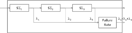
Figure 10.9. SDM virtual component computing DAL
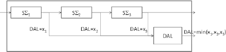
This is also the case for the assessment of the FDAL of a type system, which depends, on the one hand, on the F/IDAL of each of its components and, on the other hand, on the system architecture, as illustrated for a system in sequence in Figure 10.9.
For this example, the structural design model embeds the virtual component “DAL”, encapsulating the technological operative rule fixing the FDAL of a system in series as a function of the physical components F/IDAL.
As we can imagine, these virtual components can be used to determine the system level resultant of many structural properties, such as mass balance, inertia balance and electric consumption balance. Often, they are linked to the structure of the type of systems under consideration. A noteworthy exception concerns the mass balance, which is independent of the type of systems structure, and only depends on the constitutive components.
10.3.5. Simulation and verification of the failure prevention mechanisms
The verification process by simulation of the design models with regard to the specification model described in Chapter 9 (section 9.3) is entirely applicable to the verification of the design with regard to the quantitative and qualitative safety requirements, such as we described them above.
The goal of this verification is to ensure the safety properties (effective F/IDAL or effective failure rates) of the components such that they go back up the development and assessment “bottom-up” processes, satisfy the component level safety requirements and enable the integrated system to satisfy its own requirements (FDAL or failure rate).
They also enable us to verify by simulation, with the required level of rigor, that the mechanisms introduced at the system structural level to prevent or mitigate failures being efficient, that is to say the mechanisms enable the system to tolerate single or combined faults, while ensuring the required function without failure.
They finally enable us to verify by simulation, with the required level of rigor, that the reconfiguration mechanisms designed to passivate the faults and ensure the function to be carried out are maintained, and respond effectively.
There are several safety mechanisms being considered, and they notably include redundancies, segregations, dissimilarities, feedback loops, voting and reconfiguration mechanisms.
This kind of verification requires setting up the last type of design models manipulated in the Property Model Methodology (PMM), which we present in the following section, namely the reliability design models (RDMs) inspired from the reliability block diagrams (see [VIL 88] or [MOD 10]) used, instead of (or complementarily to) the failure trees method.
10.3.6. Reliability design models
RDMs are models designed to verify the robustness of a system regarding internal faults.
We can, according to the needs, consider single fault or even combined faults to measure their effects (failures), verify the intended effectiveness of the fault passivation and reconfiguration mechanisms. They can also enable the detection of common fault modes linked to the considered architecture of the type of systems under consideration.
Figure 10.10. Reliability design model b) derived from a baro-altimeter structural design model a). For a color version of this figure, see www.iste.co.uk/micouin/MBSE.zip
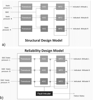
An RDM model, in Figure 10.4(b), derives directly from a structural design model (a). The analysis of this structural design model enables the systematic identification of internal faults of the type of system under consideration. These faults manifest at each component output. Thus, in Figure 10.4(a) a “transducer”, an “ADC” or an “MFD” can lose its output flow, or even produce an undetected faulty output flow. This example highlights 18 single faults.
An additional virtual component, the “Fault Intruder” enables the intrusion of simple or combined faults by corrupting the outputs, according to the needs and objectives assigned to the RDM. Thus, in the example, during the execution of a simulation scenario designed to verify the tolerance of an architecture to single faults, the “Fault Intruder” can inject one of the 18 single faults identified, which will successively corrupt the different outputs from different components constituting the system. In this way, we can ensure the ability of the system structure to tolerate single faults.
Although no general common cause fault detection mechanism exists, the RDMs can enable, on the one hand, the detection of those linked to the structure while, on the other hand, model configuration mechanisms can cover dissimilarity requirements between components through an assessment of the configuration indexes.
10.3.7. Safety theorem: validating additional requirements
We conclude this chapter with a specific point, related to the introduction of additional requirements at the subsystem specification model level, and its impact on the safety of the type of systems that includes such a subsystem.
A rule of the art dictates that the global impact on the safety of the encompassing system shall be evaluated when some additional requirements are introduced at the subsystem level. This assessment is necessary when working with textual specifications, particularly when the system specification has weaknesses, which are compensated by additional subsystem requirements.
However, we will show that this assessment becomes superfluous so long as the PMM and PBRs are used.
This is the safety theorem: the introduction of any additional PBR at the component level of a type of systems has no effect on the safety of that type of systems.
To demonstrate this theorem, we consider a feasible type (that is to say non-empty) Σ of systems, specified by a set of PBRs {PBR1, .., PBRn}. We have Σ=SAT({PBR1, .., PBRn})≠ ∅. We now suppose that these systems present a failure F. We characterize this failure in the following way: when a condition C is satisfied, a property P is in a domain D, considered as unacceptable (for example, because its consequences would be catastrophic), in other words, the faulty state is constituted of the conjunction of the condition C and the fact P is in D (F=C∧ (P∈D)). To prevent this failure, we introduce the safety requirement:
PBRsafety : when C => P∉D
It then follows that the systems of type Σ, which satisfy this PBRsafety requirement, define a subset Σ′ of Σ such that Σ′ = SAT({PBR1, .., PBRn, PBRsafety}).
If the systems of the subset Σ′ are feasible (Σ′≠∉), then they are protected against the failure F.
We now suppose that Σ′ is composed of (DC) the subsystems O1, .., Op. Then, each PBRi of {PBR1, .., PBRn, PBRsafety} applied to Σ′ has been derived into PBRij or PBRsafetyj applied to all or a part of the components O1, .., Op , according to DC.
If all the derivations of PBR requirements are true (valid), then the conjunction of requirements assigned to Σ′ is less constraining than the conjunction of all the requirements assigned to the different components of Σ′, that is to say:
when DC => PBR1 ∧ .. ∧ PBRi ∧ .. ∧ PBRn ∧PBRsafety
≤(PBR11 ∧ .. ∧ PBR1j ∧ .. ∧ PBR1p∧PBRsafety1)
(PBRi1 ∧ .. ∧ PBRij ∧ .. ∧ PBRip∧PBRsafetyj)
..
(PBRn1 ∧ .. ∧ PBRnj ∧ .. ∧ PBRnp∧PBRsafetyp)
The result of this is therefore that a system, with an architecture compliant to DC and where each component Oi is compliant with the requirements {PBRi1, PBRij, PBRip,PBRsafetyj}, is protected against failure F.
If, finally, a PBRadd requirement is added to the specification of component Oi, for any reason, we will still have:
(PBRi1 ∧ .. ∧ PBRij ∧ .. ∧PBRip∧ PBRsafetyj) ≤ PBRi1 ∧ .. ∧ PBRij ∧ .. ∧PBRip∧ PBRsafetyj) ∧ PBRadd
and the relationship remains true.
when DC => PBR1 ∧ .. ∧ PBRi ∧ .. ∧ PBRn ∧PBRsafety
≤(PBR11 ∧ .. ∧ PBR1j ∧ .. ∧ PBR1p∧PBRsafety1)
(PBRi1 ∧ .. ∧ PBRij ∧ .. ∧ PBRip∧PBRsafetyj) ∧ PBRadd
..
(PBRn1 ∧ .. ∧ PBRnj ∧ .. ∧ PBRnp∧PBRsafetyp)
In other words, a system with an architecture compliant with DC and where each component Oi is compliant with the requirements {PBRi1, PBRij, PBRip,PBRsafetyj} and to which we have added additional requirements remains protected against failure F.
NOTE.- If the introduction of any additional PBR at the component level of a type of systems has no effect on the safety of that type of systems, it remains true that this introduction has an effect on its feasibility. Indeed, the introduction of a new PBR always has an effect of reducing:
which converge to the empty set ∅, that is to say toward the non-feasibility, if we do not pay attention to it.
10.4. Conclusion
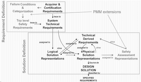
As we have seen it previously, the PMM is a strongly integrated approach of development processes (specification and design), requirements validation, design verification and safety assessment processes.
This brings us to propose an extension of the EIA 632 design process by adding to it, and at different levels such as the requirement definition process and solution definition process, activities related to safety assessment.
In Figure 10.11, on the one hand, a safety requirement determination activity is integrated in the EIA 632 requirement definition process, and on the other hand, an activity defining the safety assessment representation, the RDMs from which it is possible to carry out safety requirement validation activities and activities verifying the design model in relation to the safety requirements, integrated in the EIA 632 solution definition process.
Figure 10.11. Extended EIA 632 design process model. For a color version of this figure, see www.iste.co.uk/micouin/MBSE.zip
1As an example, Regulation (EC) No 216/2008 of the European Parliament and of the Council of 20 February 2008 on common rules in the field of civil aviation and establishing a European Aviation Safety Agency, and repealing Council Directive 91/670/EEC, Regulation (EC) No 1592/2002 and Directive and repealing Council Directive 91/670/EEC.
2“Aeronautical product” means any aircraft, aircraft engine, aircraft propeller or aircraft appliance or part or the component parts of any of those things, including any computer system and software.
3A safety requirement is a quantitative requirement if the compliance demonstration requires numerical analytical methods (AMC25.1309, p. 2-F-41); otherwise, it is qualitative.
4“No single failure will result in a catastrophic failure condition AC29-2C page F-18”.
5Federal Aviation Administration, Advisory Circular AC25-11A, Electronic Flight Deck Displays, 6-21-2007.
6AC29.1309 in Federal Aviation Administration, Advisory Circular AC29-2C Change 3, Certification of Transport Category Rotorcraft, p. F-12, 30 September 2008.