
Chapter 15
LEGO Direct
In This Chapter
![]() Adding a reset button to your Raspberry Pi
Adding a reset button to your Raspberry Pi
![]() Saving on batteries for your EV3 brick
Saving on batteries for your EV3 brick
![]() Controlling the LEGO motor directly from your Raspberry Pi
Controlling the LEGO motor directly from your Raspberry Pi
![]() Reading the motor’s rotary sensors
Reading the motor’s rotary sensors
![]() Revealing the secrets of the EV3’s sensors
Revealing the secrets of the EV3’s sensors
![]() Accessing the LEGO peripherals without building anything
Accessing the LEGO peripherals without building anything
In the previous two chapters, we show you ways to communicate with the LEGO MINDSTORMS EV3 Intelligent Brick. In this chapter, we get a lot more hacky and look at controlling motors and reading sensors directly from the Raspberry Pi.
You can make your own cables that are much more flexible than the official cables, and we show you how in this chapter. Finally, when using the Raspberry Pi with a LEGO system, you can save on battery power and customize your project to your liking, and we cover all that in the pages that follow.
Creating a Reset Button for the Raspberry Pi
A reset button on the Raspberry Pi may not seem obvious, and we never needed one until we started playing around with Bluetooth, but it’s a great idea for when everything is stuck. (Sure, you can just yank out the power lead, but that isn’t really recommended because it could cause trouble with your SD card.) Even though there is no reset button on the Raspberry Pi, provision has been made for fitting one from revision 2 of the board. You can see it in the form of two holes to the left of the HDMI socket — it’s very easy to solder a two-pin header there. The idea is that when these two lines are shorted together, the Raspberry Pi’s processor is reset.
You can use a jumper link to temporarily connect these two lines together when needed, keeping the jumper on one pin for normal operation. However, you can go for the deluxe method and wrap a tact push button’s wires around a two-pin header to produce an actual button. As an alternative, you can solder a button directly into the two holes. Make sure you have a two-wire push button because there are many four-wire ones out there. Figure 15-1 shows some photographs of this. On the right is a tact push button wired to a two-pin socket; on the left, it’s mounted on a two-pin header soldered into the Raspberry Pi’s board.
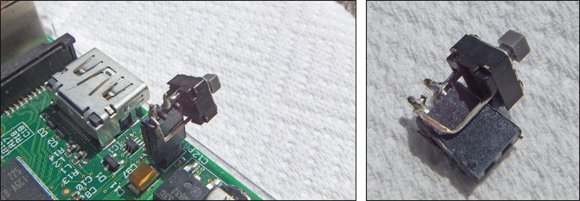
Figure 15-1: Raspberry Pi reset buttons.
Making Batteries Last Longer
Having done a few projects using the LEGO EV3 system, we noticed that the batteries didn’t last very long. In fact, during development, the brick would often sit there doing nothing for long periods while we concentrated on the Raspberry Pi aspect of the software. Turning the brick on and off takes some time — about 30 seconds to power up and 45 seconds to power down — so you tend not to do it too often. Although there are rechargeable batteries for mobile use, static LEGO machines like the dice game in Chapter 14 can get away with a tethered power supply.
The LEGO system runs off 6 AA batteries; at 1.5V each, that adds up to 9V. All the solutions we found to this problem online involved some very ugly soldering of wires directly onto the battery springs. We thought that this was a bit too intrusive. Plus, it was difficult to swap between a power supply and batteries. So, we wanted something that would look like a AA battery and allow us to connect wires to it. While thinking, “What is about the size of a AA battery?,” we came up with the answer: “A AA battery!”
The battery cover at the bottom of the EV3 brick has a small flange that covers a U-shaped hole in the body of the brick. This hole is just about long enough to put a long-reach 2.1mm power jack through, so all we had to do was to attach a matching socket into something that was the same length as a AA battery. However, it isn’t quite as easy as that because the spring that holds the battery in place tends to apply a snapping force to the center of any tube. After a few false starts, we hit upon the solution, shown in Figure 15-2.
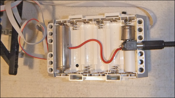
Figure 15-2: The LEGO brick battery eliminator.
All this system has to do is to connect the positive end of your external power supply to the top-right spring in the battery compartment and the negative end to the top-left spring. The basic idea is that a surface-mount power-jack socket lines up with the center notch in the battery compartment and attaches to the negative connector of the brick. It’s held in place by a styrene tube, which fits around the narrow pip on the battery holder’s spring positive connector. This pip is what causes trouble — it’s too narrow to allow a stable fitting. The tube and the left-hand side of the PCB fit around the pip, preventing it from producing any sideways movement and holding the assembly stable. The positive connection from the jack socket is wired to the full battery’s body with a wire soldered to the body. Note the positive connection is the main body of the battery with the negative connection just the end.
To make this project, you need the following parts:
- Two old dead AA batteries (the plastic-covered type, not the painted type)
- A surface-mount 2.1mm power-jack socket
- A 7mm x 30mm piece of single-sided PCB material
- A styrene tube with an outside diameter of 20mm x 11mm
- 70mm of 24-gauge (or thicker) insulated wire
- A long-reach 2.1mm power-jack plug
- A small amount of epoxy resin
- A 9V regulated mains power supply (an SPS-8041 or similar)
To build the battery eliminator, follow these steps:
- Take the two batteries and strip off all the plastic covers, leaving just the bare metal.
Using a small hacksaw, gently saw off the last 16mm of the negative end of one of the batteries.
Make sure you catch the black stuff that comes out in a paper towel. You’ll find that you’ve also sawed through a rod that runs down the center of the battery.
 The black stuff is a compressed paste of manganese dioxide with carbon powder added for increased conductivity. The sticky stuff surrounding the center negative electrode is composed of zinc powder in a gel containing the potassium hydroxide electrolyte wrapped up in a layer of cellulose or a synthetic polymer.
Remove all the black stuff, leaving just the center electrode.
We did this by putting a small screwdriver in and scratching the black stuff out. It comes out very easily.
 Make sure you catch all the black stuff and don’t get it in your mouth. Don’t dispose of this in the normal household garbage; instead, place it in a resealable plastic bag and put it with your other dead batteries for proper disposal.
- Bend down the central electrode rod until it nearly touches the case.
- Slip the piece of PCB material into the tube and push it as far in as it will go.
- Solder the electrode rod to the PCB material.
- Take a small amount of epoxy resin and fix the PCB into the battery case. Let it set for 24 hours.
- Make sure the surface mount socket lines up with the center of the hole in the LEGO brick when the battery retaining spring is compressed about halfway. Then solder the surface mount socket in place on both sides.
Solder an insulated wire from the center pin of this socket to the body of the other whole battery.
 Clean up the area first with glass paper and make the joint quickly with a soldering iron. Don’t allow the battery to heat up too much, and allow it much longer than usual to cool down. The bulk of the battery means it will absorb more heat before you can solder it.
Cut 20mm of styrene tube and fit it over the PCB material. Then place it in the battery holder.
The construction is shown in Figure 15-3. A photograph is shown in Figure 15-4.
Wire up a long 2.1mm power jack with the center pin as the positive and attach it to your 9V power supply.
We used an SPS-8041 selectable switch mode supply set to 9V for this. You may want to cut off the small flange in the battery cover that covers up the hole for the power jack, or you may want to leave your LEGO unmodified and just operate the brick with no back cover. The choice is yours.

Figure 15-3: The construction of the battery clip.
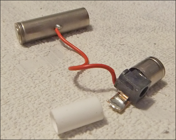
Figure 15-4: The battery clip.
Now you can happily power your EV3 brick during development and quickly change to batteries when needed.
Using Connectors and Cables to Control the LEGO Motors and Sensors
If you want to have direct control of the LEGO motors and sensors, you have to get electrical access to them. All the electronic components in the EV3 and NXT systems are connected to the control brick using a six-way connector called an RJ12. The RJ12 is very similar to the RJ11 connector — the only difference is that the RJ11 uses only four of the six wiring positions of an RJ12. Sometimes an RJ12 connector is called a 6P6C RJ11; this stands for six positions and six connectors (whereas the normal RJ11 is a 6P4C connection).
Although these are both standard connectors in the electronics industry, the LEGO designers added a small tweak to make things a bit difficult (or as LEGO would probable say, to ensure the MINDSTORMS system was not connected to things it should not be connected to). The RJ11 and RJ12 connectors have a latch on the top to allow for the cable to be locked into the socket. Normal connectors have this connector in the center, but the LEGO system has it offset on the right side. There was an old RJ11 telephone connector with an offset latch, but that was offset on the other side, so making extra cables isn’t straightforward.
RJ12 cables are normally crimped onto the connectors. You get a special size-6 core flat cable and strip off the outer insulation. Then you put the insulated wire ends into a plug and crimp it with a special tool. This does two things:
- It distorts a plastic bar to push against the wires and acts as a mechanical clamp.
- It pushes the blades on the back of the plug’s contacts through the plastic of the wire’s insulation to make a contact.
Done properly, this produces a good durable connection. The only snag is that the double insulation tends to make the resulting cables a bit stiff, which can sometimes cause problems when connecting parts that move.
There are several things you can do with the leads to improve them or allow electrical access to the signals, some of them more straightforward than others:
- Hack an existing lead. This approach is perhaps the simplest one to take. You have a lead with two ends, so you can simply cut it in half, and you have two ends to solder your extension wires onto. If you want to extend the cable to use more flexible wires, you can cut the cable close to the connector and insert a length of stranded wires with thinner insulation. Make sure you cover any exposed joints with insulating tape or, better yet, a dab of liquid insulation tape.
- Use a normal RJ12 and crimp tool, but move the latch over to the right side. We’ve seen this method advocated on some websites, but we haven’t had much success with this technique ourselves. The idea is that, after you’ve fitted the cable, you slice off the tab with a sharp knife and glue it on the side using polystyrene model airplane glue, using an existing socket as a guide so you get it in the right place. You have to be very careful not to permanently glue the cable into the socket; plus, the springiness of the latch is in question after the gluing.
Get some real connectors. In our opinion, the best approach is to get some real connectors, ones designed for the job. Unfortunately, there isn’t a great deal of choice with suppliers — we could only find one source, but they’re available on both sides of the Atlantic. In the United States, go to
www.mindsensors.com; in Europe, go towww.active-robots.com. Here, you can buy sockets and readymade leads, as well as the plug connectors.However, if you’re going to make your own lead, you need a crimping tool, and the only way we know of accommodating the offset latch is to modify an existing crimping tool. Crimping tools can be quite expensive, but if you choose the right one, it’s not only cheap but also easy to modify.
The LogiLink crimp tool is inexpensive and made from bright orange plastic, so it’s simple to modify. It crimps four-position, six-position, and eight-position connectors. The two halves unscrew, and it’s comparatively easy to file a larger slot in the six-position hole to accommodate the offset latch. We used a small square needle file to do this. Figure 15-5 shows the slot filed away on the front piece. Note that you also need to file the back piece. You have a connector of the right size in the LEGO set, so it’s easy to file the crimper so that the plug fits in snugly.
We found that the best wire to use was ribbon cable. The vast majority of ribbon cable is 0.1-inch pitch, but it’s too big for these connectors so what you want is 1mm pitch cable. All you need to do is cut the cable off square, insert it into the socket, insert the socket in the crimper, and squeeze. For a bit of added resilience, we added a small spot of Gorilla Glue to the cable underneath the clamping bar. We left this a few hours to set before flexing the cable.
Using this method, you can make flexible two-ended cables of exactly the right length for your model. Or you can make single-ended cables for attaching your LEGO parts to other electronics or your Raspberry Pi.
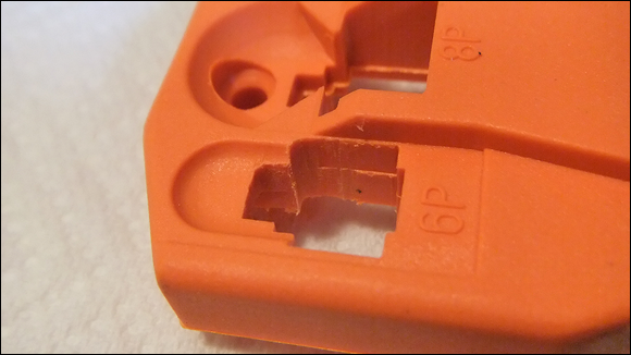
Figure 15-5: Crimp tool modification.
Reading and Commanding
There are basically two different sets of signals you can get on the LEGO control brick:
- Sensors: You read information from these. They’re labeled A through D.
- Actuators or motors: You command these to move. They’re labeled 1 through 4.
Each has a different set of electrical connections. Figure 15-6 shows the signals on the two types of LEGO peripherals. Note that this is oriented with the latch on the underside. The colors used on a standard LEGO cable for each wire are also shown in Figure 15-6.

Figure 15-6: LEGO cable signals.
The motor lead
The LEGO motor basically consists of two components:
- A geared motor capable of clockwise or counterclockwise rotation
- A rotary sensor giving pulses in response to the motor movement
The motor is geared, through a multigear train, so it turns many times before the movement is transmitted to the outside world.
To get a motor to move, you apply a voltage across the Motor Power 1 and 2 lines. This should be 9V, but the voltage isn’t too critical. To make it reverse direction, you need to swap the polarity of these two lines. To stop the motor, you can do one of two things:
- Remove the power by removing the voltage from these lines. When you do this, the motor will coast to a stop.
Make the two power lines be the same voltage — either both 0V or both 9V. This is not the same as disconnecting the voltage. Instead, it’s like connecting the two motor wires together. This results in the motor stopping very quickly by means of what is known as regenerative breaking or flywheel breaking.
Flywheel breaking works because an electric motor that is turning is actually acting like a generator and is producing a voltage that is in the opposite direction of the voltage required to make the motor turn in that direction. So, by connecting the two wires of the motor, you’re using the voltage generated by the movement of the motor to try to drive the motor backward. This is like a power shutdown and stops the motor much faster than just letting it coast to a stop.
You may have noticed the two stop modes in the LEGO language — the break at end can be true or false. This is a simple way of saying “stop by coasting” or “stop by flywheel breaking.”
The other control the motor has in the LEGO language is the power. (This used to be called speed, but power is a more accurate description.) You can reduce the power sent to a motor and, thus, see a speed drop by very rapidly turning the motor on and off. This happens hundreds of times a second. By changing the relative time the motor is on and off (known as the duty cycle), you can reduce the power fed into the motor.
For example, at 500 times a second, the motor is turned on and off every 0.002 second or 2 milliseconds (mS). If the motor is on for 1 mS and off for 1 mS, the power will only be 50 percent of full power. This rapid switching of the motor and changing the duty cycle is known as pulse width modulation (PWM) and is a common way of backing off the power on motors. Depending on the mechanical load the motor is under, the speed will also drop. The off part of the cycle is normally a flywheel breaking type rather than coasting type.
The last part of the motor is the rotary sensors, which give feedback on the actual movement of the motor. Applying power to the motor is great, but it may be jammed up or one motor may actually spin faster than another even if they’re given the same voltage. Each motor is fitted with a rotational sensor. The sensor works similarly to a mouse with a ball: Any movement rotates a disc with holes that block and unblock one of two infrared beams. These beams produce pulses that can be related to the motor’s actual movement.
The beams are quite accurate — you get one pulse for every degree of rotation. In fact, there are two pulse outputs that are 90 degrees out of phase with each other (known as a quadrature arrangement). By looking at which pulse line changes first, you can also determine the direction of rotation. These pulses on their own can be used to find how much a motor has moved, even if it isn’t powered and is moved only by hand. However, the pulses can’t be used to find the absolute position of the motor — only the relative motion or how much it has moved.
The sensor lead
The sensor leads, connecting to the sensor ports A through D, carry a very different sort of signal. Pin 3 is ground and pin 4 is positive, and they carry the power supply for the sensor. The new EV3 sensors communicate using the serial RS485 protocol at normal TTL logic levels. Communication between brick and sensor can be complex, as you see later in this chapter.
Rolling Your Own Motor Control
In order to control LEGO motors directly from the Raspberry Pi, you have to convert the signals available on the Pi’s general-purpose input/output (GPIO) pins into signals suitable for driving the motor. The GPIO pins, when used as outputs, can provide only a very small current (16 mA at 3.3V). The LEGO motor needs a voltage of 9V at a current of 60 mA when under no load, and up to 2,000 mA when it’s stalled. In order to make the motor turn in either direction, any driving circuit needs to be able to swap the polarity of the voltage on the motor’s wires. In order to get regenerative breaking, a circuit needs to be able to connect the two wires from the motor together. A circuit that can do this is called an H-bridge circuit; it’s composed of two half H-bridges.
A half H-bridge is simply what you get with a changeover switch (a switch that can be connected to either one of two poles or positions). With each pole connected to the two polarities of the motor’s power supply, you can make an H-bridge (as shown in Figure 15-7) using only switches.

Figure 15-7: An H-bridge made from switches.
The common connector of each switch is connection to one wire of the motor, as you can see in Figure 15-7a — one switch is up and the other is down, so the current flows through the motor and causes the motor to turn in a clockwise direction. If the two switches are reversed, so switch 1 is down and switch 2 is up, the current flows through the motor in the opposite direction and the motor rotates in the opposite direction, as shown in Figure 15-7b. Finally, in Figure 15-7c, both switches are down and the two motor wires are connected together allowing regenerative breaking to occur. Note that this would also happen if both switches were up; if they’re both connected to the same voltage level, they’re in effect connected together.
Making it move
The only problem with an H-bridge made from switches is that you would have to physically switch them. You could use relays to make the contacts, but there is a pure electronic method that does not involve any moving parts. Fortunately, this is such a common circuit that many integrated circuits are available with this configuration, so you don’t need to make one from individual parts.
If you just want to control the direction of the motor, all you need is an H-bridge circuit. But if you want to control the power/speed of the motor, you need to apply some PWM to the voltage. Unfortunately, the Raspberry Pi is not very well endowed with PWM signals — there are just two on the processor, and you can only get to both of them on the plus model’s GPIO pins; the earlier models could access only one. These pins are also used for generating sound so if you’re controlling a motor, the Raspberry Pi can’t make any sound. Although each motor can have its own PWM control, with a Raspberry Pi 2, there is a sneaky trick that will work with all models to control two motors with one PWM pin. The way this works is to use logic gates to pass or block signals to the H-bridge switches. The gates we’ve chosen to use are called NAND gates (which stands for Not AND), and they’re among the most common gates.
Logic gates have rules for what their output will be when presented with all the possible different combinations of inputs. In words, an AND gate will have a true output when input A and input B are true. A NOT gate has an output that is not the input, so if the input is true, the output is false, and if the input is false, the output is true. A NAND gate is an AND gate followed by a NOT gate.
All this gets very wordy, and you can quickly become muddled, so it’s normal to have a table that shows every possible combination of inputs and the output results. This is known as a truth table; three such tables are shown in Figure 15-8.

Figure 15-8: Logic truth tables.
The AND gate has two inputs — A and B — so there are four different possible combinations, each with its own row in the table. The symbol for an AND gate is shown below the table. Similarly, because the NOT function has only one input, there are only two lines. Sometimes this function is called a logic inverter or just an inverter for short. Finally, a NAND gate simply has the output of the AND gate inverted. Notice how the symbol for the NAND gate takes the filled circle from the output of the inverter and combines it with the body of the AND gate symbol.
Perhaps one of the more mind-boggling aspects of digital logic is that, when you have a NAND gate, everything else can be made up from this one function. That means that circuits that add up numbers, circuits that count, circuits that remember … all the circuitry of your microprocessor or any computer can be made up of NAND gates. No other functions are necessary. However, showing you how this can happen would take up a whole other book.
So, why do you need to know about NAND gates here? Well, we use them to send PWM signals or not send them into the H-bridge inputs to control the motor. Figure 15-9 shows the motor-activating part of an interface circuit for the Raspberry Pi to control a LEGO motor. With this circuit, you can control two motors. This circuit can also be used to control any sort of low-power DC motor.

Figure 15-9: A motor-activating interface.
The circuit consists of two interface circuits: the H-bridge and the NAND gate. In fact, the 74HC00 contains four NAND gates, and the SN754410 contains two H-bridge circuits (or, to be more accurate, it contains four [or quad] half H-bridge circuits). There are two supply voltages for this chip: One is for controlling the logic signals, and the other is for driving the motor. The motor supply can be anything up to 36V, but for a LEGO motor you should stick to between 9V and 12V. The negative of the motor’s supply must be connected to the ground connection of this circuit.
The enable lines of the two H-bridges are connected to the logic supply so that they’re always on. You can apply the PWM to these lines, but then power control is less effective because the motor will coast through the off parts of the cycle. If you want, you can connect these enable lines to another Raspberry Pi pin to shut down the motors altogether, but there isn’t much reason for this because the other pins will allow you full control of the motor.
Each of the two control lines for the motor passes through an NAND gate, which has the effect of “gating” the PWM signal. When the PWM signal is low, both control lines to the H-bridge are high, so the motor is in the breaking mode irrespective of what state either of the control lines is in. However, when one control line is high, and the other is low, the rapid PWM signal is applied to the H-bridge control input corresponding to the high motor control, with the other H-bridge input being permanently high. This is exactly what you need for power control, as well as directional control.
This circuit can drive the LEGO motors in the LEGO Technics and the LEGO Power series, as well as the original MINDSTORMS motors. However, the NXT and EV3 motors have another trick up their sleeves: built-in rotational feedback.
Note how the motor’s voltage is shown as 9V to 12V. The LEGO motor is capable of being run at 12V. But even so, the H-bridge circuit can cut the applied voltage down by as much as 3V, so even supplying the bridge with 12V, the motor gets only a touch over 9V anyway. So, if you supply the drive circuit with 12V, it will act like a very fresh battery; if you supply it with 9V, it will act like a partly discharged battery.
Knowing where it is: Motor feedback
The built-in sensor is known as an quadrature incremental rotary encoder, and produces pulses, as shown in Figure 15-10. These signals are 90 degrees out of phase from each other. By looking at the relative positions of the edges, you can determine the direction of rotation.

Figure 15-10: Rotary encoder outputs.
The sequence of levels you get from the sensor as it’s rotated is also shown in Figure 15-10. Notice how, as the rotation proceeds, only one bit will change at a time. This property in a code makes the code what is known as a Gray code, named after its inventor, Frank Gray. To a certain extent, it’s self-correcting against contact bounce by having some forbidden transitions. If you see one of these transitions, you know it’s an error and it’s a simple matter to ignore in software.
To condition these signals into a form suitable for input to the Raspberry Pi’s GPIO pins, a comparator or Schmitt trigger circuit is normally used. The LM339 has four comparators in one package and also has an open collector output, which means it can be simply pulled up to the 3V3 logic supply of the Raspberry Pi with a resistor. The schematic of this buffer circuit is shown in Figure 15-11.

Figure 15-11: The motor sensor interface.
This circuit can handle the rotation outputs for two motors. Each output is connected through a 10K resistor to the positive comparator input to provide some protection against interference pickup. All the comparator’s negative inputs are connected together and set to a voltage that is halfway between the two extremes of the signal. The sensor circuit in the motor is powered by not 5V but 4.3V. We’re sure it would work fine with 5V, but it’s easy enough to provide the correct voltage by simply passing it through a diode. Any rectifying diode will do fine.
Constructing the motor control system
Building both aspects of the motor control system on one circuit board is best, so we’ve have combined the two schematics (Figures 15-9 and 15-11). Here are the parts you need:
- Four 10K resistors (R1–R4)
- Five 3K3 resistors (R5–R9)
- One 4K7 resistor (R10)
- Four 0.1uF ceramic capacitors (C1–C4)
- A 1N4001 or similar rectifying diode (D1)
- A 74HC00 quad two-input NAND gate (IC1)
- An SN754410 quad half H-bridge (IC2)
- An LM399 quad comparator (IC3)
- Two RJ12 six-way sockets with offset latches (S1–S2)
- Stripboard
- Connecting wire
- Two 14-pin DIL IC sockets (optional)
- A 16-pin DIL IC socket (optional)
- A 12-way screw terminal strip, 0.2-inch pitch
- A 4-way screw terminal strip, 0.1-inch pitch
The last two items can be combined as a 16-way 0.2-inch screw terminal strip at the expense of having a larger stripboard.
The only component you may have trouble getting ahold of is the RJ12 socket; you can get them from the same supplier you get the RJ12 plugs from. You can dispense with them altogether if you cut a cable in half and solder the wires directly onto the stripboard. If you do get a socket, you have the problem of mounting it on the stripboard. The trouble is that the socket is not on a 0.1-inch grid, so there is a bit of work to mount it. Just follow these steps:
Drill two 2.5mm mounting holes for the fixing lugs four and a half holes apart.
Drilling the half-space hole can be tricky.
- Run two rows of three holes together by putting a small router bit in your drill.
- Remove the copper between the two slots with a scalpel.
- Before you push the socket into the board, smear a small spot of Gorilla Glue to the base of each socket in order to provide a good mechanical joint.
Wrap thin wire around the protruding socket connectors.
The pin out of this socket as viewed from the underside is shown in Figure 15-9. A photograph of the slots we cut in the stripboard are shown in Figure 15-12.
Figure 15-12: Stripboard preparation for mounting the RJ12 socket.
The wires connecting this board to the Raspberry Pi’s GPIO pins are connected on our board through screw connectors. In order to fit them onto the board size we chose, we used two sizes of screw connectors, but for economy you can eliminate these altogether and solder wires directly to the stripboard.
A photograph of our board is shown in Figure 15-13. There is little point showing the wiring because the stripboard isn’t used to make any connections — it’s all wired up on the underside of the board.
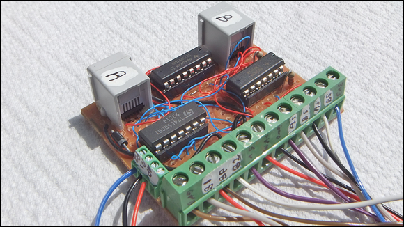
Figure 15-13: The motor interface board.
Writing the software
Having built the interface board, you need some software to run it. This software needs to have access to the GPIO pins. There are a few libraries to choose from, but we chose WiringPi2 for Python. This is a port of Gordon Henderson’s C library. It uses a syntax that will be familiar to any Arduino user. If you aren’t an Arduino user, it takes just as much learning as any other library syntax.
So, the first thing to do is install it. From a command line, type the following:
sudo apt-get updatesudo apt-get install python-dev python-pip
When that has finished, type the following:
sudo pip install wiringpi2
That’s it. However, Linux now throws you a curveball in that you have to run as root before it will allow you access to the GPIO pins. If you use IDLE to do your Python development, you can run this as root. From the desktop, open a command window and type the following:
gksudo idle
The IDLE package opens and you can use it as normal.
The non-real-time aspects of Linux makes controlling a motor not as precise as you may like, but you can still do a lot. You can apply the same PWM signal to both motors, which comes out on GPIO 18. The other signals can be connected to any GPIO pin, but keep the serial port pins (GPIO 14 and 15) free for communicating with the sensors. We connected the board as shown in Figure 15-14. The motors can be driven by the Python software shown in Listing 15-1.
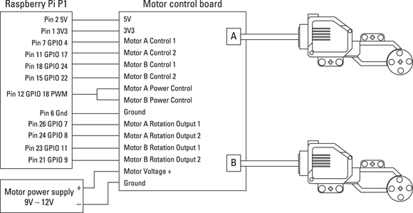
Figure 15-14: Connecting the motor drive to the Raspberry Pi.
Listing 15-1: Driving LEGO Motors
#!/usr/bin/env python
"""
Lego Motor Driver test 1 by Mike Cook June 2014
power (PWM) on GPIO 18 (12)
"""
import wiringpi2 as io
import time
mp = 18 # motor power pin (12)
a1 = 4 # motor A control 1 (7)
a2 = 17 # motor A control 2 (11)
b1 = 24 # motor B control 1 (18)
b2 = 22 # motor B control 2 (15)
ar1 = 7 # motor A rotational sensor 1 (26)
ar2 = 8 # motor A rotational sensor 2 (24)
br1 = 11 # motor B rotational sensor 1 (23)
br2 = 9 # motor B rotational sensor 2 (21)
motorControl = [(a1, a2), (b1,b2)]
print "Board Revision",io.piBoardRev()
print "If the program quits here start IDLE with 'gksudo idle' from the command line"
def main() :
pinInit() # define inputs and outputs
print "Python motor control test"
print "Ctrl C to quit"
while True:
allOff()
motor ="q"
motorToMove = 0
while not(motor == "A" or motor == "B") :
motor = raw_input("Motor to move A or B ")
motor = motor.upper()
if motor == "B" :
motorToMove = 1
turn = "s"
directionToMove = 0
while not(turn == "C" or turn == "A") :
turn = raw_input("Clock wise (c) or anti clock wise (a) ")
turn = turn.upper()
if turn == "A" :
directionToMove = 1
power = -1
while power < 0 or power > 100 :
power = input("Power 0 to 100 ")
pwm = 1024* (power / 100.0)
io.pwmWrite(18,int(pwm))
duration = -1
while duration < 0 :
duration = input("Time in seconds for motor to move ")
print "Turning on motor", motor, "for",duration,"seconds"
io.digitalWrite(motorControl[motorToMove][directionToMove],1)
time.sleep(duration)
io.digitalWrite(motorControl[motorToMove][directionToMove],0)
print "Turning off motor", motor
print
def allOff():
io.digitalWrite(a1,0)
io.digitalWrite(a2,0)
io.digitalWrite(b1,0)
io.digitalWrite(b2,0)
io.pwmWrite(mp,0) # motor off
def pinInit():
io.wiringPiSetupGpio()
io.pinMode(ar1,0) # input
io.pinMode(ar2,0) # input
io.pinMode(br1,0) # input
io.pinMode(br2,0) # input
io.pinMode(a1,1) # output
io.pinMode(a2,1) # output
io.pinMode(b1,1) # output
io.pinMode(b2,1) # output
io.pinMode(mp,2) # PWM mode
io.pwmWrite(mp,0) # off to begin with
if __name__ == '__main__':
main()
The code is reasonably straightforward. It starts by giving variable names to pin numbers, which means you can change things around by simply changing one line per pin. We’ve also defined the input pins here although they aren’t used in this program. We do this so the pins are set in a known state for the hardware in case they have been set to something else.
The pinInit function sets the library to use the GPIO numbering system to address the pins and sets them up as inputs, outputs, and a PWM output. Next, the code follows a series of user inputs to get the motor’s direction, the power, and the length of time it should be on. Each one of these is in a while loop that won’t exit until the user has made a valid choice. With the power input, a percentage value (0 to 100) is converted into the 0 to 1,024 value needed by the PWM signal. Note that unlike some other systems, full PWM is achieved at a value of 1,024 and not 1,023.
What pins to write to for the motor control are defined in a tuple list called motorControl. This is the clever part of the code. The motorToMove variable picks the first or second tuple in the list, and the directionToMove variable picks the first or second number in the tuple. So, the pin to set to high to get the correct motor turning in the correct direction is returned by the following:
motorControl[motorToMove][directionToMove]
This makes the actual setting of the correct pin much simpler than any long-winded collection of if statements.
We tested this with both our EV3 motors and NXT motors. Both would move at 13 percent power but no lower, which is to be expected. We noticed that, for a given power, the EV3 motor moved faster and made more noise than the NXT motor.
The motor’s sensors can be read as well. We used a simple sketch to try this out, as shown in Listing 15-2.
Listing 15-2: Reading the Motor’s Position Sensors
#!/usr/bin/env python
#!/usr/bin/env python
"""
Lego Motor Encoder input test
encoder 1 wired to GPIO 7 (pin 26) & 8 (pin 25)
encoder 2 wired to GPIO 11 (pin 23) & 9 (pin 21)
"""
import wiringpi2 as io
import time
motorId = ["A", "B"]
ar1 = 7 # motor A rotational sensor 1 (26)
ar2 = 8 # motor A rotational sensor 2 (24)
br1 = 11 # motor B rotational sensor 1 (23)
br2 = 9 # motor B rotational sensor 2 (21)
print "Board Revision",io.piBoardRev()
print "if the program quits here start IDLE with 'gksudo idle' from the command line"
io.wiringPiSetupGpio()
io.pinMode(ar1,0) # input
io.pinMode(ar2,0) # input
io.pinMode(br1,0) # input
io.pinMode(br2,0) # input
print "Hi from Python"
lastEncoder = [-1,-1]
count = [0,0]
upCode = 2
downCode = 1
while True:
port = [io.digitalRead(ar1)<<1 | io.digitalRead(ar2), @@ta io.digitalRead(br1)<<1 | io.digitalRead(br2)]
for e in range (0,2) :
encoder = port[e]
if lastEncoder[e] != encoder and lastEncoder[e] == 0:
if encoder == upCode:
count[e] +=1
elif encoder == downCode :
count[e] -=1
print "Motor",motorId[e]," moved ",count[0], count[1]
lastEncoder[e] = encoder
This follows the same convention as before in defining the input pins. You can move the motors by hand to make the encoders respond.
The endless loop combines the two sensors from each motor into a number that ranges from 0 to 3, by using the shift operator (<<) and logical ORing it with the other sensor using the bitwise OR operator (|) to get a two-bit number. This is put into a list called port. Then the current value of the sensor number is compared to the last one, and if the last one was 0, a count is incremented or decremented depending on whether the current sensor number is 2 or 1. If the current sensor number is 3, this indicates that a transition has been missed and you can’t be sure what direction it has moved in, so you do nothing with the count. This is part of the self-correcting nature of the Gray code. If the count has changed, then the new value of both counts is printed out.
In Python, printing takes a comparatively long time, so if you can avoid printing, you can cope with faster movement of the sensors.
Listening to Sensors
Communicating directly with LEGO sensors is not quite as easy as you may hope. The EV3 sensors use two methods: one for the simple touch sensor and the other for color, ultrasonic, Gyro, and IR sensors.
Touch sensors
The simplest sensor is the touch sensor. These are annoyingly different for the NXT and EV3 kits. Basically, they both consist of a switch and 2K2 series resistor. In the NXT version, the resistor is connected between pins 1 and 2 — sensor to ground. In the EV3, the resistor is connected between pins 6 and 4 — sensor and positive power rail. What’s annoying is that early NXT touch sensors didn’t have pins 2 and 3 connected together, so they won’t work with the EV3 brick unless you modify either the sensor or the cable to short these two wires. Figure 15-15 shows how to wire up a LEGO touch sensor to the Raspberry Pi for both types of sensors.

Figure 15-15: Wiring up a touch sensor.
All you need to do to read the touch sensor is to set a GPIO pin as an input and enable its pull-down resistor for an EV3 touch sensor, or enable the pull-up resistor for an NXT touch sensor. Note that the I2C lines have strong external pull-up resistors on the Raspberry Pi board, which will override any settings of the internal resistors. These are pins GPIO 0 and 1 on issue 1 boards and GPIO 2 and 3 on issue 2 boards. The code needed for reading this sensor is shown in Listing 15-3, which is essentially a simple switch input.
Listing 15-3: Reading a Touch Sensor
#!/usr/bin/env python
"""
Lego touch sensor test
"""
import wiringpi2 as io
import time
EV3touch = 10
NXTtouch = 25
print "if the program quits here start IDLE with 'gksudo idle' from the command line"
io.wiringPiSetupGpio()
io.pinMode(EV3touch,0) # input
io.pinMode(NXTtouch,0) # input
io.pullUpDnControl(EV3touch,1) # pull down activated
io.pullUpDnControl(NXTtouch,2) # pull up activated
lastEV3state = -1
lastNXTstate = -1
print"Lego touch sensor reading"
while 1 :
EV3state = io.digitalRead(EV3touch)
NXTstate = io.digitalRead(NXTtouch)
if EV3state != lastEV3state :
print "EV3 sensor now at",EV3state
if NXTstate != lastNXTstate :
print "NXT sensor now at",NXTstate
lastEV3state = EV3state
lastNXTstate = NXTstate
time.sleep(0.4)
The code will only print out the state of a sensor when it changes, which prevents lots of the same numbers from scrolling up the screen.
Advanced sensors
The advanced sensors that come with the EV3 kit are the color sensor, the IR sensor, the EV3 Ultrasonic sensor, and the Gyro sensor. The last two are supplied only in the Education Edition of the MINDSTORMS EV3 and not in the Home Edition. Fortunately, you can buy the sensors separately and download the “blocks” to use them with the Home EV3 software.
There is an NXT Ultrasonic sensor that will also work with the EV3 software, but they’re very different inside and what we’re about to show you won’t work with the NXT sensors.
The four advanced EV3 sensors communicate with the EV3 brick by serial communications using standard 5V logic levels. This is slightly odd because the EV3 brick is a 3V3 device, so there are buffers in the brick to cut down the 5V signal to a suitable level. However, there are no buffers that boost the 3V3 serial signal from the brick to the sensor. That means the sensors can cope with this voltage, so that simplifies things somewhat. The reason it works is because the Raspberry Pi is also a 3V3 system, so following LEGO’s example, there is no need to boost the transmit signal — you just have to cut down the 5V incoming signal.
There is quite a lot of complication involved in the protocol of the brick talking to a sensor, but a lot of this is taken up by the LEGO brick auto-identifying a sensor when it’s plugged in. This has to also accommodate the older NXT sensors, as well as third-party sensors and sensors that haven’t even been thought of yet. If you know what sensor you’re using, you can greatly simplify the software needed to talk to the sensor.
The sensor sends out a list of information about itself, which identifies its type, the modes it can operate in, the range of readings for each mode, and even the baud rate it wants to communicate in. All this happens at the slow rate of 2,400 bauds. When the brick has this information, it sends an acknowledgement and the sensor then switches to its preferred baud rate. Then the sensor sends data back continuously, with the brick sending an acknowledgement byte at least every 300 mS. If the brick fails to do this, the sensor reverts to the slow speed and starts sending its identification data again. This little dance is summed up in Figure 15-16.

Figure 15-16: The sensor initialization.
The sensor starts working in its default mode, which is Mode 0, the last one to have its information sent to the brick. Any time the sensor is sending information, the brick can command it to use another mode by sending it a command write message. The sensor continues in this mode until commanded into another mode, or it resets due to a power down or not receiving a NACK byte for 300 mS.
There is a further complication: The brick can tweak its own baud rate to match the sensor’s, which can be required because the sensor has no accurate crystal clock. Unfortunately, there is no way to do this on the Raspberry Pi because the baud rate is governed by dividing the fundamental clock frequency of the processor, so there is little point in describing that process, because there is nothing that can be done. We found that the sensors we have work correctly with the Pi without any adjustment, despite their baud rates being slightly off.
This information is sent back and forth in one of two ways: as a single byte or as a data packet. When the information is a single byte, this byte has its top two bits as zero, so they’re easily identifiable, whereas the start of packages have one or both of these bits set.
A package consists of three parts: a message type, a payload, and a single-byte check sum (see Figure 15-17).
- Message type: The message type byte is complex and is split up into a number of fields, as shown in Figure 15-18. The top two bits define the message type, the next three define the payload length, and the last three define the action. Note how the meaning of these last three bits changes depending on what sort of message is being sent. When this is an info or data message, these bits are simply the sensor’s current mode.
- Payload: The payload length indicates how long the body of the message is going to be. This is not a simple number like the mode number; instead, it’s an encoded value with the values shown in the diagram. The other twist to this is that an info message byte will be followed immediately by a command byte, making these sorts of messages a byte longer than any other message.
- Check sum: The check sum is calculated by performing an exclusive OR operation with all the previous bytes and with the number 0xFF (or 255 in decimal). When the data arrives, you can calculate the value of the check sum and see if it matches the value that is sent. If it doesn’t match, you know there is an error; if it does match, there is much less chance of there being an error. A simple check sum like this is not foolproof; you can get two or more errors that cancel out and give a false good. Other more complex check sum algorithms do exist, but something simple like this is good enough most of the time.
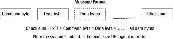
Figure 15-17: The format of a message package.

Figure 15-18: The first byte in a message.
To talk to the sensor with a Raspberry Pi instead of the EV3 brick, you need to understand this message structure and be able to replicate it. But first you have to connect the sensor and Pi together. The circuit to do this is shown in Figure 15-19, and it’s pretty straightforward. The GPIO pins brought out to the Raspberry Pi’s connector include two whose alternative functions include a serial port; these two pins are GPIO 14 and 15. The transmit pin (TX) can be connected directly to the sensor’s receive pin, but the 5V output from the sensor needs to be cut down with a potential divider to bring it into the 3V3 range.

Figure 15-19: The Raspberry Pi–LEGO sensor interface.
The parts list for this circuit follows:
- One 300R resistor (R1)
- One 1K resistor (R2)
- One 0.5mH inductor (optional)
- Two 0.1uF ceramic capacitors (C1, C2)
- Stripboard, 1 x 2 inches
- LEGO connector socket
- Four-way 0.2-inch pitch screw connector
If you’re eagle-eyed, you may say, “That 300R resistor is too low. It should be 510R to get 5V down to 3V3.” And you would be right, if not for one hidden fact: The sensor itself includes a 220R resistor in series with this line already, so you only need to add another 300R to give, in effect, a 520R resistor for the top of the potential divider. So, this circuit is suitable only for LEGO sensors, not general-purpose 5V serial inputs.
The only other thing that may surprise you about this circuit is the inductor in the power line. In fact, you can do without it, but the Raspberry Pi will reset every time you plug a sensor in. This is because the sudden inrush of current to the sensor causes the 5V line on the Raspberry Pi to dip to a point where the reset is triggered. What the inductor does is limit the sudden inrush and prevent a reset. The actual value isn’t critical, and it can be absolutely any value above that shown in the diagram. A series diode also does the trick of preventing reset, but it reduces the voltage going to the sensor and messes up the readings from the color sensor. Replace the inductor with a piece of wire if you don’t mind the reset. We built this up on a small piece of stripboard, as shown in Figure 15-20.
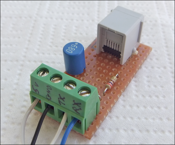
Figure 15-20: The built Raspberry Pi–LEGO sensor interface.
If you’re wondering where capacitors C1 and C2 are, they’re surface mount capacitors mounted on the underside, but you can use a leaded capacitor if you prefer.
The Raspberry Pi software
In order to successfully use a sensor directly with the Raspberry Pi, you have to write a program to handle the initialization protocol. This mainly involves writing a function that will read the serial port and split up what comes out into individual messages. To start off, let’s look at how to read and display the identification information coming from the sensor and display it.
The Raspberry Pi’s serial port is used during the boot-up process. So, to prevent the sensor from interfering with the boot up, you must disable getty. Here’s how:
- Use the File Manager to navigate to the directory
/etc/. Choose Tools⇒Open Current Folder as Root.
A new window appears.
- Right-click the file
inittaband choose Open with Leafpad. - Now find the line that says the following, and comment it out by putting a
#in front of it:T0:23:respawn:/sbin/getty -L ttyAMA0 115200 vt100 - Save the file.
- To stop the Raspberry Pi from sending out data to the port, with the root view in the File Manager go to the
/boot/ directoryand open thecmdline.txtfile. - Find the line that says the following and delete it:
console=ttyAMA0,115200 kgdboc=ttyAMA0,115200 - Save the file and reboot the Pi.
- If you don’t have the Python serial module, install it from a command-line window by typing the following:
sudo apt-get install python-serial
Now you’re all set to go. You can type in the code shown in Listing 15-4, which will basically monitor the serial port until the sensor has finished sending all its data and then send a byte command to trigger the sensor into its high-speed mode. Then it will write to the sensor the required operating mode and milk the data by sending a NACK command every 230 mS and display the data package sent after that.
Listing 15-4: Reading a Serial EV3 Sensor
#!/usr/bin/env python
# Serial sensor by Mike Cook June 2014
# Raspberry Pi serial sensor tested with the EV3 color sensor and IR sensor
# It should also work with the EV Ultrasonic sensor (not the NXT one) and the EV3 Gyro
import time
import serial
SYNC = 0x00 # Synchronization byte
ACK = 0x04 # Acknowledge byte
NACK = 0x02 # Not acknowledge byte
payloadLookup = [1, 2, 4, 8, 16, 32, 0, 0]
messageLength = 0
# to fit max message plus command and checksum
message = [ n for n in range(0,34) ]
refreshTime = 0.230 # Rate to read data must be less than 300 mS
checkSumError = False
ser = serial.Serial('/dev/ttyAMA0', 2400, timeout =2 )
def main() :
print "Sensor read"
setup()
mode = 0 # sensor mode to use
changeMode(mode)
print "running in sensor mode",mode
lastRefresh = time.time()
while True :
if time.time() - lastRefresh > refreshTime : # send NACK and look at data
ser.write(chr(NACK))
lastRefresh = time.time()
ser.flushInput() # remove old data
getMessage() # get the data
if not checkSumError :
printMessage() # view data message
def setup():
global ser
print "initializing the sensor"
while not(message[0] == 0x90 and message[1] == 0x80 and @@ta
checkSumError == False) :
getMessage()
if ord(ser.read(1)) != ACK :
print("not got an ACK");
ser.write(chr(ACK)) # tell the sensor to go
time.sleep(0.006) # give it time to finish sending the ACK
ser.close()
ser = serial.Serial('/dev/ttyAMA0', 57600, timeout =2 )
def getMessage() : # parse input stream into message
global checkSumError, messageLength
checkSum = 0xff
command = ord(ser.read(1))
if command == 0x00 or command == 0xff : # color sensor sometimes @@ta
throws these
return
message[0] = command
if (command & 0xC0) == 0 : # single byte
pass
else : # multibyte message
checkSum ^= command;
payloadLength = payloadLookup[(command >> 3) & 7] # number bytes @@ta
in message
if(command & 0xC0) == 0x80 :
payloadLength += 1 # info message has command byte following
for n in range(1, payloadLength + 1) : # read in the message up to the check sum
message[n] = ord(ser.read(1))
checkSum ^= message[n]
# get check sum
message[payloadLength + 1] = ord(ser.read(1))
messageLength = payloadLength + 1
if message[payloadLength + 1] != checkSum :
checkSumError = True # check sum error
else :
checkSumError = False # check sum fine
def printMessage() : # not the check sum
for n in range(0,messageLength) :
print hex(message[n]),
print
def changeMode(newMode):
if newMode <= 5 and newMode >= 0 :
sendMessage(0x44, 0x11) # command write
for n in range(0,3) :
sendMessage(0x43, newMode & 0x7) # command mode
ser.write(chr(NACK));
def sendMessage(cmd, data):
cSum = 0xff ^ cmd ^ data;
ser.write(chr(cmd))
ser.write(chr(data))
ser.write(chr(cSum))
if __name__ == '__main__':
main()
The main function starts off by calling the setup function, which reads what the sensor is sending until the final message in the sequence. This is always the data format of the sensor’s mode zero. Then the sensor should send an ACK byte to say it’s ready to switch into sending the data. At this point, you have 80 mS to reply with an ACK byte or the sensor will start sending its data again. The setup function sends this and then sleeps for a short time to allow the byte to be sent. Then the serial port is closed and opened again using the faster speed before returning. Then the main function writes to the sensor the mode you want to operate it in. By default, this is mode 0, but if you want to change it, the code is provided to do so. Changing the mode is simply done by sending three bytes — the command, mode number, and check sum. We noticed that the LEGO brick sometimes sends this message a few times, so this code sends it three times, followed by a NACK byte. This is done in the functions changeMode and sendMessage. Notice that this last function also generates the check sum by using ^ the exclusive OR operator.
The while loop runs forever. Here, the system timer is used so that once every 230 mS (to give Linux a bit of slack when it steals time from you) the Raspberry Pi keeps the sensor alive by giving a NACK byte, flushing the serial buffer, and reading and printing out the next data message sent. This is done because the sensor sends data continuously and not every NACK, so the buffer will have old data in it. If you want to do something with data coming faster, you can simply read the message as often as you need to.
The heart of the program is the getMessage function. This reads data a byte at a time from the serial port and analyzes it to see how many bytes are in the message. Then it goes on to read those bytes and calculate and verify the check sum. This keeps the input data stream in sync. The result is a sequence of data messages like this:
0xc0 0x48
0xc0 0x4a
0xc0 0x4c
This is for an IR sensor running in mode 0 proximity and represents the distance to an object in front of it. Most of the time, the data is in the second byte, but in the case of reading the numbers from the IR remote, there are four bytes; the one populated with the key number depends on the channel the remote is set to. We didn’t get much joy from the angle measurement seek mode, however, because the data returned seemed inconsistent.
It isn’t possible to print out the information messages as you go because printing in Python takes a long time and you lose the synchronization between the data coming in and the need to respond to it. We wrote a much longer program that will print out and decode all the messages the sensor sends and then, in effect, does what this program does. You can find that program along with a text file of its output from the IR sensor on www.dummies.com/go/raspberrypiprojects.