
Chapter 9
Advanced Interfaces
In This Chapter
![]() Converting analog to digital
Converting analog to digital
![]() Building an analog-to-digital converter
Building an analog-to-digital converter
![]() Using a potentiometer
Using a potentiometer
![]() Creating an analog temperature sensor
Creating an analog temperature sensor
![]() Interfacing with an analog-to-digital microchip
Interfacing with an analog-to-digital microchip
The Raspberry Pi general-purpose input/output (GPIO) pins are capable of detecting digital signals — either high or low. The problem is, the world we live in is a lot less black-and-white than that. For example, what if you want to detect light, sounds, temperature, or pressure? A digital signal isn’t going to cut it. Instead, you need the ability to detect a range of electronic signals, and that’s where analog signals come in.
One of the shortcomings of the Raspberry Pi is that it doesn’t have any analog inputs. But you can easily solve this problem by using an analog-to-digital converter. In this chapter, you build your own converter, learn about different conversion methods, and write software for each. Toward the end of the chapter, we look at a high-precision analog-to-digital converter microchip.
Converting Analog to Digital
The Raspberry Pi’s digital inputs can detect binary signals, which are either high or low represented by either 0V or 3.3V. However, an analog signal consists of a range of voltages. A 5V analog sensor, for example, may output voltages from 1.5V to 5V. An analog-to-digital converter (sometimes known as ADC, A-to-D, or A/D) converts the variable voltage to a reading that can be interpreted by the digital microprocessor or, in our case, the Raspberry Pi.
But how do you determine a variable voltage when all you have is a digital input that has only two states?
One method that is frequently used by microprocessors is to treat the analog sensor like a resistor connected to a capacitor and time how long it takes to charge up a capacitor. Capacitors don’t charge instantly; the amount of time they take to charge varies depending on the voltage. Unfortunately, this method isn’t very accurate on the Raspberry Pi, because the Linux operating system can’t accurately measure clock cycles, so your results would be inaccurate. Additionally, this method works only on analog devices that act as resistors like potentiometers, temperature sensors (thermistors), and photocells.
Another method is to compare the analog voltage to a known reference voltage. Using a device called a comparator, we can determine if one voltage is greater than the other. Even though you don’t know the analog voltage level, the comparator will tell you when your reference voltage is greater than the analog voltage. By comparing one voltage to the other, you can make a series of calculated guesses to determine the analog voltage.
Figure 9-1 demonstrates how you can increase your known reference voltage and perform series of tests using a comparator. When you receive a positive result from the comparator, you know the analog voltage is somewhere between the current and previous levels.

Figure 9-1: Use a comparator to compare a known voltage to an unknown voltage in order to determine the unknown voltage.
Comparators are often associated with analog-to-digital conversion because of their ability to compare two voltages. A comparator compares the voltage of two inputs and outputs a digital signal indicating which is larger. Figure 9-2 shows a diagrammatic representation of the LM339 comparator, which has four analog inputs and 14 pins in total — 8 inputs, 4 outputs, and 2 pins for +VE and GND. (The LM339 is available from electronics stores or online, and it’s very affordable.) The comparator is one of the components you use to build an analog-to-digital converter later in this chapter.

Figure 9-2: A diagram of the LM339 comparator chip.
The pulse width modulation (PWM) is the component that enables you to vary the voltage going into the comparator, which makes the method shown in Figure 9-1 possible on the Raspberry Pi. PWM works by regulating energy using a succession of pulses, known as the pulse train. By increasing or decreasing the pulse width, you can regulate energy flow. PWM is often used to regulate the brightness of an LED by making the LED blink on and off at different frequencies, which makes it look bright or dim. As long as it blinks faster than the persistence of our vision, you don’t see it flickering. The analog-to-digital converter uses PWM to alter the DC voltage of the reference voltage going into the comparator.
Figure 9-3 shows how you can alter the voltage by changing the waveform of the signal. If the average high state of the pulse train is high, then the voltage will be high; if the average high state of the pulse train is low, then the DC voltage will be low.

Figure 9-3: Pulse width modulation can be used to alter DC current.
GPIO 18 on the Raspberry Pi can be configured for PWM. In order to create a digital pulse train, you connect GPIO 18 to the positive end of a comparator and a test voltage to the positive end of the comparator. When the test signal is higher, the comparator will output a positive digital signal; when it’s lower, the comparator will output a negative signal.
We will use a low-pass filter on the PWM signal, which has a smoothing effect and produces a DC output that is connected to the –VE side of the comparator. The filter attenuates the high frequencies and lets through the lower ones. A common method to create a low-pass filter is to use a resistor and a capacitor in series to smooth the signal. The test voltage is connected to the +VE side of the comparator. As shown in Figure 9-4, the output from the comparator tells us whether the test signal is greater or less than the PWM. We can alter the DC current of the input using PWM from the Raspberry Pi, which gives us a method of guessing the test voltage. Later in this chapter, we examine three commonly used methods of guessing the test voltage. You use PWM, a comparator, and a low-pass filter to build an analog-to-digital converter later in this chapter.

Figure 9-4: Use a comparator to convert the PWM waveform into a digital pulse train.
Considering the accuracy of analog-to-digital conversion
The intersection of the analog voltage (A) and the reference voltage (B) is approximate (refer to Figure 9-1). You can get very close to the analog voltage reading, but you’ll never get the exact reading. Analog-to-digital converters are usually described by their resolution, which represents the range of readings they’re capable of producing. For example, an analog-to-digital converter that has a resolution of 8 bits can produce a range of 256 readings (28 = 256). A 10-bit converter has a resolution of 1,024 (210 = 1,024). An analog signal is a range of electronic signals, so the higher the bit rating of the converter, the bigger the range of analog signals it can support.
 The resolution gives you the range of readings it can support, but it isn’t an indication of the converter’s accuracy. The data sheet of most analog-to-digital converters tells you the converter’s accuracy ratings, which describes the potential variance between the analog signal and the digital reading.
 These variances are usually given in the unit of least significant bits (LSBs). The LSB is the rightmost bit of a number. For example, a 10-bit number is represented in binary as a ten-digit number of ones and zeroes (for example, 1111111000). The three zeroes are the least significant bits. If a 10-bit analog-to-digital converter has an accuracy of 2 LSB, that means its actual accuracy is 8 bits.
This explains an important difference between an analog-to-digital converter’s resolution and its accuracy. The accuracy of an analog-to-digital converter is nonlinear. The extent of the variance changes depending on the voltage. This is called nonlinearity, meaning the accuracy is nonlinear to the voltage.
Another aspect of accuracy is repeatability. You see during the course of this chapter that all the analog-to-digital converters and methods we use produce a reading that is very close to the analog signal, but that reading is constantly fluctuating. (We explore methods to minimize — or even eradicate — the inaccuracy.) This constant change is called the analog-to-digital converter’s repeatability. Any analog-to-digital converter can only give a reading of +/–1 LSB.
In this chapter, we compare the accuracy of different conversion methods and make tradeoffs between conversion time, resolution, and the filter to design an analog-to-digital converter that suits your need.
Making sense of a digital reading
You may be wondering, “What does the digital reading mean?” We’ve explained that analog-to-digital converters can have different resolutions and can produce readings within the range of the resolution. But what does a reading of 524, for example, out of a possible 1,024 actually mean?
In order to make the reading meaningful, you need to understand its relationship to the analog signal. One way to do this is to convert the reading into a value representing the analog voltage. The analog-to-digital converter has a maximum reference voltage. The reference voltage gives you a yardstick to calculate the analog voltage value from the digital reading.
For example if a 10-bit analog-to-digital converter has a reference voltage of 5V and produces a reading of 310, then the analog voltage is
(311 ÷ 1,024) × 5 = 1.519V
However, knowing the analog voltage doesn’t always mean that much. For example, a potentiometer connected to a 10-bit analog-to-digital converter will produce a reading of 0 when turned all the way to the left and 1,023 when turned all the way to the right. Having a reading between 0 and 1,023 for a potentiometer probably makes more sense to you than a voltage from 0V to 5V, for example. It all depends on what information you require from the analog device.
 Understanding the relationship between the digital data you receive from the analog-to-digital converter back to the sensor is an important aspect of your design.
Introducing the Analog-to-Digital Conversion Methods
In this section, we introduce you to three commonly used methods for analog-to-digital conversion. Later in the chapter, we walk you through each method in greater detail.
Each of these methods uses a comparator to compare two voltages and make a series of guesses to try to get as close as we can to discovering the analog voltage.
The ramp method
If an analog sensor has a voltage of 1.75V and you compare it to a known reference voltage that starts at 0V and increments until the reference voltage is greater than the analog voltage, you know that the analog voltage is somewhere between the reading just before 1.75 and after 1.75. This method is known as the ramp method.
The reference voltage in the ramp method starts at zero and increases in small amounts until it’s greater than the analog voltage (shown as the trip point in Figure 9-5). To increase accuracy, you can make each step as small as possible, but this adds to the amount of time needed to produce a reading — taking smaller steps means doing more tests on the comparator, which takes time.

Figure 9-5: The ramp method.
The successive approximation method
The successive approximation method uses a series of calculated guesses to home in on the answer. The starting point can be half of the maximum voltage and is either increased or decreased depending on whether the comparator has tripped. The increment or decrement value is halved with each guess, as shown in Figure 9-6. As with the ramp method, you can increase the amount of guesses to get a more accurate result, which takes more time.

Figure 9-6: The successive approximation method.
Successive approximation may look much faster than the ramp method because you can get a very accurate answer in 8 guesses, whereas with the ramp method you could make 1,023 guesses. But successive approximation requires more filtering time — the signal is changing so much between guesses that the filter needs more time to settle. The ramp method takes small increments in one direction, which enables the filter to produce an accurate result with much less settling time. When designed with a fast and accurate filter, successive approximation is faster than the ramp method. Many analog-to-digital conversion chips (like the MCP3008, which we use later in this chapter) use this method for conversion.
The tracking method
The tracking method uses the ramp method to determine the first value and then tracks the analog voltage using the previous reading as a starting point for the next search, as shown in Figure 9-7. The comparator tells you which direction to search for the analog voltage. Using the previous reading as a starting point reduces the number of steps you need to take. This method is fast if the analog voltage doesn’t change very frequently (for example, because you have a temperature sensor that changes fairly slowly over time).

Figure 9-7: The tracking method.
Building an Analog-to-Digital Converter
In this section, you build an analog-to-digital converter and write the code for each of the three conversion methods explained in the previous section. The converter uses a comparator (refer to Figure 9-2) and pulse width modulation on the Raspberry Pi, as explained earlier in this chapter, to convert the analog signal to a digital reading on the Raspberry Pi.
Finding the parts you need
To make this project, you need the following parts:
- Five 3K3 ohm 0.5W carbon film resistors ±5 percent
- One 10k ohm 0.5W carbon film resistor ±5 percent
- One 1k ohm 0.5W carbon film resistor ±5 percent
- One 1uF/50V radial electrolytic capacitor
- Two 0.1uF/50V radial electrolytic capacitors
- One LM339 quad comparator (a device used to compare voltages and output the result in a digital signal)
- One Humble PI prototyping board (a prototyping board for the Raspberry Pi from CISECO) or one solderless breadboard (a prototyping board where parts and wires can be connected by clipping them into the board; used for prototyping electronics without having to solder parts together)
- Three 2-pin 0.2-inch (5mm) screw terminals
- Assorted jumper wires for the prototyping board or for the solderless breadboard ( Note: If you’re using a breadboard, use male-to-male for breadboard connections and male-to-female for connecting the breadboard to the GPIO pins. Jumper wires usually come in packs of various quantities, colors, and sizes. Any size will do for this project, but shorter male-to-male [10cm] and longer male-to-female [20cm] are best.)
- One 10K breadboard trim potentiometer
All these parts are readily available from electronic stores or online. We use a Humble PI breakout board from CISECO because it attaches right to the Raspberry Pi GPIO header and has a center power rails and holes arranged in threes, making it a very convenient layout. You can substitute it for a regular prototype board with center rails or a solderless breadboard, but you’ll need to make the necessary adjustments because a breadboard has the power rails running down the outside and not down the center.
Since the release of the Raspberry Pi 2 A++, and B++ models, the shape of the board has changed, so some breakout boards (like the Humble PI) no longer fit the Raspberry Pi. However you can use an extra-tall stacking header Raspberry Pi that allows you to connect the Humble PI to the new shape of the Raspberry Pi.
Constructing the circuit
The difficulty level of the prototype board construction will be difficult for a complete beginner because there are around 50 solder points. If you’re a total beginner, you may want to opt for the breadboard. However, even if you’re a soldering novice, you should be able to construct this prototype.
As with all prototyping, make sure you understand each part before you begin construction. This understanding will help you troubleshoot and test different parts of the circuit during or after the build. Figure 9-8 is the circuit diagram for the analog-to-digital converter.

Figure 9-8: A circuit diagram for the analog-to-digital converter.
Take note that in later revisions of the Raspberry Pi, GPIO 21 changed to GPIO 27, but the Raspberry Pi pin number using the in code remains the same.
Understanding the circuit
The left side of the circuit in Figure 9-8 controls the voltage going into pins 6, 8, and 10 of the comparator. You configure the Raspberry Pi pin 18 to the PWM mode and adjust its value from 0 to 1,023. This variable voltage is known as the reference voltage. This moves the voltage going into pins 6, 8, and 10 in small increments from 0V to 5V. The 1uF capacitor and 10K resistor are the low-pass filter (refer to “Converting Analog to Digital,” earlier in this chapter, for more details), which converts the PWM pulses into DC current.
The three analog inputs shown in Figure 9-8 can be connected to your analog sensors. We only use one of the analog inputs in this chapter, but we’ve designed the converter with three inputs to give you more options if you need them for other projects. Later in this chapter, you test this circuit using a potentiometer and a temperature sensor. The comparator compares the voltages of the reference voltage to the analog voltage. When the comparator pins 1, 14, and 13 flip from low to high, you know the reference voltage is greater than the analog voltage. When this happens, the input pins on the GPIO (pins 17, 21, and 4) go high. Each of these pins has a 3K3 pull-up resistor connected to it. Lastly, the comparator is powered by 5V going to pin 3 and is grounded on pin 12.
Constructing the circuit
Figure 9-9 shows a grid of the Humble PI prototype board with the x- and y-coordinates of each connection. Each hole in the board is identified by the row and column numbers given at the top and on the left side of the diagram. The positive and negative center rails are labeled as + and –. For example, there is an R1 resistor connected from position E5 to position +5. Table 9-1 shows the position of every component, including jumper wires.

Figure 9-9: Analog-to-digital prototype board schematic.
Table 9-1: Analog-to-Digital Converter Components
|
Component |
From |
To |
|
LM339 |
I11 |
H11 |
|
LM339 |
I12 |
H12 |
|
LM339 |
I13 |
H13 |
|
LM339 |
I14 |
H14 |
|
LM339 |
I15 |
H15 |
|
LM339 |
I16 |
H16 |
|
LM339 |
I17 |
H17 |
|
R1 |
+19 |
J19 |
|
R1 |
–20 |
K20 |
|
C1 |
–21 |
K21 |
|
Jumper |
K21 |
K20 |
|
Jumper |
K20 |
K19 |
|
Jumper |
M9 |
M8 |
|
R2 |
N4 |
N8 |
|
R3 |
J8 |
M8 |
|
Jumper |
I8 |
B14 |
|
Jumper |
M4 |
N3 |
|
C1 |
–4 |
L4 |
|
C2 |
–9 |
I9 |
|
Jumper |
B14 |
J9 |
|
LM339 pin 1 (GPIO17) |
C7 |
B3 |
|
LM339 pin 1 (R1) |
J11 |
D5 |
|
LM339 pin 2 (R2) |
K12 |
L8 |
|
LM339 pin 3 (5V) |
K9 |
K13 |
|
LM339 pin 4 (R1) |
K19 |
K14 |
|
LM339 pin 5 (GPIO18) |
J15 |
B4 |
|
LM339 pin 6 (R2) |
L3 |
J16 |
|
LM339 pin 7 (T2) (analog 1) |
L20 |
J17 |
|
LM339 pin 8 (R2) |
M3 |
G17 |
|
LM339 pin 9 (T3) (analog 2) |
L22 |
G16 |
|
LM339 pin 10 (R2) |
N3 |
G15 |
|
LM339 pin 11 (T3) (analog 3) |
L24 |
G14 |
|
LM339 pin 12 (GND) |
G13 |
-22 |
|
LM339 pin 13 (GPIO4) |
C5 |
B10 |
|
LM339 pin 13 (R1) |
G12 |
D7 |
|
LM339 pin 14 (R1) |
G11 |
D6 |
|
LM339 pin 14 (GPIO21) |
C6 |
B5 |
|
T1 (+3V) |
L14 |
B14 |
|
T1 (+5V) |
L16 |
B14 |
|
T2 (GND) |
L18 |
–24 |
|
Jumper |
G16 |
L22 |
|
PWR Center Rail (+3V) |
+26 |
B13 |
|
GND Center Rail (GND) |
–26 |
–VE |
First, place all components onto the prototype board without solder. Double-check that they’re all in the right position and then begin soldering. Be careful not to spill solder over to any adjacent holes. When all the components are soldered in place, solder in the jumper wires. We recommend placing the jumper wires underneath the board and the electrical components above the board, as shown in Figure 9-10. Some of the jumps can be completed just by using solder to bridge two adjacent pads (for example, M3 to M4).

Figure 9-10: The Raspberry Pi analog-to-digital converter.
Before powering it up, use a circuit tester to test each connection. Circuit testers can be bought or constructed using an LED circuit. Some multimeters have a circuit tester built in. They consist of a battery connected to a light or a buzzer that indicate when the circuit is closed. The tester has two leads that, when joined, close the circuit and activate the light or buzzer. You can use the circuit tester to test each connection of the analog-to-digital converter. For example, the right side of the 10k resistor should be connected to pins 6, 8, and 10 of the LM339 comparator. In order to test these connections, place one of the circuit tester leads on the right side of the 10k resistor and then touch pins 6, 8, and 10 of the comparator. Your circuit tester will indicate if each of these three circuits is soldered correctly. Use this method to test every connection.
The Humble PI can be powered by external power (refer to the pads on the top-right corner of the board), but we’ve chosen to power the board directly from the Raspberry Pi by connecting the 3V (A13) to PWR and connecting GND to the negative power rail (–).
The six screw terminals can be used to connect to an analog sensor. There is a screw terminal for the three analog sensors — 5V, 3V, and GND — as shown in Figure 9-9.
Connecting an analog sensor
Now that you have your analog-to-digital converter built, you can connect it to an analog sensor. To start, connect it to a potentiometer (also known as a pot or a trimpot). Connect the left pin of the trimpot to the 3V screw terminal, the middle pin of the trimpot to the Analog 1 screw terminal, and pin 3 of the trimpot to the GND screw terminal (see Figure 9-11).
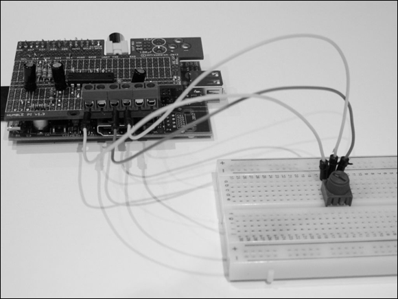
Figure 9-11: Connecting a potentiometer to the analog-to-digital converter.
Writing the software
In this section, you write code for each of the analog-to-digital conversion methods explained earlier in this chapter. You use C code for the interfaces because it’s faster than Python, but we also show you how to call a C program from Python so you can write Python programs to interface with your analog sensors.
Software for the ramp method
The software for the ramp method is in Listing 9-1. Type the program in and save it to a file called ramp.c.
Listing 9-1: Analog-to-Digital C Program for the Ramp Method
/*
* ramp.c
* Raspberry Pi Projects For Dummies: Analog-to-Digital Converter
* Ramp Method
*/
#include <wiringPi.h>
#include <stdio.h>
#include <stdlib.h>
#include <stdint.h>
float to_volts(int reading, float analog_volts);
int main (int argc, char *argv[])
{
int one_reading;
int ramp, reading0, reading1, reading2;
unsigned char gotReading0, gotReading1, gotReading2;
const unsigned char A0 = 17, A1 = 21, A2 = 4, pwm = 18;
if (argc!=2){
   printf ("usage : ramp [single_reading 1/0]
");
exit(1);
}
one_reading = atoi(argv[1]);
if (wiringPiSetupGpio () == -1)
exit (1);
pinMode (A0,INPUT);
pinMode (A1,INPUT);
pinMode (A2,INPUT);
pinMode (pwm, PWM_OUTPUT) ;
pwmWrite(pwm, 0);
delay(40);
for (;;)
{
reading0 =-1;
reading1 =-1;
reading2 =-1;
gotReading0 = 0;
gotReading1 = 0;
gotReading2 = 0;
for (ramp = 0 ; ramp < 1024 ; ramp+=4) // in effect 8 bit
{
pwmWrite (pwm, ramp);
delayMicroseconds(200);
if(gotReading0 == 0 && digitalRead(A0)== 0){
gotReading0 = 1;
reading0 = ramp;
}
if(gotReading1 == 0 && digitalRead(A1)== 0){
gotReading1 = 1;
reading1 = ramp;
}
if(gotReading2 == 0 && digitalRead(A2)== 0){
gotReading2 = 1;
reading2 = ramp;
}
if(gotReading0 && gotReading1 && gotReading2) break;
}
printf("Reading Ch0 = %d (%2.3fV) Ch1 = %d (%2.3fV) Ch2 = %d (%2.3fV)
", reading0, to_volts(reading0,5), reading1, to_volts(reading1,5)
, reading2, to_volts(reading2,5));
if (one_reading) {
return(0);
}
pwmWrite (pwm, 0);
delay(40);
}
return 0 ;
}
float to_volts(int reading, float analog_volts)
{
float volts;
volts = ((float)reading / 1023) * analog_volts;
return(volts);
}
The program sets GPIO 18 to PWM mode and then loops through each PWM setting starting at 0 and ending at 1,023. To speed it up, we set it to increase in steps of 4. Looping 256 times instead of 1,024 will make the program faster but sacrifice 2 bits of resolution. With each loop cycle, you check the GPIO digital pins to see if one of the comparators has flipped from low to high and, if so, save the reading for that sensor. When all three sensor values have been read or you reach the end of the loop, the program writes the results to the screen and goes again into the loop to get the next reading.
Compile the program using the following command:
$ sudo gcc -o ./ramp ramp.c -l wiringPi
You pass a parameter of 0 or 1 to the program that determines whether the program will print only one reading or multiple readings. If it’s the latter, you press Ctrl+C to quit. Now run the program from the command line using the following command:
$ ./ramp 0
You see the output printed to the screen for each of the three analog channels. Adjust the trimpot by turning the knob left and right, and watch the value of channel 0 move up and down. Then stop adjusting the potentiometer and observe the results. Notice that even though the potentiometer is not changing, the reading fluctuates. The spread between the minimum and maximum reading we get is about 8, as shown here:
Reading Ch0 = 540Reading Ch0 = 536Reading Ch0 = 544
Our goal is to try get to a steady reading with little to no fluctuation. One way you can reduce the fluctuation is to refine the granularity of the PWM cycle. The ramp.c program loops through 0 to 1,023 PWM setting in increments of 4 as per the following line of code:
for (ramp = 0 ; ramp < 1024 ; ramp+=4) // in effect 8 bit
It will loop 256 times, which equates to 8-bit accuracy (28 = 256). With the fluctuation, we’re losing around 3 bits, so our converter is, in effect, a 5-bit converter. You can improve this by taking smaller increments and increasing the loop cycle to the full 1,024 settings available on the Raspberry Pi PWM. Change the following line to:
for (ramp = 0 ; ramp < 1024 ; ramp+=1) // in effect 10 bit
Recompile and run the program. You should now see a more accurate result. Our results are as follows:
Reading Ch0 =
197
Reading Ch0 = 198Reading Ch0 = 199Reading Ch0 =
202Reading Ch0 = 197Reading Ch0 = 197
The spread of the fluctuation is now 5. We’ve improved the accuracy of the analog-to-digital converter, but we paid a price in time. The converter is now half the speed it was originally, and it’s noticeable.
Another change you can make to improve accuracy is to adjust the settling time given to the circuit with every change of the PWM cycle. The first of the following two lines changes the PWM value and the second pauses the program for 200 microseconds while the circuit settles.
pwmWrite (pwm, ramp);delayMicroseconds(200);
Change the 200 to 500 and recompile and run again. Our results improved to a spread of only 2. However, there is an even more noticeable degradation to the performance of the conversion.
Reading Ch0 =
178
Reading Ch0 = 178Reading Ch0 =
180
A third modification that could be made is to fine-tune the low-pass filter by reducing the cut-off frequency. The settling time is governed by the action of the filter. Again, there’s a performance trade-off to be made because the lower the cut-off frequency, the longer it takes for the resulting voltage to ramp up to the final value. This would mean changing the 1uF capacitor and the 10k resistor, which would require a change to the circuit, so for the purposes of this chapter we won’t go into the different options here.
Software for the successive approximation method
Listing 9-2
is the code for the successive approximation method. The program performs eight guesses at the analog voltage. With each guess, the comparator tells you if you’re higher or lower than the analog voltage, and then the next guess is either increased or decreased by half the previous increment. With each guess, you home in on the answer. Type the program in and save it to a file called succ.c.
Listing 9-2: Analog-to-Digital C Program for the Successive Approximation Method
/*
* succ.c
* Raspberry Pi Projects For Dummies: Analog-to-Digital Converter
* Successive Approximation Method
*/
#include <wiringPi.h>
#include <stdio.h>
#include <stdlib.h>
#include <stdint.h>
int successive(char ch);
float to_volts(int reading, float analog_volts);
int main (int argc, char *argv[]){
int one_reading;
int reading0, reading1, reading2 ;
const unsigned char A0 = 17, A1 = 21, A2 = 4;
if (argc!=2){
  printf ("usage : succ [single_reading 1/0]
");
exit(1);
}
one_reading = atoi(argv[1]);
if (wiringPiSetupGpio () == -1)
exit (1) ;
pinMode (A0,INPUT);
pinMode (A1,INPUT);
pinMode (A2,INPUT);
pinMode (18, PWM_OUTPUT) ;
for (;;){
reading0 =-1;
reading1 =-1;
reading2 =-1;
reading0 = successive(A0);
reading1 = successive(A1);
reading2 = successive(A2);
     printf("Reading Ch0 = %d (%2.3fV) Ch1 = %d (%2.3fV) Ch2 = %d (%2.3fV)
",
reading0, to_volts(reading0,5), reading1, to_volts(reading1,5),
reading2, to_volts(reading2,5));
if (one_reading==1)
return(0);
}
return 0 ;
}
int successive(char ch){
int reading = 512; // start at the midpoint
int x = 256,i,pwm = 18;
for(i=0; i<8; i++){
pwmWrite(pwm,reading);
delayMicroseconds(3000); // settling time
if(digitalRead(ch) == 0){
reading=reading-x;
}
else {
reading=reading+x;
}
x=x/2; //narrow the search
}
return (reading);
}
float to_volts(int reading, float analog_volts)
{
float volts;
volts = ((float)reading / 1023) * analog_volts;
return(volts);
}
Compile the program using the following command:
$ sudo gcc -o ./succ succ.c -l wiringPi
You pass a parameter of 0 or 1 to the program that determines whether the program will print only one reading or successive readings. If it’s the latter, you press Ctrl+C to quit. Now run the program from the command line using the following command:
$ ./succ 0
Using this method, you can obtain the same result as the ramp method, except with the ramp method you could potentially have to make 256 guesses as opposed to 8 using this method. One major disadvantage of this method is the settling time (3,000 microseconds) that the circuit needs before it takes a new reading. This is due to the fact that we’re making large jumps in voltage with each guess. The ramp method, however, increments the voltage in small increments in the same direction so you can dramatically reduce the settling time (75 microseconds).
Here’s is a comparison of the total potential settling time of each method:
Total settling time for the ramp method:
256 × 75 = 19,200 microseconds
Total settling time for the successive approximation method:
3,000 × 8 = 16,000 microseconds
Even though the ramp method takes many more guesses, it’s only marginally slower than successive approximation.
As with the ramp method, a number of factors will affect the accuracy of the conversion. In the preceding section, we explain how you can fine-tune the settling time, the granularity of the PWM settings, and the low-pass filter. The same applies with this method.
You can increase or decrease the amount of guesses it makes by adjusting the 8 in this form loop statement to your desired value:
for(i=0; i<8; i++){
Software for the tracking method
The tracking method starts by using the ramp method (or successive approximation, it doesn’t matter which) to find and track the analog voltage. Then it uses the previous reading as a starting point to search for the next reading. This way, it can track the analog voltage and reduce the number of overall readings, which can make this method faster than the other methods.
The software for the tracking method is shown in Listing 9-3. Type the program and save it to a file called track.c.
Listing 9-3: Analog-to-Digital C Program for the Tracking Method
/*
* track.c
* Raspberry Pi Projects For Dummies: Analog-to-Digital Converter
* Tracking Method
*/
#include <wiringPi.h>
#include <stdio.h>
#include <stdlib.h>
#include <stdint.h>
// Declare functions
int track(char ch, int direction);
int main (int argc, char *argv[])
{
int one_reading;
int reading0 = 0, reading1 = 0, reading2 = 0;
const unsigned char A0 = 17, A1 = 21, A2 = 4;
if (argc!=2 && argc!=3){
   printf ("usage : ramp [single_reading 1/0]
");
   printf ("             [previous_reading1 (0-1023) (optional)]
");
   printf ("             [previous_reading2 (0-1023) (optional)]
");
   printf ("             [previous_reading3 (0-1023) (optional)]
");
exit(1);
}
one_reading = atoi(argv[1]);
if (argc>=3){
reading0=atoi(argv[2]);
}
if (argc>=4){
reading1=atoi(argv[3]);
}
if (argc>=5){
reading2=atoi(argv[4]);
}
if (wiringPiSetupGpio () == -1)
exit (1);
pinMode (A0,INPUT);
pinMode (A1,INPUT);
pinMode (A2,INPUT);
pinMode (18, PWM_OUTPUT) ;
for (;;)
{
reading0 = track(A0, reading0);
reading1 = track(A1, reading1);
reading2 = track(A2, reading2);
   printf("Reading Ch0 = %d Ch1 = %d Ch2 = %d
", reading0, reading1,reading2);
if (one_reading==1)
return(0);
}
return(0);
}
int track(char ch, int reading)
{
int gotReading, direction, digital_read;
pwmWrite (18, reading);
delayMicroseconds(4000);
if (digitalRead(ch)==1){
direction=1;
}
else{
direction=-1;
}
gotReading=0;
while (!gotReading){
reading=reading+direction;
pwmWrite (18, reading);
delayMicroseconds(500);
digital_read=digitalRead(ch);
if ((digital_read==1 && direction==-1) ||
(digital_read==0 && direction==1)){
gotReading=1;
}
if (reading<0){
reading=0;
gotReading=1;
}
if (reading>1024){
reading=1023;
gotReading=1;
}
}
return(reading);
}
Compile the program using the following command:
$ sudo gcc -o ./track track.c -l wiringPi
The program takes up to four parameters. The first parameter determines whether the program will print one reading and quit or continue forever printing readings to the screen until you press Ctrl+C. The second to fourth parameters are the starting points for each analog sensor (which is a value between 0 and 1,023). You can use these parameters if you want to call this program from a Python program where the Python program stores the previous reading and passes it to this program to obtain a new reading. This is used in the Breakdown game, later in this chapter.
The program calls the track routine for each of the three analog sensors passing the previous reading as a parameter. The track routine first sets the PWM cycle to the previous reading and tests the comparator. This determines which direction you track to find the next reading. If the comparator is positive, the PWM cycle needs to increase until the comparator flips negative; if the comparator is negative, the search heads in the other direction until the comparator flips positive (refer Figure 9-7).
We set the wait time on the first read to 4,000 microseconds so you give the circuit enough initial settling time. When the tracking starts, we decrease the wait time to 500 microseconds because the changes between readings will be smaller.
As with the other two methods, you can fine-tune the accuracy by changing the wait times, speeding it up by increasing the increment/decrement value between readings and reducing the cut-off frequency of the low-pass filter.
Now that you’ve completed the software for the three methods, compare the results and speeds of each method. Fine-tune them using the parameters we describe to try get the most accurate readings. In the next two sections, you use the analog-to-digital converter on two different projects. The first project uses a potentiometer to control the paddle of the Breakdown game. You use the reading of the potentiometer to control the horizontal positioning of the paddle. The more the reading fluctuates, the more unstable the paddle will appear. Speed is also an important factor for the Breakdown game. You don’t want the digital conversion to slow down the game and make it unplayable.
In the other project, you use the analog converter to read the temperature from a thermistor (temperature sensor). In order to calculate the temperature, we need an accurate voltage reading across the sensor. In this project, speed is less important, but accuracy is very important.
Using a Potentiometer to Control the Breakdown Game
In this section, you use a potentiometer to control the paddle (or blocker) of the Breakdown game, a legendary game from the 1970s. The objective is quite simple: You use the blocker that moves left and right to deflect a ball and send it back up to eliminate some more bricks. The objective is to clear all the bricks.
Use the potentiometer circuit you construct earlier in this chapter to move the paddle left and right. This shows a good visual representation of the accuracy of your analog-to-digital converter. If your reading fluctuates, you see the paddle jump or shake. If your analog-to-digital conversion takes too long, the game will slow down and become unplayable. Use this game as an exercise to determine which conversion method best suits the game’s needs.
Listing 9-4 is configured to call the ramp program you develop in the “Software for the ramp method” section, earlier in this chapter. However, you can change it to call the successive approximation or tracking programs as follows:
- If you want to change methods, then change the
METHODconstant at the top of the program toTfor tracking orSfor the successive approximation method. - You can set the minimum and maximum boundaries of your analog readings using the
MIN_PADDLEandMAX_PADDLEvariable settings at the beginning of the program. Depending on which potentiometer you’re using, you could have different boundaries within the 0 to 1,023 PWM range.
Type the following program in to a file called breakdown.py and save it in your user directory of your Raspberry Pi. The program calls the analog-to-digital conversion C programs, which should also be in your user directory.
Listing 9-4: Breakdown Game Using a Potentiometer to Control the Game Paddle
#!/usr/bin/env python
"""
Raspberry Pi Projects For Dummies: breakdown game
using a potentiometer to control the paddle
for the Raspberry Pi
"""
import os
import sys
import subprocess
import re
import pygame
# Color constants
BLACK = (0,0,0)
WHITE = (255,255,255)
YELLOW = (200,200,0)
BRICK_COLOR = (0,200,0)
# Game State Constants
STATE_BEGIN = 0
STATE_PLAYING = 1
STATE_WON = 2
STATE_GAME_OVER = 3
PADDLE_DELAY=5
METHOD = "R"
MIN_PADDLE=0
MAX_PADDLE=850
class breakdown:
def get_paddle_position(bo):
if METHOD=="T":
output = subprocess.check_output(["~/track","1",str(bo.reading)])
elif METHOD=="R":
output = subprocess.check_output(["~/ramp","1"])
elif METHOD=="S":
output = subprocess.check_output(["~/succ","1"])
elif METHOD=="M":
output = subprocess.check_output(["~/mcp3008", "1"])
s = re.search("Ch0 =s+([0-9a-f]+)", output)
if s:
x = (float(s.group(1))/float(MAX_PADDLE-MIN_PADDLE)*615)
bo.reading = int(x)
def display_message(bo,message,x,y):
txt_format = bo.font.render(message,False, WHITE)
bo.screen.blit(txt_format, (x,y))
def run(bo):
pygame.init()
bo.screen = pygame.display.set_mode([640,480])
pygame.display.set_caption("Raspberry Pi Projects For Dummies")
bo.clock = pygame.time.Clock()
bo.font = pygame.font.Font(None,30)
bo.reset_game()
while 1:
for event in pygame.event.get():
if event.type == pygame.QUIT:
sys.exit
bo.clock.tick(50)
bo.screen.fill([0,0,0])
if bo.paddle_no>PADDLE_DELAY:
bo.get_paddle_position()
bo.paddle.left=bo.reading
bo.paddle_no=0
else:
bo.paddle_no=bo.paddle_no+1
#If you want to use the keyboard to control the paddle
#uncomment the following lines
keys = pygame.key.get_pressed()
#if keys[pygame.K_LEFT]:
# bo.paddle.left -= 5
#if keys[pygame.K_RIGHT]:
# bo.paddle.left += 5
if keys[pygame.K_SPACE] and bo.state == STATE_BEGIN:
bo.ball_direction = [5,-5]
bo.state = STATE_PLAYING
elif keys[pygame.K_RETURN] and (bo.state == STATE_GAME_OVER or bo.state == STATE_WON):
bo.reset_game()
if bo.state == STATE_PLAYING:
bo.ball.left += bo.horizontal
bo.ball.top += bo.vertical
if bo.ball.left <= 0:
bo.ball.left = 0
bo.horizontal = -bo.horizontal
elif bo.ball.left >= 624:
bo.ball.left = 624
bo.horizontal = -bo.horizontal
if bo.ball.top < 0:
bo.ball.top = 0
bo.vertical = -bo.vertical
elif bo.ball.top >= 464:
bo.ball.top = 464
bo.vertical = -bo.vertical
for brick in bo.bricks:
if bo.ball.colliderect(brick):
bo.vertical = -bo.vertical
bo.bricks.remove(brick)
break
if bo.ball.colliderect(bo.paddle):
bo.ball.top = 442
bo.vertical = -bo.vertical #If ball hits the edge of the paddle send it back in the same direction
if bo.ball.left < bo.paddle.left or bo.ball.left > bo.paddle.left+45:
bo.horizontal = -bo. horizontal
elif bo.ball.top > bo.paddle.top:
bo.state = STATE_GAME_OVER
if len(bo.bricks) == 0:
bo.state = STATE_WON
elif bo.state == STATE_BEGIN:
bo.ball.left = bo.paddle.left + bo.paddle.width / 2
bo.ball.top = bo.paddle.top - bo.ball.height
bo.display_message("PRESS SPACE TO START",180,200)
elif bo.state == STATE_GAME_OVER:
bo.display_message("GAME OVER - PRESS ENTER TO PLAY AGAIN",100,200)
elif bo.state == STATE_WON:
bo.display_message("WINNER! PRESS ENTER TO PLAY AGAIN",100,200)
for brick in bo.bricks:
pygame.draw.rect(bo.screen, BRICK_COLOR, brick)
pygame.draw.rect(bo.screen, YELLOW, bo.paddle)
pygame.draw.circle(bo.screen, WHITE, (bo.ball.left + 8, bo.ball.top + 8), 8)
bo.display_message("Paddle Position: " +str(bo.reading),200,10)
pygame.display.flip()
def reset_game(bo):
bo.reading = 0
bo.state = STATE_BEGIN
bo.paddle = pygame.Rect(300,458,60,12)
bo.ball = pygame.Rect(300,442,16,16)
bo.vertical=-5
bo.horizontal=5
bo.paddle_no=0
y = 35
bo.bricks = []
for i in range(7):
x = 5
for j in range(9):
bo.bricks.append(pygame.Rect(x,y,60,12))
x += 70
y += 17
if __name__ == "__main__":
breakdown().run()
To run the program, type startx from the Raspberry Pi command line and open an LXTerminal window. At the command prompt, type the following commands to start the game:
$ cd ~$ python breakdown.py
The program will start up as shown in Figure 9-12. The paddle isn’t very stable so you need to fine-tune your analog-to-digital conversion methods and experiment to find one that best suits the game. Your goal is to find a conversion method that’s fast and that has an acceptable level of fluctuation.
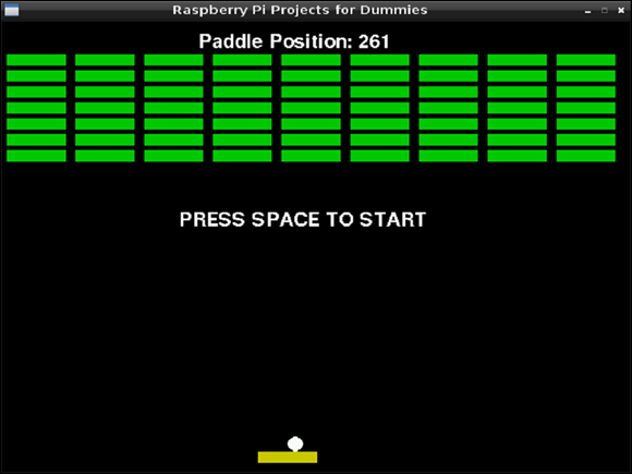
Figure 9-12: The Breakdown game being controlled by a potentiometer connected to the analog-to-digital converter.
Creating an Analog Temperature Sensor
In this section, you use the analog-to-digital converter you construct earlier in this chapter to tell the temperature. The analog temperature sensor you use is a TMP36, shown in Figure 9-13.
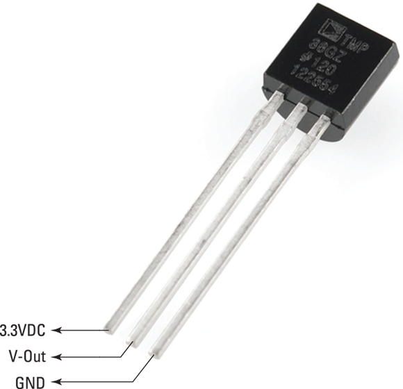
Figure 9-13: TMP36 thermistor.
The TMP36 is a low-voltage, centigrade temperature sensor. It provides an analog voltage output that is linearly proportional to the temperature. It’s very easy to use. Just connect 2.7 to 5.5 VDC, and it produces the analog voltage on the output pin.
In this project, it’s important for your digital converter to produce an accurate reading. Depending on how frequently you want to read the temperature, you can increase the settling time of the low-pass filter of the converter to improve accuracy. The speed of the conversion is probably less important to you than it was with the Breakdown game. The software that you wrote earlier in this chapter provides you with a reading between 0 and 1,023. You can calculate the voltage using the following formula:
Analog Voltage = (Analog-to-Digital Reading ÷ 1,023) × 5
where Analog-to-Digital Reading is the reading from the analog-to-digital converter and 5 is the reference voltage we’re using with the analog-to-digital converter.
The temperature formula for the TMP36 sensor is as follows:
Temperature = (Sensor Reading Millivolts – 500) ÷ 10
A volt is equal to 1,000 millivolts, so for our purposes, we use the following formula:
Temperature = ([Analog Voltage × 1,000] – 500) ÷ 10
For example, if the analog-to-digital converter gives you a reading of 144, the calculation is as follows:
- Analog Voltage = (144 ÷ 1,023) × 5
- Analog Voltage = 0.70381
- Temperature = ([0.70381 × 1,000] – 500) ÷ 10
- Temperature = 20.831°C
Constructing the circuit
Here are the parts you need to build this circuit:
- A TMP36 sensor: This is a wide-range, low-power (between 2.7V and 5.5V) temperature sensor that outputs an analog voltage that is proportional to the ambient temperature.
- A solderless breadboard: A solderless breadboard is a prototyping board where parts and wires can be connected by clipping them into the board. It’s used for prototyping electronics without having to solder parts together.
- Assorted jumper wires for a solderless breadboard: Use male-to-male for breadboard connections and male-to-female for connecting the breadboard to the GPIO pins. Jumper wires usually come in packs of various quantities, colors, and sizes. Any size will do for this project, but shorter male-to-male (10cm) and longer male-to-female (20cm) are best.
As per Figure 9-13, connect pin 1 (left) to 3V, pin 2 to the analog-to-digital converter (refer to “Building an Analog-to-Digital Converter” section of this chapter), and pin 3 (right) to ground.
Writing the software
Listing 9-5 is the Python software for the TMP36 that uses the successive approximation method program built in the “Software for the successive approximation method” section of this chapter.
Listing 9-5: Python Code for the TMP36 Analog Sensor Using an Analog-to-Digital Converter
#!/usr/bin/env python
"""
Raspberry Pi Projects For Dummies: TMP36 thermistor
using successive approximation and an analog-to-
digital converter
for the Raspberry Pi
"""
import os
import sys
import subprocess
import re
output = subprocess.check_output(["~/succ","1"])
s = re.search("Ch0 =s+([0-9a-f]+)", output)
if s:
x = float(s.group(1))
analog_voltage=(x/1023)*5
temperature = ((analog_voltage * 1000) - 500) / 10
fahrenheit = temperature*1.8+32
print "Temperature = " + str(round(temperature,2)) + "C " + str(round(fahrenheit,2)) + "F"
else:
print "Invalid reading"
Run the program and check that the reading is correct:
$ python tmp36.py
Temperature = 19.4C 66.93F
The program prints both Celsius and Fahrenheit temperature values. If your reading is high, make sure that the reference voltage on the analog-to-digital converter is exactly 5V. Use a multimeter to make sure that you’re getting exactly 5V from pin 2 of the Raspberry Pi. When you have an accurate reading, pinch the TMP36 with your fingers and watch the temperature rise as the sensor warms up from your body heat.
Compare the results of the successive approximation method to the ramp and tracking methods by changing the following line of code:
output = subprocess.check_output(["/home/succ","1"])
Change succ in the preceding line of code to ramp for the ramp method and track for the tracking method.
Interfacing with an Analog-to-Digital Microchip
In this section, you use a high-precision analog-to-digital converter that performs the digital conversion external to the Raspberry Pi. The microchip you use is the MCP3008. It performs the analog-to-digital conversion and outputs a digital reading to the Raspberry Pi. The MCP3008 is an 8-channel 10-bit converter and is capable of conversion rates of up to 200 kilo samples per second (ksps), with a conversion time of 10 microseconds.
Figure 9-14 shows the pin allocation of the MCP3008 and how it maps to the GPIO pins on the Raspberry Pi. Use the semicircular indentation on the MCP3008 to orient yourself to the diagram. The eight pins down the left side are eight analog inputs. And the pins down the right side provide the chip with power, ground, a reference voltage, and the various connections required for the serial peripheral interface (SPI). The communication between the Raspberry Pi and MCP3008 is handled by SPI, which is a full duplex serial communication link. The Raspberry Pi supports the SPI protocol and has pins assigned for it on the Raspberry Pi GPIO header.

Figure 9-14: Pin assignment for the MCP3008 and Raspberry Pi GPIO.
In this section, we show you how to interface a temperature sensor and a potentiometer so you can compare the readings you get from the MCP3008 with the analog-to-digital converter you build earlier in this chapter.
Assembling the parts you need
Here are the parts you need:
- An MCP3008: This is a high-precision 10-bit 8-channel analog-to-digital converter. You could also use the MCP3004, which has four analog inputs instead of eight.
- A TMP36: This is a wide-range, low-power (between 2.7V and 5.5V) temperature sensor that outputs an analog voltage that is proportional to the ambient temperature.
- A 10K breadboard trim potentiometer
- A solderless breadboard: A solderless breadboard is a prototyping board where parts and wires can be connected by clipping them into the board. It’s used for prototyping electronics without having to solder parts together.
- Assorted jumper wires for a solderless breadboard: Use male-to-male for breadboard connections and male-to-female for connecting the breadboard to the GPIO pins. Jumper wires usually come in packs of various quantities, colors and sizes. Any size will do for this project, but shorter male-to-male (10cm) and longer male-to-female (20cm) are best.
Constructing the circuit
Construct your circuit as shown in Figure 9-15. Be careful to orient the TMP36 thermistor the right way around (refer to Figure 9-13 for pin assignment). The potentiometer in the diagram uses the middle put as the analog output. The two outer pins of the potentiometer connect to +3.3V and Ground. The temperature sensor is connected to channel 1, and the potentiometer is connected to channel 0 of the MCP3008.
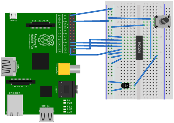
Figure 9-15: How to connect the MCP3008 to your Raspberry Pi GPIO.
Writing the software
In order to enable SPI on the Raspberry Pi, you need to edit the following file and comment out the spi-bcm2708 line as shown in Figure 9-16.
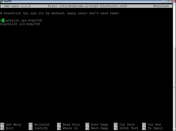
Figure 9-16: Enable SPI by removing it from the blacklist.
From the Raspberry Pi commend line type the following:
sudo nano /etc/modprobe.d/raspi-blacklist.conf
Press Ctrl+X, then press Y, and finally press Enter to save and exit. Then reboot your Raspberry Pi by typing the following:
$ reboot
If you haven’t already installed the WiringPi library, refer to the “Installing WiringPi” sidebar earlier in this chapter. You use the mcp3008 subroutine within WiringPi to interface with the MCP3008 chip.
Listing 9-6: C Code for a Potentiometer and Temperature Sensor Connected to an MCP3008
/*
* mcp3008.c
* Raspberry Pi Projects For Dummies: MCP3008
* Analog-to-Digital Converter
* Potentiometer and temperature sensor
*/
#include <wiringPi.h>
#include <mcp3004.h>
#include <stdio.h>
#include <stdlib.h>
#include <stdint.h>
#define BASE 100
#define SPI_CHAN 0
int main (int argc, char *argv[]){
int tmp,pot, one_reading;
float analog_voltage, temperature, fahrenheit;
if (argc!=2){
  printf ("usage : msp3008 [single_reading 1/0]
");
exit(1);
}
one_reading = atoi(argv[1]);
mcp3004Setup (BASE, SPI_CHAN);
while (1) {
pot = analogRead (BASE+0);
tmp = analogRead (BASE+1);
analog_voltage=((float)tmp/1023)*3.3;
temperature = ((analog_voltage * 1000) - 500) / 10;
fahrenheit = temperature*1.8+32;
  printf ("Ch0 = %d Ch1 = %d Temperature = %2.2fC %2.2fF
",
pot, tmp, temperature, fahrenheit);
if (one_reading) return(0);
}
}
The code obtains an analog reading from channels 0 and 1 and then calculates the temperature based on the analog reading in the tmp variable. For more details regarding the theory behind the TMP36 sensor, please refer to the “Creating an Analog Temperature Sensor” section, earlier in this chapter
.
Compile and run the program from the Raspberry Pi command line as follows:
$ gcc -o ./mcp3008 mcp3008.c -l wiringPi
$ ./mcp3008 0
The program should print to screen something similar to this:
Ch0=92 Ch1=216 Temperature = 19.68C 67.42F
Ch0=92 Ch1=216 Temperature = 19.68C 67.42F
Ch0=92 Ch1=216 Temperature = 19.68C 67.42F
The Ch0 and Ch1 values are the raw readings from the MCP3008 chip. These readings are values in the range 0 to 1,023. The temperature is calculated using the reading from Ch1.
If you created the Breakdown game (refer to “Using a Potentiometer to Control the Breakdown Game,” earlier in this chapter), you can configure the Breakdown game to use the potentiometer reading from the MCP3008. Change the METHOD constant to M as follows:
$ cd /home
$ sudo nano breakdown.py
Edit the METHOD constant as follows:
METHOD = "S"
Exit and save by pressing Ctrl+X, pressing Y, and then pressing Enter.