
Chapter 2
Setting Up Your Tools and Workbench
In This Chapter
![]() Setting up a project-building workspace
Setting up a project-building workspace
![]() Choosing the right tools for the job
Choosing the right tools for the job
![]() Selecting your accessories
Selecting your accessories
![]() Using breadboards and soldering
Using breadboards and soldering
![]() Finding out about Raspberry Pi LEGO projects
Finding out about Raspberry Pi LEGO projects
The first thing you need to do to get started with Raspberry Pi projects is to get your workspace ready. You need a dedicated work area and the right tools so that you can build the projects quickly and easily. In this chapter, we explain how to create a good workspace with the right set of tools for the projects in this book.
The project chapters assume that you have the basic workspace and tools ready to go. After you dive into a project, it can be a drag to interrupt your work to get some basic tool that you’ve overlooked. But if you have most (or all) of the basics of your workspace covered, you won’t have to stop what you’re doing to go get a hand tool or run to the hardware store.
Getting Ready to Build Your Projects
You can start working on Raspberry Pi projects almost anywhere, but it’s best to have a dedicated spot in which to build them. Completing the projects will take some time, so you want to choose a place where you can work comfortably and see what you’re doing. Generally, setting up and taking down unfinished projects is a hassle — it takes more time and can introduce errors if your connections come loose. You can avoid this problem by setting aside a dedicated workspace.
Setting up your workspace
You need a dedicated area where you can build and test your projects — especially the advanced ones in this book, which can take a few hours or more. You have to connect all the components together, provide power, keep the cables and connection wires organized, and do some light fabrication. So, find a spot in your house, apartment, shed, garage, studio, or wherever, where you and your work will be undisturbed and where you can make a bit of a mess. The workspace in Figure 2-1 has all these things covered.
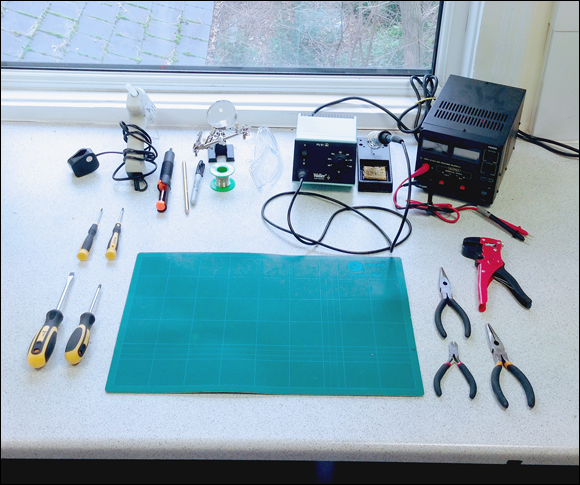
Figure 2-1: A good working environment and some basic tools.
 You don’t want to get interrupted by distractions hunting for parts, or not having the right tools, so it’s important to get the work area ready. In our experience, a good Raspberry Pi workspace has the following:
- A solid workbench or desk
- A comfortable chair
- Dry air and good ventilation (especially for evacuating soldering fumes)
- Plenty of power outlets, ideally at desk height
- Enough room for the screen, keyboard, and mouse, and some extra workbench space for assembly and fabrication
- A nearby network connection or Wi-Fi router
- Shelving and storage for projects you’re working on
- Small boxes and drawers for organizing parts and tools
The environment needs to be comfortable to work in for a long stretch. If it’s too cold or too hot, too noisy, or filled with distractions, it’ll take you longer to complete the work. Make yourself a sort of hideaway where you can stay focused.
Your Raspberry Pi is a fine computer in its own right, but an extra computer is sometimes useful during the project-building process, so it’s good to have room for a desktop or laptop computer on the workbench. Plus, you’ll want to be able to hunt for references online, look up datasheets, and post questions to forums, so a reliable Internet connection is vital.
Keeping an eye on safety
A few of the projects in this book deal with low-voltage electronics. Safety is always a factor when working with electrical circuits. None of these projects works with wall power, but you should always treat electronic projects as if they could have potentially dangerous voltages. If children may roam around your work area, take special precautions to keep them away. Little kids love pulling on cords and cables and could easily drag everything off your desk with one quick tug. A hot soldering iron left unattended could cause severe burns, besides being a fire hazard.
It’s probably best to keep food and drink separate from your workbench. Empty pizza boxes or soda cans may hide critical parts, and you can waste time hunting for things. Accidentally spilled drinks don’t do good things for live circuits.
Assembling Your Tools
You need some basic tools to build several of the projects in this book. The tools basically fall into two categories: electronics tools and physical building and fabrication tools. You can get most or all of these components from electronics retailers such as Radio Shack (in the United States) or Maplin (in the UK). Specialty electronics suppliers on the Internet also stock them and are often cheaper, so hunt around at places like Farnell (www.farnell.com), Newark (www.newark.com), Rapid Electronics (www.rapidonline.com), and RS (www.rs-components.com). Sometimes you can find good deals on Amazon (www.amazon.com) and eBay (www.ebay.com), too.
Electronics tools
Here are the basic electronics tools you’ll want on your shopping list:
- A multimeter: A multimeter is an essential tool for most electronic projects. You use it to perform basic tests to make sure that you have good connections in your electrical circuits. With a multimeter, you can measure the characteristics of an electrical circuit and troubleshoot why something may not be working. A multimeter is also handy for testing and measuring individual electronic components. You should have one on hand for testing and troubleshooting your projects. (See the following section, “Selecting a multimeter,” for more information.)
- A breadboard and jumper wires: Some of the projects in this book involve wiring up electrical components, LEDs, sensors, or actuators to your Raspberry Pi. This can be as simple as one or two wires, but some of the projects have many connections. A breadboard is a simple tool to help you easily make all these electrical connections. You need jumper wires to make connections when you’re using a breadboard. Wires come in solid core and stranded versions (which contain many fine wires). You need solid core jumper wires for working with breadboards.
- A soldering iron: A breadboard is ideal for temporary connections and prototyping, but for some connections you’ll want something more permanent. This is where a soldering iron comes in. You use a soldering iron to make strong, permanent connections between electronic components. If you want to mount buttons onto an enclosure for your project, you’ll probably want to solder wires to the buttons and connect these to your Raspberry Pi. You can even build part of your circuit on a breadboard and use soldered connections for switches or sensors that are located some distance away. (See the upcoming section, “Selecting a soldering iron and accessories,” for more information on what to look for.)
- A power supply: None of the projects in this book requires a desktop power supply, so this is optional. But for general electronics experimenting, you’ll probably want to have a power supply on hand.
Selecting a multimeter
A multimeter is an essential tool for testing, measuring, and diagnosing problems in electronic circuits. You use a multimeter to measure several basic attributes of your circuit, including:
- Continuity: Whether there is a good connection between two points
- Voltage: The measure of potential electromotive force in a circuit
- Current: The measure of the continuous, uniform flow of electrons through an unbroken pathway in an electrical circuit
- Resistance: Opposition to the flow of current within a circuit
With a multimeter, you can also measure the voltage provided by batteries and power supplies, and the characteristics of discrete electronic components, such as resistors, capacitors, diodes, and transistors.
Different models have different features, and the more expensive ones have advanced features you may not need. That said, there are two important features to look for:
- Continuity with audio signal: Checking continuity — making sure that the things you think are connected really are connected — is the task you’ll use your multimeter for most often. You touch the two probes to part of a circuit to see if they’re connected, and the multimeter screen displays a confirmation. With cheap multimeters, you need to hold the probes in place while looking at the screen, which can be annoying if the probes slip off. It’s a pain to check continuity by holding leads on a circuit while you’re also looking at the display. It’s much easier to just poke around and listen for an audio signal. Meters with audio output will beep when you test for good continuity so you don’t have to take your attention away from the circuit. If you can, spend a little more for a multimeter that has this feature.
- Auto-ranging: Inexpensive multimeters require you to estimate the range of measurement and set the dial accordingly. On auto-ranging multimeters, you don’t have to set the dial to select the range of measurement that you’re reading. Auto-ranging is particularly handy and can be worth paying slightly more for.
Older multimeters used a needle and graduated scales for the display, but modern ones use a digital readout. If you don’t already have a multimeter, we recommend getting a digital one, like the one shown in Figure 2-2.
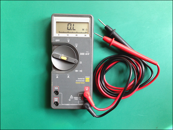
Figure 2-2: A digital multimeter is an essential diagnostic tool.
Selecting a soldering iron and accessories
Many of the projects in this book can be built without soldering anything at all, but you’ll need to do a little bit of soldering for some of the projects, so it’s good to have a soldering iron on hand.
Soldering involves melting solder (a metal alloy that melts at about 700°F) and allowing it to cool, creating a strong, conductive joint. You can solder wires to each other and join wires to components. You can bond wires to circuit prototyping boards such as perfboards and stripboards. Soldering secures components in place, while creating a good electrical connection for a more permanent, longer-lasting project. You can also simply solder certain components (like switches and displays) to wires that lead to your breadboard. That way, you can mount them in a project box. On some projects, you may want to move buttons or switches from the breadboard to the project enclosure, which means you’ll need to solder extension wires on them.
Your soldering iron provides the heat for creating a soldered joint. Many people have the impression that you melt solder onto the parts that you want to connect, but this is actually backward. When soldering, you use a soldering iron to heat up both the solder and the components that are being joined together. When the components are hot enough, the solder will flow onto them, at which point, you remove the tip of the soldering iron and, thus, the heat supply. The solder cools rapidly and, if done correctly, forms a reliable bond.
Figure 2-3 shows a basic array of soldering tools. The key soldering tools you need at your workbench are as follows:
- Soldering iron: Your main soldering tool. Irons can be very inexpensive, but the professional ones can set you back hundreds. If you want to save money, avoid the cheapest ones and aim for a soldering iron that’s at the top end of the low-range options. You’ll need one that supplies at least 30 watts. A soldering iron with an adjustable temperature setting can be useful if you need extra heat for large joints, but it’s not essential.
Solder: A metal alloy you use to create soldered joints. There are both leaded and lead-free varieties. Some purists prefer leaded 60/40 solder (60 percent tin, 40 percent lead), but lead is toxic, so unless you have a particular need for it, we recommend you opt for the lead-free variety, with a rosin core. The rosin core melts and helps to clean the surfaces you’re joining. Solder comes in a variety of diameters measured in standard wire gauge (SWG). For most electronics soldering needs, 18 SWG or 20 SWG diameter is ideal. You can use 22 SWG for detailed work.
Somewhat counterintuitively, as the wire gauge number goes higher, the diameter of the wire gets smaller.Extra soldering tips: Tips do the main work of the iron, directing the heat in the right place. Tips come in a variety of shapes and sizes. For most electronics work, you’ll need a cone-shaped tip rather than a chisel tip. Because they come into contact with molten metal and impurities, tips can degrade over time, so it’s a good idea to get spares.
Different manufacturers have different tip-mounting systems, so buy a couple extra tips when you buy your iron to avoid having to hunt for the right product later.- Soldering stand: A device that holds the wand safely while it’s hot. It may have a sponge for cleaning the tip. Soldering stands are often included with soldering iron kits.
- Cellulose sponge and brass wire sponge: You use these to clean the tip of your iron, which you do while the iron is hot. You can use either a cellulose sponge or a brass wire sponge, depending on your preference. The cellulose sponge can be any garden-variety kitchen sponge from the supermarket dipped in a bit of water and wrung out. Using a moist sponge cools down the tip of the iron, which is something to avoid because your iron will have to work harder to keep the tip at a constant temperature, and contaminants can build up on the tip. The brass wire sponge costs a little more, but it doesn’t cool down the tip of the iron when you’re cleaning it and it doesn’t contaminate the tip. Using brass wire also means that your tip will last longer.
- Desoldering tools: You use these tools to remove unwanted blobs of solder from your work or disconnect wires, traces, or components that you may have soldered together by accident. You can find both desoldering wick and soldering suckers. A soldering sucker is a spring-loaded pen that you can use to suck liquefied solder away from your work piece. Desoldering wick is simply braided flat copper ribbon, which you press against your work while heating it. Capillary action draws the liquefied solder onto the braid and away from your work. We tend to prefer wick, which is cheaper and usually more effective.
- Tip-cleaning paste: Even with careful use, your tip may develop an oxidation coating, especially if you don’t clean it regularly. This makes it very difficult to coat the tip and control the way your solder flows. Cleaning paste can help to remove oxidation and debris.

Figure 2-3: An entry-level soldering iron and essential accessories.
Physical building and fabrication tools
You also need some basic tools for light fabrication. Not all these tools are essential, but often the one tool you don’t have is the one you need so you may want to stock up. Figure 2-4 shows some of the essential tools. We’ve listed these roughly in order of importance, from most to least:
- A selection of precision screwdrivers: Both flathead and Phillips-head screwdrivers are essential.
- Helping hands: This is a small clamp with two alligator clips to hold your work piece; it often comes with an integrated magnifying glass. This tool is essential for gripping objects you’re working on — unless you have three arms.
- Wire strippers: You use these for cutting and stripping the insulation off of wires. They come in several different styles. Splurge a little here — if they’re too cheap, they’ll produce poor results and be frustrating to use.
- Angled side cutters: You use these for clipping component leads and cutting wires.
- Needle-nose pliers: Use these for holding fine objects. You should have both small and large ones on hand.
- A task light with magnifier: Use these to provide direct illumination and to make it easier to see fine work. Get one with a spring arm so that you can place it right over your work, if necessary.
- A box cutter/carpet knife with replaceable blades: Use this for cutting sturdier materials.
- A cutting mat: You need this to protect your work surface.
- A Sharpie and a pencil: Use these for making cutting marks and permanent marks. No workbench is complete without a Sharpie!
- Hand drill and small hand saw (not shown): For small projects, you can probably use inexpensive hand tools, which you should be able to get at your local hardware store. Power tools will also work, but they’re generally more expensive.
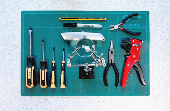
Figure 2-4: Some essential light fabrication tools.
Using Your Tools Safely and Effectively
When you’ve assembled all the tools and set up your workspace, you’ll probably be eager to dive right in! But before you do, take a few minutes to read the information in this section so you don’t hurt yourself or those around you.
Working with electricity
 In working with electronics, safety is critical. You should take basic precautions to protect yourself. None of the projects in this book involves connecting directly to the wall power, but you should use precautions anyway and develop good safety habits. Even though you may only be working with low DC voltages, it’s a good idea to follow some basic safety rules when working with all electronic projects:
- Don’t touch metal contacts or leads in a live circuit.
- Don’t alter a live circuit. Always disconnect power before removing or adding components to your Raspberry Pi or breadboard.
- Always test with one hand tied behind you back. Well, at least one hand not on the work piece. If enough stray current flows between both your hands, and across your heart, it can cause arrhythmia. That’s not likely at the low DC voltages we’re working with here, but it’s best to be safe and get into the habit.
- Sounds crazy, but don’t work barefoot. Maximize the resistance between you and the floor by wearing good, rubber-soled shoes. A puddle of water is a great conductor, and you don’t want to be in one, if something goes wrong.
- Wear an antistatic wrist strap. Your Raspberry Pi is a tough little computer, and if it’s in an enclosure it should be well protected. However, it and other components are sensitive to wayward voltages, including static electricity. Several thousand volts of static electricity can build up on you, and you may not even know it, especially on carpeted floors. If it does and you touch your hardware, you can fry it in an instant. An inexpensive antistatic wrist strap will guard against unexpected sparks by connecting you at all times to ground, which diverts any electrical charge from building up on your body.
- When fabricating or soldering, wear light, comfortable safety glasses. Wire offcuts can fly around the room when they’re clipped, and hot solder can sometimes spit and splutter. You don’t want any molten metal heading for your eyes.
Laying the foundation for your electronics work
To quickly and easily connect your project circuits, start out by using a breadboard. All the projects involving electronic circuits in this book can be built on a breadboard. After testing on a breadboard, you can either put your Raspberry Pi and your breadboard inside an enclosure or build your circuit permanently on a stripboard or perfboard, which requires a bit of soldering.
Breadboards
A breadboard is a small block of plastic with lots of rows of holes into which you can insert jumper wires and electronic components. Underneath the holes are tiny metal strips forming springs, which grasp wires and the legs of components that are inserted into the holes. Because the springs are metal, if you connect wires or components to the same springs, they’re electrically connected together.
Because breadboards use springs to hold the wires, you should always use solid core wire on them. Stranded wire (which is composed of multiple tiny wires) will get scrunched by the springs when you try to push them into the holes on the breadboard. It’s a big pain to use stranded wire, so save yourself the trouble.
In the main work area on the breadboard, the holes are typically organized into rows of five and grouped into two columns. There is usually a trough between the two columns of holes, which allows you to insert an integrated circuit (IC) into the breadboard so that each of its legs is served by four adjacent holes.
Many breadboards have columns of holes running the full length of either side of the board. These holes aren’t electrically connected to the main work area, and they’re often labeled + (positive) and – (negative or “ground”) and may be color coded. You use these as “rails” for power and ground. You’ll often want to connect components to power or ground, so you usually need lots of connections to them.
Breadboards come in various sizes, from small (with 400 contact points) to large (with 830 points or more). You’ll want to have at least a small one on hand for testing. If you run out of room, you can connect two breadboards using the notches and fingers on the sides of the boards. But be warned: There’s no standard for these, so they usually need to be from the same manufacturer in order for you to connect them.
Stripboards and perfboards
Stripboards and perfboards are similar to breadboards — they have lots of holes to connect things together — but they’re designed for permanent connections that are soldered in place. Stripboards are coated with adhesive strips of conductive copper that run underneath the holes. Electronic components are soldered to the strips of copper, providing an electrical connection and a strong physical bond. Perfboards have metallic pads that surround each individual hole, into which you can solder parts and which you can solder together to create electrical circuits.
Stripboards and perfboards come in a huge range of shapes and sizes (see Figure 2-5), so if and when you’re ready to go for a more permanent solution, shop around for the size and type you need.

Figure 2-5: Mini and full-size breadboards and a piece of stripboard.
Prototyping boards
A number of manufacturers offer a printed circuit board that has a prototyping area for soldering electrical components, plus a multi-pin jack that you connect to the GPIO socket on your Raspberry Pi. This makes it easy to build circuits and experiment. Our favorite is the Humble Pi prototyping board, available from Ciseco (http://shop.ciseco.co.uk). If you’re outside the UK, you should be able to find it from other online retailers, like Amazon (www.amazon.com).
This board stacks right on top of your Raspberry Pi to make a little sandwich, as shown in Figure 2-6. It comes in a kit form and is easy to put together. You simply solder the GPIO socket to the board. If you aren’t confident with your soldering skills, this is a good kit to practice with, because it’s difficult to damage it by making soldering mistakes.

Photograph courtesy of Humble Pi
Figure 2-6: A Humble Pi prototyping board stacked on top of a Raspberry Pi.
Project boxes and housings
Many of the projects in this book are built on a breadboard because it’s a fast and easy way to get going. If you want to protect the project, you can transfer it to a dedicated enclosure.
Potential project housings are everywhere, and almost anything that can be used as a small box will do. Electronics suppliers usually stock a range of generic enclosures, in both metal and plastic. When selecting one of these, make sure that you have the correct tools to fabricate your housing. If you’re going to mount switches, buttons, or a display on the project box, you’ll need to be able to cut through the material cleanly. It’s really difficult to drill a hole into thick materials and metals without the right saws, drills, and bits, so make sure to select a housing that you can work with.
Another source of project enclosures is one of the new and popular laser cutting or 3D printing services, such as Pololu Robotics & Electronics (www.pololu.com), Ponoko (www.ponoko.com), and Thingiverse (www.thingiverse.com). You send off your design to them, and they’ll ship you your finished custom laser-cut design. Many of these companies also have templates you can download for boxes and enclosures.
Soldering safely
When you’re first trying your hand at soldering, it’s a good idea to practice on some throwaway stuff that you won’t mind messing up. It takes a while to get the hang of soldering — how long it takes to heat up the solder, how to flow it onto components, and how to make a good solder joint. You can use a piece of stripboard to do a few test connections, without worrying about damaging things on your project.
When soldering, follow these basic steps:
- Secure the main piece of the work (your stripboard, circuit board, or other components) to your worktable, or use a pair of helping hands to hold the piece.
- Unwind a bit of solder from your spool.
- Hold the iron as you would a pencil and place it in contact with the elements that you’ll be soldering.
After a moment, press the end of the unwound bit of solder against the surfaces that you want to join.
This should be right near where the tip of the iron is heating up the components. The solder should begin to melt and coat the components.
- After the surfaces are well coated, remove the solder you’re feeding into the joint.
- Remove the iron and wait until the surfaces are cool.
Examine the joint.
The joint should be shiny. On a stripboard or perfboard, the joint should form a volcano shape around the wire that you’re soldering and should be mechanically secure. It shouldn’t wiggle around if you press against it.
Try not to take a long time to solder the joint — ideally, only a few seconds. Excessive heat can damage the components, especially with sensitive components such as transistors and ICs. You may not even know they’re damaged until you realize that your project isn’t working and you have to track down the problem!
Practice soldering on extra bits of wire or on resistors, because they’re cheap and easy to work with and it doesn’t matter if you overheat them — you can just throw them away after you’re finished practicing. If you have any electronics board lying around, you can practice your desoldering skills, too, using a desoldering wick (see “Selecting a soldering iron and accessories,” earlier in this chapter). Try to remove parts from the boards. You’ll quickly see why it’s a good idea to get your soldering skills up to speed — taking things off a circuit board is a lot harder than soldering things on!
Figure 2-7 shows an example of soldering components to a perfboard. When you’re soldering, you apply the iron to the components and then flow the solder into the heated area. You need to ensure that the components are hot enough for the solder to adhere to them. You don’t heat the solder and drip it onto the parts. The solder will liquefy around the components and coat them. When they’re coated, remove the solder and the iron, and allow the parts to cool. The result should be a strong connection that you can’t pull apart.

Figure 2-7: Soldering components to a perfboard or stripboard.
Here are some soldering tips to keep in mind:
- Make sure your parts and surfaces are clean. In particular, make sure you clean your soldering iron tip using a damp sponge.
- When you first use your soldering iron, and periodically thereafter, coat the tip of your iron with a little solder — just enough to make it shiny. This is called tinning and will make it easier to solder your connections.
- Don’t overheat parts. You should heat the components just long enough to make a good connection. If you apply too much heat, some sensitive components could be damaged.
- Safety first. Make sure you aren’t soldering over your hands or another part of your body. If the solder drops off your work, you could be burned. Remember: Make sure to wear safety goggles — burning solder can sometimes spit and fly in unexpected directions.
- Be careful not to breathe in the soldering fumes. Work in a well-ventilated area.
Getting Ready to Build Raspberry Pi LEGO Projects
Chapters 13 through 15 use the LEGO MINDSTORMS system. LEGO has been a popular toy for decades. Since the 1980s, it has produced a series of products that can interface with a computer and be programmatically controlled. Recently, the company has produced products geared toward robotics experimentation called MINDSTORMS. You can connect your Raspberry Pi to this latest range of products. We use the MINDSTORMS system to quickly and easily build complex projects. The modular building system makes the physical work of rigging up a robot or computer-controlled object very easy.
The core of the MINDSTORMS system is the MINDSTORMS Intelligent Brick, which contains the processor and memory required to do programmatic control. You send programs to the Intelligent Brick, which can then execute complex instructions, such as reading data from sensors or controlling motor drive systems. The brick has several ports for input and output, along with a display that you can program, as well as a number of buttons that can be used for input that you can read with your Raspberry Pi.
Several kinds of MINDSTORMS systems have been developed over the years, and the latest version is the MINDSTORMS EV3. If you plan on trying out some of the LEGO projects, you’ll need to get the most recent version. You can buy the LEGO MINDSTORMS EV3 kit, which contains both the control brick and a bunch of extras to build several projects. This kit is pretty expensive (around $350), so if you want to save a little, you can just buy the control brick, which is about half the cost of the full kit. You can sometimes find the brick for sale on eBay at a lower price.
In Chapter 13, we provide more information on the EV3 system and using it with your Raspberry Pi.