
Chapter 7
The Light Fantastic
In This Chapter
![]() Building an illuminated button pad
Building an illuminated button pad
![]() Making your first PCB hack
Making your first PCB hack
![]() Seeing stunning multicolor effects
Seeing stunning multicolor effects
![]() Exploring alternate color models
Exploring alternate color models
![]() Learning how a keyboard scanning matrix works
Learning how a keyboard scanning matrix works
This project is about producing a universal 4-x-4 illuminated switch matrix. Why? Because it’s a great base for so many projects with physical interfaces. This chapter shows you how to build and test it, as well as produce a light show with it. In Chapter 8, we show you how to make four games using this interface, as well as a whole host of other uses you can put this to. A photograph of the final project is shown in Figure 7-1.
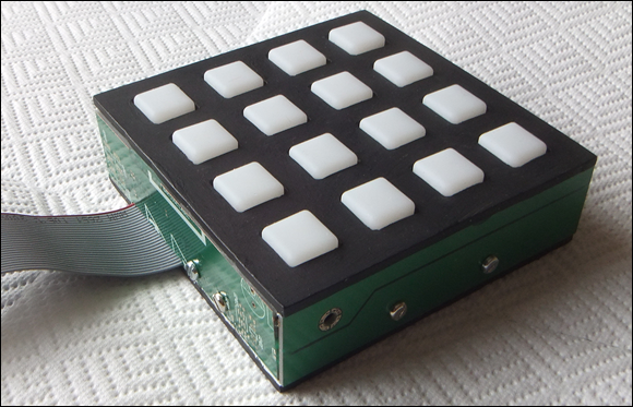
Figure 7-1: The finished Light Fantastic.
Introducing the Light Fantastic
This interface can be described as an undedicated controller. It consists of 16 push switches, each illuminated by an RGB LED. In Chapter 6, you see how you can use LEDs and, in particular, a long strip of LEDs, all controlled by a single Raspberry Pi pin. Those LEDs in the strip are also available in a normal 5mm LED package, and they’re used to create this project.
Before the availability of WS2812b LEDs, constructing a project like this was complex. The multiplexing required meant that it couldn’t be done with a Raspberry Pi, because of the time-stealing nature of the Linux core. But with this revolutionary LED, this project is comparatively easy.
There are many ways to build this project, but the one we show you here is simple because it makes use of a readymade printed circuit board. This printed circuit board wasn’t designed to use the WS2812b LEDs; instead, it was designed to use the more conventional common anode or common cathode RGB LEDs. We show you how to hack the printed circuit board in order to take this new component.
Here are the components you need:
- Button Pad 4x4–LED Compatible (
www.sparkfun.com/products/7835) - Button Pad 4x4–Breakout PCB (
www.sparkfun.com/products/8033) - 16 WS2812b 5mm LEDs
- 16 1N4148 or similar diodes
- 16 0.1uF ceramic capacitors
- 470R resistor
- 0.5 meter of 26-way ribbon cable
- 26-way IDC socket (or 40-way if you’re using a Raspberry Pi Model B+)
- Four 15mm hexagonal M3 tapped pillars or spacers
- 13 M3 10mm pan-head screws
- 12 M3 10mm countersunk screws
- 21 M3 hex nuts
For the enclosure we used:
- Scrap PCB boards for the side (you can also use ABS or thin plywood)
- 3mm ABS sheet for the base, top cover, and light baffle
- 200mm of 7mm (or so) angle aluminum
The Circuit
There are two parts to the circuit of the Light Fantastic: One is for the switches and is called a switch matrix; the other is for the switch illuminating LED. We start with the LEDs.
LEDs
This is a very simple circuit. It consists of a single string of 16 WS2812b LEDs, chained together, with the data output of one going into the data input of the next. Each LED has a connection to a 5V and ground of a power supply. In most cases, this can be driven directly off the general-purpose input/output (GPIO) pins of the Raspberry Pi, as long as the Pi’s power supply can handle an extra amp of current. The only other component is a 0.1uF ceramic decoupling capacitor across the power supply of each LED. The circuit is shown in Figure 7-2.

Figure 7-2: The LED schematic.
Note: Figure 7-2 shows just 4 of the 16 LEDs for clarity; the other 12 LEDs are wired just the same between the broken doted lines.
Switches
The switch circuit is a bit more complex. It’s based around the 4 x 4 silicone button pad sold by SparkFun Electronics, composed of 16 switch covers that have a ring of conduction carbon at the base. The idea is that it fits over a dual ring and spoke track on a PCB; when the cover is pressed, the conducting ring makes contact and shorts out the inner and outer PCB track rings, completing a circuit.
In theory, you could just wire up each switch to a separate GPIO pin, but when you use a lot of keys, you use a lot of inputs, so switches are often arranged in a matrix, as shown in Figure 7-3. In a matrix, there are rows of switch inputs feeding into column outputs. Each switch is isolated with a diode. This component lets the electric current flow only one way; it’s important to stop the production of phantom key presses when more than one switch is pressed at once. You can see that although there are 16 switches, only 8 GPIO pins are used. In general for a square matrix, the number of switches you can have is the square of half the number of GPIO pins you use. As you use more GPIO pins, the saving becomes greater.

Figure 7-3: A switch matrix.
The price you pay for this efficiency in hardware is that you need to be clever with the software. Basically, the software scans the matrix. It puts one row line high and the others low. Then it looks at each column input in turn, and if an input is found with a logic 1 on it, you know what key is being pressed on that first row. If nothing is found, then that row is made to output a 0 and the next row is set high. Then the inputs are scanned again. This process is repeated until the whole matrix has been scanned. Suppose switch SW9 is pressed. Only when Row 3 is high will there be a high on Column 2.
 Here’s a small trick to save time seeing if any key is being pressed: Put all the rows high and then if you see a logic high on any column, you know that some key is being pressed. Although this isn’t the only way to read a keypad matrix like this one, it’s by far the most common and is the method used on the board we’re going to hack.
The PCB
In addition to reading switches in a matrix, you can light LEDs in a similar manner, and that’s what the board you’re going to hack was originally designed to do. In each row, all the red LEDs are connected together, as are the green and blue components of the RGB LEDs. This is shown in Figure 7-4, along with the pin out of the RGB LEDs used. Also shown are the connector numbers for the rows and columns. Note the switch matrix circuit in addition to the LED circuit on the board. The switch row inputs are marked as S on the connector pads labeled JP.

Figure 7-4: The original LED matrix circuit.
To convert this into a circuit suitable for the WS2812b LEDs, you need to cut some tracks and add some links in order to convert it into the circuit shown in Figure 7-5. Note how similar it is. What was the blue LED connection on the original board will now be the positive 5V power line. For each row, the green connection is the data input to the first LED, and the red connection is the output from the last LED in the row. Each LED has its data output linked to the data input of the next LED in the row with a wire link.

Figure 7-5: The modified LED circuit.
So, first, you need to make 25 cuts in the tracks of the PCB. The trick is making the correct 25 cuts (see the X’s in Figure 7-6). These cuts should be done with a sharp knife or scalpel. Make two cuts in the track close to each other, and then use the blade to remove the small section of track between the two cuts.

Figure 7-6: PCB track cuts.
The only tricky cut is the one on the data output of the first LED on row 1, next to the label Switch 1. This must be between the LED and the track going off to the connector. This is shown in detail in Figure 7-7.
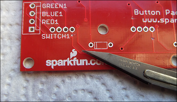
Figure 7-7: Close-up of the bottom-left cut.
Construction
The next step is to solder in all the diodes, which are marked on the board as rectangles with a line at one end. Make sure this line coincides with the line marked on the diode itself.
Now, normally you would insert the diode and solder the other side of the board. However, in this board, the silicone rubber switches will be placed on this track side of the board, so you want as little height on the joints on this side as possible. The technique we used was to fit the diode, and then trim off the lead on the track side flush with the level of the board with a pair of side cutters. Then solder from the component side, letting the solder be sucked down into the hole by capillary action. Be careful not to put too much solder on the joint because you’ll get a dome on the wiring side. The silicone rubber can take some distortion, but try to keep it to a minimum. Figure 7-8 shows the three steps in mounting the diodes.

Figure 7-8: Soldering the diodes and track-side wires.
At the next stage, you add the LEDs, pushing them through the other side of the board to the diodes and bending the legs so that the LEDs lie as close as possible to the board. Notice that there’s a very subtle flat on the side of the LED that marks the data out connection. The data out and the ground connections are also longer than the other two pins. It’s critical that the LEDs are put in the board the right way around. You’ll see an exaggerated flat on one side of the legend where the LEDs are to be inserted, as shown in Figure 7-9.
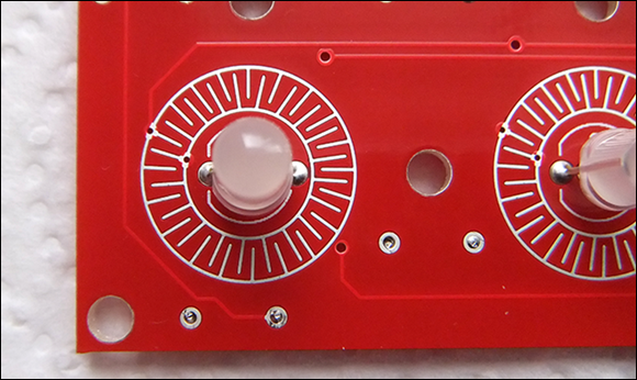
Figure 7-9: The mounting of the LEDs.
Notice the holes showing in Figure 7-9 with the component wires soldered from the track side and the solder filling the hole but not seeping through. Also, notice the two circles with interleaving spokes that surround the LEDs. These are the two contacts of the switch; the conducting rubber ring on the silicone cover makes contact between the inner and outer ring when the switch is pressed. Keep your fingers off these rings or at least wipe them down with a grease solvent before you fit the silicone cover.
Now that the LEDs are in place, you can wire up each row of LEDs so that the data out of one LED goes into the data in of the next. We used some thin insulated wire to do this. There are three links on each of the four rows.
Finally, you need to solder a ceramic capacitor across the middle two wires of the LEDs. These wires are decoupling capacitors and ensure a smooth power supply for each controller chip in the LEDs. We used a small surface mount capacitor and held it close with fine tweezers while we soldered it onto the pins. If you like, you can use small leaded capacitors — just make sure you bend the leads so that they’re as short as possible when soldered up. A photograph of this is shown in Figure 7-10.
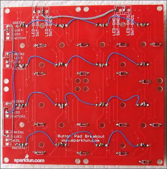
Figure 7-10: Linking up the LEDs.
Now the rows and columns can be commoned up to complete the circuit. Figure 7-11 shows a diagram of these, as well as where they should be connected to the Raspberry Pi’s GPIO pins.

Figure 7-11: Linking up the board connectors.
Connecting to the Raspberry Pi
We decided to use a flying lead from the Light Fantastic board to the Raspberry Pi through a ribbon cable. This allows you to easily attach and detach it. If you have a Raspberry Pi Model B+, you’ll need a 40-way IDC connector; otherwise, you need a 26-way one. Either way, you need about half a yard of 26-way ribbon cable; clamp it to the connector, ensuring that the red wire on the cable is pierced by the connector marked with a triangle, as shown in Figure 7-12. Now squeeze it up in the vice and add any strain relief clamp that came with the connector. The red wire is now pin 1 on the GPIO connector and will be the wire in the ribbon connector closest to the edge of the Raspberry Pi board when you plug it in.

Figure 7-12: Clamping up one end of the ribbon cable.
Having fitted the connector at one end, you can proceed to wire up the other end to the Light Fantastic board; the connections are shown in Figure 7-13. Strip back the individual wires and cut short those that aren’t used. Connect them to the back of the PCB in Figure 7-11. Note the two 5V and two ground connections — wire them both up to reduce any resistance from the connectors. If you don’t have a spare amp in your Pi’s power supply, connect an external 5V supply to the board and don’t connect the 5V on the ribbon cable. When we were finished, we used a double-sided foam pad to stick the ribbon cable to the PCB and stop any mechanical strain from being put on the individual joints.
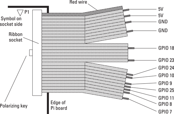
Figure 7-13: The flying lead to the Raspberry Pi.
To finish it off, we put the silicone cover over the LEDs. We fastened it to the PCB with a nut and bolt in the center and middle positions. Don’t tighten the nuts too tight, or the silicone will distort. Finally, we attached a 15mm M3 tapped pillar to each corner of the board so that it stood up on the desk while we tested it.
At this point, the electronic construction is complete, and you can use the project just as it is. However, the project looks much better if you surround it with a box. Also, the colors of the LEDs look so much stronger with a black background, and putting light baffles between the keys stop colors from interfering with each other. We describe one way of doing this in the next section, but if you’re making this, you may want to skip to the testing stage to see if it works before committing to making the box.
Boxing the Light Fantastic
The project looks much better if it’s finished off by putting it in a box. Not only does it look neater, but there is much less glare and the buttons’ colors are better defined. The trickiest part about putting a box around it is making the top bezel. Although you can buy four 2 x 2 bezels for the switch cover, they’re quite expensive, so we decided to make our own. It would’ve been simple to laser-cut some thin plywood, but we didn’t have access to a laser cutter. If you do have access to one, there is a PDF on the book’s website (www.dummies.com/go/raspberrypiprojects) that contains the cutting file.
We used this file to print out the size and position of the 16 square holes and spray-glue mounted it onto some 3mm-thick ABS plastic sheet. Then we used a drill to rough out the holes and a file to give them as neat an edge as we could. It took us about four hours to do this, but a file and a drill is all you need. The only file we had that fit the square holes was a triangular one. Figure 7-14 shows our progress partway through the process.
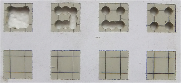
Figure 7-14: Cutting out the top bezel.
The final fitting process involves carefully enlarging the holes one at a time and testing that the button tops slip snugly over the top.
Don’t be too worried about the straightness of the edges to the holes. Visually, any small imperfections are masked by the contrast of the two parts, and it looked a lot more precise than it actually was.
We made the base from exactly the same template as the top, only we didn’t need to cut out the holes for the switches.
You can make the sides of the box from thin plywood if you like, but we used some scrap fiberglass PCB material, which is strong and thin and machines easily (although it will blunt your tools faster). We think it gives the box a “geek tech” feel. We used strips 26mm wide so that the button tops protruded just 2mm above the top bezel. These were mounted on the base by some 50mm lengths of angle aluminum held in place by two pan-head screws and nuts (see Figure 7-15). The right side had this bracket offset so that the ribbon cable could come out of the side; a small recess in the side was cut in with a file to allow the ribbon cable to go underneath.

Figure 7-15: The side brackets.
We applied a little epoxy to fix the nuts to the brackets so they could be fastened without having access to the inside of the box. On the underside of the top bezel, we fitted some strips of the same ABS plastic we used for the top to shield the lit buttons from each other. They were held in place by model airplane glue (see Figure 7-16). In the central strip, we put a small notch in the center and each end to clear the head of the rubber key fixing screws. Then we carefully painted the top bezel a flat matte black. If we had used plywood for the sides, we would’ve painted them as well at this stage.

Figure 7-16: Light baffles on the underside of the top.
In theory, the next step is simple: Drill four holes in the base to take the pillars of the PCB assembly. In practice, though, you don’t know exactly where to drill them and still have the top bezel square. So, we removed the side panel with the ribbon cable slot, put the bezel on the buttons, and aligned everything nice and square. Then we put some hot glue around the base of the two pillars; when it had set, we disassembled the sides and unscrewed those pillars from the PCB. This left just the base with two pillars glued to it in exactly the right place. Then we took a 2.2mm drill (a 2mm one will do if you haven’t got a 2.2mm) and drilled through the pillars into the base. Then we picked off the pillars and the hot glue and drilled out the hole to 3mm. This meant that the two holes were in exactly the right place. So, we assembled it again with screws through the base into the two pillars — only this time, we left the opposite side off and repeated the glue and drill trick to get the other two pillars in exactly the right place.
Finally, we assembled the box again, left both sides off, and tacked the top bezel to the two remaining sides at the corners, again with hot glue. Then we removed the two sides and the top bezel, now attached to each other, and put a heavy glue fillet around the inside of the sides and top.
Make sure you leave a small unglued area for the other two sides to fit in.
Bringing It All to Life
Now you need to write some software to read the switches and light the LEDs. If you’ve done the project in Chapter 6, you’ve installed the NeoPixel Library; if not, turn back to Chapter 6 to see how that’s installed.
Because both the NeoPixel library and the reading of switches require access to the GPIO, you need to be in root mode, so open IDLE with gksudo idle from the command line. Then type in the code in Listing 7-1 to test them both.
Listing 7-1: Switch and Lights Test
# NeoPixel Light Fantastic
# Switch & lights test
# Author: Mike Cook
import time, random
import wiringpi2 as io
from neopixel import *
print"if program quits here start IDLE with 'gksudo idle' from command line"
io.wiringPiSetupGpio()
print"OK no crash" ; print" "
pinList = [9,24,10,23,7,8,11,25] # pins for keyboard
# LED strip configuration:
LED_COUNT = 16 # Number of LED pixels.
LED_PIN = 18 # GPIO pin connected to the pixels
LED_FREQ_HZ = 800000 # LED signal frequency in hertz
LED_DMA = 5 # DMA channel to use for generating signal
LED_INVERT = False # no need to invert on the Light Fantastic
strip = Adafruit_NeoPixel(LED_COUNT, LED_PIN, LED_FREQ_HZ, LED_DMA, LED_INVERT)
def main():
initGPIO()
strip.begin()
print"Keyboard to LED test - Ctrl C to quit"
print"pressing key will light up the LED"
wipe() ; key = 1
while True:
while keyPressed() == False :
pass
newKey = getKey()
if newKey != -1 :
key = newKey
wipe()
while keyPressed(): # wait for release
pass
strip.setPixelColor(key, Color(255, 0, 0))
x = key % 4
y = key / 4
print"key ",key," X=",x," Y=",y
strip.show()
def initGPIO():
for pin in range (0,4):
io.pinMode(pinList[pin],0)
io.pullUpDnControl(pinList[pin],1) # input enable pull down
for pin in range(4,8):
io.pinMode(pinList[pin],1) # output
io.digitalWrite(pinList[pin],1) # all high
def keyPressed(): #is a key being pressed>?
pressed = False
for pin in range(0,4):
if io.digitalRead(pinList[pin]):
pressed = True
return pressed
def getKey():
key =-1 # -1 = no key
for outPin in range(4,8):
io.digitalWrite(pinList[outPin],0) # all low
for outPin in range(4,8):
io.digitalWrite(pinList[outPin],1)
for read in range(0,4):
if io.digitalRead(pinList[read]):
key = ((outPin-4) * 4) + read
io.digitalWrite(pinList[outPin],0) #remove active row
for outPin in range(4,8):
io.digitalWrite(pinList[outPin],1) # leave all high
return key
def wipe():
for i in range(0,strip.numPixels()):
strip.setPixelColor(i, Color(0, 0, 0))
strip.show()
# Main program logic follows:
if __name__ == '__main__':
main()
The setting up of the NeoPixel library should be familiar to you if you read Chapter 6; the difference here is that there are only 16 LEDs. The pinList list is the GPIO pin numbers used for the switch matrix. The first four are the input columns, and the last four are the output rows of the matrix. These pins are initialized in the initGPIO function. Note that the inputs have their pull-down resistors activated so they’ll read a steady zero in the event of no key being pressed. The row outputs are all set high in preparation for the next function, keyPressed.
This function’s job is just to return a True if a key is being held down and a False if it is not. It assumes that all the rows are high, which they will be after that first function. It does this by initializing a variable pressed to be False and then looking at each column in turn and setting this variable to True if a logic 1 is seen on any of the input columns.
Although sometimes you just want any key indication, when the program knows a key is being held down, it’s normal to want to know which key. This is where the getKey function comes in. It starts off by setting all the row outputs to 0. Then a for loop will put them high one at a time. Inside this for loop is another for loop, which reads each column in turn. If a logic 1 is detected, it sets a variable called key to be the index of this inner loop plus four times the index of the outer loop — in other words, the key number. Before the function exits, the code sets all the row outputs high (to a logic 1) for the next time the keyPressed function is called.
The wipe function simply sets each pixel color to black. So, all that remains is the main function. This calls the functions that initializes the key’s GPIO pins and the LEDs and sets them all to black. Then it enters an infinite loop where it waits until there is a key press; then it goes off to read the key, wipes the LEDs, and waits for the key to be released. Then the LED corresponding to the key being pressed is set to green and both the key number and its x- and y-coordinates are printed out before the pixel buffer is transferred to the LEDs with the strip.show function call.
Now, you may have spotted that we said the LED to light up would be green, but we set this up with the line strip.setPixelColor(key, Color(255, 0, 0)), which, as you may expect from Chapter 6, would be red. It turns out, for no explained reason we can tell, that the 5mm version of the WS2812b has the red and green data packets swapped over when compared to the surface mount package used in the LED strips and rings. So, you need to swap red and green in the function call to get the color you expect.
A bit of a show
Now that we have everything working, we finish off this chapter with a bit of a light show. Basically, it consists of eight sequences that you can use to turn on the LEDs and a way of generating a random color. The LEDs turn on one at a time with a small interval between them and then rapidly turn off. This repeats until another key is pressed — the keys are looked at only after the sequence ends, so you have to press a key and hold it until all the lights are off before you can change the sequence.
For each sequence, there are two ways of generating the color: one changing every four steps in the sequence and the other changing every step. The top eight keys evoke the first changing method; the second eight keys evoke the second step.
The way colors are generated here is worth a mention. If you want to generate a random color, setting the red, green, and blue components may seem to be what you would want to do, but that’s not the case. Although it will produce random colors, they’ll mostly turn out to be fairly washed out.
What you need is another way of representing color. The red, green, blue (RGB) method is often called a color cube, with each color component representing a coordinate in a cubic space. There are several other color models as well; one popular one is known as hue, saturation, value (HSV). The hue is what you would describe as the basic color; the saturation is how intense that color is; and the value is the brightness of the color.
 Saturation and value are quite different, although they sound like they may be the same thing. If you were to deal with mixing paints, the hue would be the basic pigment, and the saturation would depend on how much white you added. For a fully saturated color, you would add no white, and for a pale, washed-out color, you would add a lot. Similarly, the value would be how much black paint you added — no black for the full brightness and a lot for a very dim, dark color. This representation of a color is often known as hex cone space because the space bounded by these coordinates represents a hexagonal cone. We use a simple function to generate a full-brightness, fully saturated color that is very useful for generating a reasonable set of random colors.
The code for the light show is shown in Listing 7-2. Because this has the key reading functions identical to those in Listing 7-1, to save space they aren’t printed here — just copy the function from the previous listing you typed.
Listing 7-2: The Light Fantastic Light Show
# NeoPixel Light Fantastic
# Light sequence
# Author: Mike Cook
import time, random
import wiringpi2 as io
from neopixel import *
print"if program quits here start IDLE with 'gksudo idle' from command line"
io.wiringPiSetupGpio()
print"OK no crash" ; print" "
pinList = [9,24,10,23,7,8,11,25] # pins for keyboard
order =[ [ 0,1,2,3,7,6,5,4,8,9,10,11,15,14,13,12 ],
[ 0,4,1,5,8,2,12,3,9,6,13,7,10,14,11,15 ],
[ 9,10,6,5,4,8,12,13,14,15,11,7,3,2,1,0 ],
[ 12,9,6,3,0,5,10,15,4,8,13,14,11,7,2,1 ],
[ 12,8,4,0,1,2,3,7,11,15,14,13,9,6,10,5 ],
[ 0,8,1,9,2,10,3,11,7,15,6,14,5,13,4,12 ],
[ 12,3,15,0,9,6,10,5,8,7,4,11,13,2,14,1 ],
[ 12,15,0,3,8,11,4,7,13,1,14,2,9,6,5,10 ], ]
strip = Adafruit_NeoPixel(16,18,800000,5,False)
def main():
initGPIO()
strip.begin()
print"Use the light fantastic keyboard to:-"
wipe() ; key = 1
print"press key for demo ",
print"press and hold until lights go out to change demo"
while keyPressed() == False :
pass
while True:
newKey = getKey()
if newKey != 16 :
print "New sequence ",newKey
key = newKey
wipe()
while keyPressed(): # wait for release
pass
if key < 8:
fill(key, True)
elif key < 16:
fill(key-8, False)
def initGPIO():
    # see Listing
7-1
 for this function
def keyPressed():
    # see Listing
7-1
 for this function
def getKey():
    # see Listing
7-1
 for this function
def wipe():
    # see Listing
7-1
 for this function
def colorH(angle): # Color returned H=angle, S=1, V=1
while angle <0 : # get angle in range 0 to 255
angle += 256
while angle > 255:
angle -=256
if angle < 85:
return Color(255 - angle * 3, angle * 3, 0)
elif angle < 170:
angle -= 85
return Color(0, 255 - angle * 3, angle * 3)
else:
angle -= 170
return Color(angle * 3, 0, 255 - angle * 3)
def fill(seq, col):
startH = random.randint(0,360)
incH = random.randint(7,35)
color = colorH(startH)
for i in range(0,strip.numPixels()):
if col :
if (i % 4) == 0 :
color = colorH(random.randint(0,360))
else:
startH += incH
color = colorH(startH)
strip.setPixelColor(order[seq][i], color)
strip.show()
time.sleep(0.3)
time.sleep(1.0)
for i in range(0,strip.numPixels()):
strip.setPixelColor(order[seq][i], Color(0, 0, 0))
strip.show()
time.sleep(0.05)
# Main program logic follows:
if __name__ == '__main__':
main()
The sequence is defined as a list of lists or two-dimensional array called order. This sets the order of what lights to turn on in any sequence. Following that, the call to the Adafruit_NeoPixel function is the same as the previous listing, except the parameters are placed in the call directly leading to another saving of lines in the listing. The main function is very similar to the previous listing, only this time, at the end, the fill function is called. It’s called with the second parameter either True or False, depending on whether the key number is less than eight. This defines the color-changing strategy. The first parameter defines the sequence and, because there are only eight of them, it’s kept below eight for key numbers above seven by subtracting eight.
The functions fill and colorH are the new ones here. The fill function does all the work driving the LEDs, and colorH does the setting of the color given a number representing the angle H. To make matters simpler, angles are given in 1/256th of a circle to match the resolution of the color in RGB space.
The fill function takes in two values: the sequence to use and the way to change the color, either a random color in groups of four, or a chain of blending colors. The color is defined by the H or hue number and is first set to be a random number; then the increment of this number (that is, the amount it’s changed each time you want a new number) is set to a random number between 7 and 35.
Next, a for loop steps through each position in the sequence in turn, and sets the pixel color, updates the strip, and delays for a short time. Depending on the way the color is changed, either the startH variable is incremented or every fourth time around the loop a new color is set. The % operator gives the reminder from a division, so i % 4 is zero every fourth loop.
Before that, the loop index is examined to see if the color needs changing; if it does, it updates the colorH variable startH calls colorH function.
The colorH function may look a little strange, but it isn’t so bad when you know what’s is doing. First, it ensures that the given angle is within the range of 0 to 255. Then it splits the range of possible angles into three, representing the three basic primary colors. Then it generates a color from this primary color and the next one in the sequence. Note that there is always a color component that is zero and a mix of the other two components. The times by three in the color setting statement maps one-third of the circle to the range of the individual color components.
Things to try
You can tinker with this for variety. For example, you might alter the sequence of lights or add more sequences. You can run the original demo from the NeoPixel library. We’ve added some changes to this and incorporate reading the keyboard to select a sequence and also swapped the red and green to make the colors to be as they were originally intended; that listing can be found on the book’s website (www.dummies.com/go/raspberrypiprojects). You could make it so that you show a whole frame of pixels at once or show a sequence of them to make an animation like a firework exploding. You could even read the sequence of frames from a file.
In the next chapter, we show you how to play some games with the Light Fantastic.