Chapter 4
Designing a Sample Application
IN THIS CHAPTER
![]() Discovering the client’s problem
Discovering the client’s problem
![]() Taking a first run at the problem
Taking a first run at the problem
![]() Deciding on the deliverables
Deciding on the deliverables
![]() Creating and transforming an Entity-Relationship model
Creating and transforming an Entity-Relationship model
![]() Creating, changing, and deleting tables
Creating, changing, and deleting tables
![]() Building the user interface
Building the user interface
The whole point of knowing SQL is being able to apply that knowledge to solve some problem. Individuals and organizations need information to conduct their businesses, whatever they may be. At any given time, the information they need is buried within a huge collection of data, the vast majority of which they don’t need right now. The key to being able to retrieve information that you do need is to make sure that it’s organized in a way that facilitates retrieval, regardless of your specific needs today.
In this chapter, I go through the steps of creating an application that gives one (fictitious) organization the information it needs. You can adapt the ideas explained here to your own situation.
Understanding the Client’s Problem
After several decades of relatively little activity, interest in the exploration of deep space is heating up. Half a dozen nations, and even some private companies, have expressed interest in or made concrete plans to send spacecraft to the Moon, either to study it from lunar orbit or to land and establish bases.
The Google Lunar X PRIZE drew the interest of more than 20 teams, which planned to land a spacecraft on the Moon and deploy a rover to explore the area. Alas, none of the competing teams were able to launch a spacecraft before the prize deadline. However, imagine that someday in the not too distant future, a fictitious not for profit organization named The Oregon Lunar Society (OLS) in Portland, Oregon will take up the challenge. The OLS has members who may or may not be members of one or more of the society’s research teams. The research teams do research and produce scholarly papers, which they deliver at conferences and submit to prestigious scientific journals. Members of the teams serve as authors of the papers. The OLS leadership would like to keep track of members, research teams, papers, and the authors of the papers.
Approaching the Problem
The first thing you need to do, as a developer, when starting a project is find out what problem needs to be solved. There must be a problem; otherwise, you wouldn’t have been called in to solve it.
For the example scenario in this chapter, you were called in by the president of the OLS, a small, independent research organization. Because the president is the person who hired you, she’s your primary client and probably your best source of information initially. She reveals that the organization currently has two research teams, one focusing on the Moon and the other on Mars. (Since it was founded, the organization has broadened its focus to include bodies in the solar system other than Earth’s Moon.) The president is most interested in keeping up-to-date records on the members of the society and the projects in which they are involved.
Interviewing the stakeholders
After telling you her perspective on what is needed, the president of the OLS suggests that you talk to the leaders of the research teams, as well as several members whose papers have been delivered at conferences or published in scholarly journals. You need to get the perspectives of all those people, because they may know aspects of the problem that are unknown to the president, who initially gave you the assignment. These people are stakeholders — people who may use your application or make decisions based on the results it produces.
 You need to identify and carefully listen to all the stakeholders in the project. Your client, the users, the information technology people (if any), and the recipients of reports all have perspectives and opinions that must be factored into your design.
Your job in drawing out these people is very important. Because the system will be performing a new function, the stakeholders probably don’t have a well-defined idea of what it should do, as they would in the case of an upgrade of an existing system. They don’t have any reference point on which to base their design ideas. They’re also more likely to disagree with one another about what is needed. After a first round of interviews, you may have to go back to these people a second time to build a consensus on what is needed.
Drafting a detailed statement of requirements
After you interview all the stakeholders and feel that you have a clear idea of what you need to deliver, when you need to deliver it, and what delivering it in that time frame will cost, you need to draft a formal statement of requirements. The statement of requirements document describes in detail exactly what you will deliver, along with a projected delivery date.
Meet with your client, and obtain agreement on the statement of requirements. If the client wants to revise what you’ve drafted, make sure that the requested revisions are feasible, considering the resources that you’re able to apply to the project. Generate a revised statement of requirements document, and have the client sign it, signifying agreement with its contents.
Following up with a proposal
Now that you know exactly what the client wants and when she wants it, decide whether you want to do the job. If you feel that the project isn’t feasible, given the time and budget constraints and the resources you can devote to it, politely decline, and move on to other things. If the time and budget are adequate, but you don’t have the expertise required to do the job, consider hiring a subcontractor that has the expertise. This arrangement has the benefit of meeting the client’s needs while giving you at least a portion of the income that you would have realized had you done the job all by yourself.
If you decide to take the job, write a proposal that takes from the statement of requirements the things you agree to deliver and when you’ll deliver them. If you’re an outside contractor, include what you’ll charge to do the job. If you’re an employee of the client, include your estimate of the number of hours it will take to complete the job, along with any materials and personnel required.
If the client accepts your proposal, that acceptance forms the basis of a contract between the two of you. This contract protects both parties. It protects the client by guaranteeing that she’ll receive the functionality and performance from the system that she expects, and it protects you, the developer, by specifying exactly what you’ve agreed to deliver.
All too often, after a project is under way, a client thinks of additional features that would enhance the value of the system. She asks you to add them to the project, usually with a statement that the new features won’t add significantly to the work. This phenomenon is called feature creep. The first time this happens, you may agree that the added feature wouldn’t be much of a burden. After you acknowledge that new features can be added to the scope of the project, however, additional requests are sure to follow. These additional features soak up your time and mental energy, and may even cause you to miss the delivery date on the original project.
 Avoid feature creep like the plague! Don’t let it get started. When the client comes to you with the first small, innocent-seeming request, refer her to the contract that you both signed. If she wants additional work, it should be considered to be a separate job, with a separate budget and a separate schedule for completion. This practice significantly lowers your stress level and protects your bottom line. Giving away add-ons to a project can turn a profitable job into a losing proposition.
Determining the Deliverables
The proposal that you create in response to the statement of requirements should specify exactly what you’ll deliver; when you’ll deliver it; and what it will cost, either in dollars or in manpower and resources.
Keep a few things in mind when you’re developing your proposal. These things have to do with what the client organization needs now and what it will need in the future.
Finding out what’s needed now and later
After interviewing all the stakeholders, you should go back to your client and tell her what you have found. She may be able to give you some important perspective, and tell you which items brought up by stakeholders are the most important.
When you discuss the assignment with your client after interviewing the stakeholders but before formulating the statement of requirements, both you and the client are aware of the current needs of the organization. The project you’re planning should meet those needs. It should also provide some of the features that have been identified as being valuable, if not absolutely necessary, assuming that sufficient time and budget are available to include them.
Sometimes, clients are so focused on their current challenges that they don’t think about what their needs may be five years, three years, or even one year from now. One thing that has become clear in recent years is that the business environment is changing rapidly. An organization may succeed and grow beyond its expectations. Alternatively, the demand for an organization’s products or services may diminish drastically or even disappear. In that case, a rapid shift to new products or services may be necessary. In either case, the organization’s data handling needs are likely to change. An appreciation of the potential for those changing needs can affect the way you design your system and the particular database management system (DBMS) that you choose to build it with.
Planning for organization growth
Small organizations generally have a relatively informal management structure. The company’s chief executive officer probably knows all the employees by name. Company meetings are held on a regular basis, and everybody has a voice in decisions that are made. Most transactions are handled verbally. As an organization grows, however, this “high touch” environment becomes harder and harder to maintain. Gradually, more and more organizational structure must be put into place. Communication becomes more formal and documented, and more things need to be tracked in company databases. If you’re developing for a small organization that has expansion potential, you should design flexibility into your system so that additional functions can be added later without requiring major alterations of the existing system.
Greater database needs
Growth in an organization’s business volume can have a major effect on its database needs. If sales increase, more sales and customers need to be tracked. An expanded product line means that more products must be tracked, and more employees are needed to manufacture, sell, and ship them. Those employees need to be tracked as well. Also, many of these employees need to access the database at the same time during the workday, increasing contention for database access and other system resources.
Increased need for data security
As an organization grows, the value of its databases also grows, and protecting them from corruption, loss, and misuse becomes more and more important. A small organization with growth potential should have a database system based on a DBMS with strong data protection features.
When a company has hundreds or thousands of employees, it’s difficult for managers to have the same level of trust in every one of them. Some files containing sensitive data need to be restricted so that only those employees who have a legitimate need to access them can do so.
If the organization you’re developing for has the potential to expand significantly, you need to consider using a DBMS that has more robust security than may be warranted by the organization as it currently exists.
Growth in the example scenario
Even a not-for-profit organization such as the OLS could have similar growing pains. Research activity could expand dramatically as surprising findings increase government interest and funding. Membership could expand as the public becomes more interested in space exploration. As the developer of the OLS system, you should design it in such a way that it has a reasonable amount of reserve capacity and will be easy to expand after that reserve is used up.
For this example, you’ll base your application on one of the commercially available DBMSs. Some of these products are more robust than others under heavy load conditions. An idea of the extent of possible organizational growth may guide you in your choice of DBMS for the project. If substantial growth is possible within the next few years, you should choose a DBMS that can handle the increased load.
Nailing down project scope
One of the most important things that you must do as a developer is accurately determine the scope of the project that you’re planning. Several factors enter into project scope, some obvious and some not so obvious. The obvious factors are these:
- How many things need to be tracked?
- What are those things?
- How much time will development require?
Some not-so-obvious factors are
- How complex are the relationships between the things that are being tracked?
- What level of expertise is needed to finish the job on time and on budget?
- What development tools are needed, and what do they cost?
- Where should development be done: at the client’s site or your own facility?
- What about travel expenses? Will travel be required? If so, to where and how frequently?
- How available is the client to answer questions?
 More nonobvious factors will probably appear after you start the project. It’s wise to build a contingency factor into your proposed price to cover those factors.
For an independent developer, accurate project scoping is critical. If you underestimate project scope and underbid the project, you may be forced to spend weeks or months working on a project that’s guaranteed to lose you money. If you overestimate project scope, a competing developer with better estimating skill will underbid you and land the job.
If you’re an employee of the client organization, accurate scoping is equally important. If you underestimate project scope, you can’t deliver what you promised when you promised to deliver it. If you overestimate project scope, your management may decide to give the project to someone else, and your ability may be called into question. Whether you’re an independent developer or an employee of a client organization, your ability to scope projects accurately is crucial to your success.
Building an Entity-Relationship Model
In Book 1, Chapter 2, I explain the Entity-Relationship (ER) model. In this section, I show you how to apply that model, based on what you found out by interviewing the stakeholders of the OLS database. The first step is determining what major entities need to be tracked. Then you must determine how these entities relate to one another.
Determining what the entities are
After talking to all the stakeholders you can find, you come to some conclusions about what the database should contain. Clearly, you want to track certain things:
- OLS members and some personal information on each one
- Research teams
- Scholarly papers, both conference and journal
- Authors of papers, whether they’re OLS members or not
Relating the entities to one another
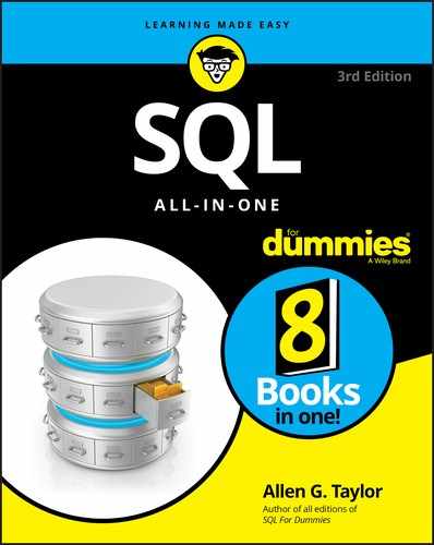
Interviews with society leaders and other members lead you to construct an ER diagram like the one shown in Figure 4-1.

FIGURE 4-1: An ER diagram of OLS research.
This diagram probably seems confusing at first sight, but a little explanation should make it clearer. In the following sections, I first address the relationships, then the maximum cardinality, and finally the minimum cardinality. I also discuss business rules.
Relationships
The relationships define how the important elements of the system are related to one another, as follows:
- Members serve as authors.
- Members serve on research teams.
- Research teams produce papers.
- Authors write papers.
- Authors serve on research teams.
Maximum cardinality
Recall from Book 1, Chapter 2 that the maximum cardinality of a side of a relationship is the largest number of entity instances that can exist on that side. The relationship between members and authors is one-to-one because a member can be one (and only one) author, and an author can be one (and only one) member. An author may or may not be a member, but if she’s a member, she’s only one member.
The relationship between members and research teams is many-to-many because a member can serve on multiple research teams, and a research team can be composed of multiple members.
The relationship between research teams and papers is one-to-many because a research team can produce multiple papers, but each paper is produced by one (and only one) research team.
The relationship between authors and papers is many-to-many because an author may write multiple papers, and a paper may have multiple authors.
The relationship between authors and research teams is many-to-many because an author may serve on multiple research teams, and a research team may include multiple people who are authors.
Minimum cardinality
Minimum cardinality of a side of a relationship is the smallest number of entity instances that can exist on that side. The relationship between members and authors is optional-to-optional because an author of an OLS paper need not be a member of OLS, and a member of OLS need not be an author of a paper.
The relationship between members and research teams is optional-to-optional because not all research-team members need to be members of OLS, and a member of OLS doesn’t need to be a member of a research team.
The relationship between research teams and papers is mandatory-to-optional because all papers must be produced by a research team, but a research team may exist that has not yet produced any papers.
The relationship between authors and papers is mandatory-to-mandatory because a paper must have at least one author, and a person is not considered to be an author until he has participated in the writing of a paper.
The relationship between authors and research teams is optional-to-mandatory because for an author to serve on a research team, the research team must exist, but a research team can exist that doesn’t include any authors.
Business rules
To model a system accurately, you must do more than determine the relevant entities, the attributes and identifiers of those entities, and the relationships among the entities. You must also capture the business rules that the organization follows for that system. Business rules vary from one organization to another, and they can make a big difference in how you model a system. In an educational context, one school may have a rule that at least eight students must sign up for a class for it to be offered. Another school may allow a class to proceed if as few as four students enroll. This would make a difference in the minimum cardinality of the relationship relating courses to students. One airline might cancel a scheduled flight if fewer than five people have bought tickets. Another airline might go ahead with the flight, even if no passengers are aboard. These are differences in business rules.
As a database developer, your job is to find out what your client’s business rules are. You have to ask probing questions of the people you interview. Their business rules are so much a part of their lives that they probably won’t think to mention them to you unless you ask detailed questions about them. Every stakeholder in the client organization has a different perspective on the database system you’re building and is likely to be aware of different business rules, too. For that reason, it’s important to talk to everyone involved and make sure that you flush out all the rules.
With regard to OLS, investigation uncovers several business rules:
- Papers may have multiple coauthors, some of whom may not be members of OLS.
- An OLS member may be a member of multiple research teams.
- Any given paper may be associated with one (and only one) research team.
The OLS example is simple, but it illustrates the depth of thinking you must do about the entities in a system and how they relate to one another.
Transforming the Model
The first step in converting an ER model to a relational model is understanding how the terminology used with one relates to the terminology used with the other. In the ER model, we speak of entities, attributes, identifiers, and relationships. In the relational model, the primary items of concern are relations, attributes, keys, and relationships. How do these two sets of terms relate?
In the ER model, an entity is something identified as being important. Entities are physical or conceptual objects that you want to keep track of. This definition sounds a lot like the definition of a relation. The difference is that for something to be a relation, it must satisfy the requirements of First Normal Form (1NF; see Book 2, Chapter 2). An entity may translate into a relation, but you have to be careful to ensure that the resulting relation is in 1NF.
If you can translate an entity into a corresponding relation, the attributes of the entity translate directly into the attributes of the relation. Furthermore, an entity’s identifier translates into the corresponding relation’s primary key. The relationships among entities correspond exactly with the relationships among relations. Based on these correspondences, it isn’t too difficult to translate an ER model into a relational model. The resulting relational model isn’t necessarily a good relational model, however. You may have to normalize the relations in it to protect it from modification anomalies. You also may have to decompose any many-to-many relationships to simpler one-to-many relationships. After your relational model is appropriately normalized and decomposed, the translation to a relational database is straightforward.
Eliminating any many-to-many relationships
The ER model of the OLS database shown in Figure 4-1 (refer to “Relating the entities to one another,” earlier in this chapter) contains many-to-many relationships. Such relationships can be problematic when you’re trying to create a reliable database, so the usual practice is to decompose a single many-to-many relationship into two equivalent one-to-many relationships. This decomposition involves creating an intersection entity located between the two entities that were originally joined by a many-to-many relationship.
To prepare for the decomposition, first look at the entities involved and their identifiers, as follows:
Entity |
Identifier |
MEMBERS |
MemberID |
AUTHORS |
AuthorID |
RESEARCHTEAMS |
TeamID |
PAPERS |
PaperID |
MemberID uniquely identifies a member, and AuthorID uniquely identifies an author. TeamID uniquely identifies each of the research teams, and PaperID uniquely identifies each of the papers written under the auspices of the OLS.
Three many-to-many relationships exist:
- MEMBERS:RESEARCHTEAMS
- AUTHORS:RESEARCHTEAMS
- AUTHORS:PAPERS
You need to place an intersection entity between the two entities of each of these pairs. You could call the intersection entities MEM-RES, AUTH-RES, and AUTH-PAP. Figure 4-2 shows the data structure diagram for this relational model.
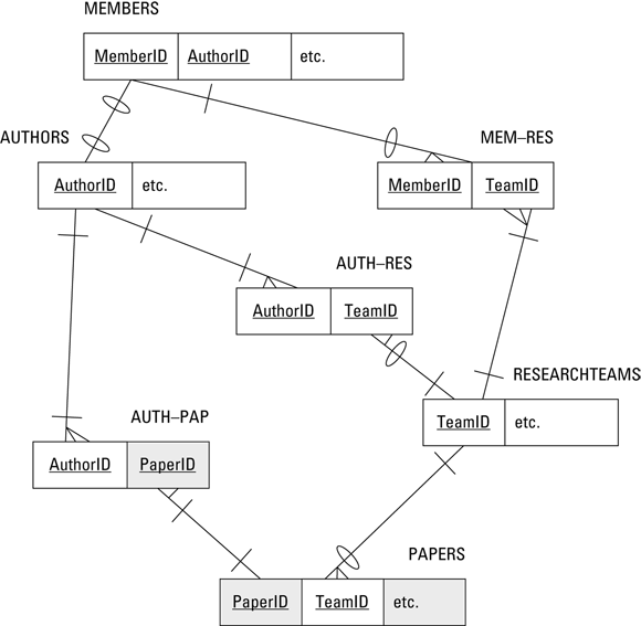
FIGURE 4-2: An ER model representation of the OLS system in Figure 4-1.
This relational model includes four entities that correspond to the four entities in Figure 4-1, plus three intersection entities that replace the many-to-many relationships. There is one one-to-one relationship and seven one-to-many relationships. Minimum cardinality is denoted by slashes and ovals. In the MEMBERS:AUTHORS relationship, for example, an oval, meaning optional, appears on the MEMBERS side of that relationship because an author need not be a member of OLS. Furthermore, a person can be a member of OLS without ever writing a society paper, so an oval appears on the AUTHORS side of the relationship. A slash means mandatory. Similar logic to what is shown for the relationship between MEMBERS and AUTHORS applies to the slashes and ovals on the other relationship lines.
The relations are
- MEMBERS (MemberID, FirstName, LastName, OfficeHeld, Email, Phone, Street, City, State, ZIP)
- AUTHORS (AuthorID, FirstName, LastName)
- RESEARCHTEAMS (TeamID, TeamName, TeamLeaderFirstName, TeamLeaderLastName, ResearchFocus, MeetingLocation, MeetingSchedule)
- PAPERS (PaperID, TeamID, PaperTitle, PrincipalAuthorID, Abstract, WherePublished)
- MEM-RES (MemberID, TeamID)
- AUTH-RES (AuthorID, TeamID)
- AUTH-PAP (AuthorID, PaperID)
Note: The underlines in the list indicate that the underlined attribute is the key of the relation or part of the key.
When you have an ER model that accurately reflects the system being modeled and that contains no many-to-many relationships, the next step is making sure that the model is sufficiently normalized.
Normalizing the ER model
The main reason to normalize a database (as mentioned in Book 2, Chapter 2) is to prevent the appearance of modification anomalies in the data. Such anomalies can lead to the loss of needed data or the introduction of spurious data. Normalization usually entails splitting one table into two (or more) tables that together contain the same information. Each table in a fully normalized database deals with only one idea.
The OLS ER model has four entities: MEMBERS, AUTHORS, RESEARCHTEAMS, and PAPERS. Look at one of these entities in more detail, and consider whether it’s sufficiently normalized.
The MEMBERS entity contains all the relatively stable information that the OLS keeps on its members. It doesn’t say anything about which research teams they’re on or what papers they’ve written, which could change frequently; it contains only personal information.
Figure 4-3 diagrammatically depicts the MEMBERS entity in the ER model and its corresponding relation in the relational model. At the bottom in Figure 4-3, MemberID is underlined to signify that it’s the primary key of the MEMBERS relation. Every member has a unique MemberID.
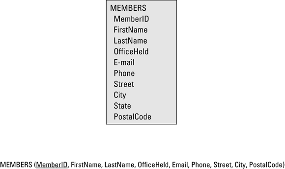
FIGURE 4-3: The MEMBERS entity (top) and the MEMBERS relation.
The MEMBERS entity maps exactly to the MEMBERS relation. It’s natural to ask whether the MEMBERS relation is in Domain-Key Normal Form (DKNF) (see Book 2, Chapter 2). Clearly, it isn’t. It isn’t even in Second Normal Form (2NF). State is functionally dependent on PostalCode, which isn’t a key.
You could normalize the MEMBERS relation by breaking it into two relations, as follows:
MEMBERS (<b>MemberID</b>, FirstName, LastName, OfficeHeld, Email, Phone, Street, City, PostalCode)
POSTAL (<b>PostalCode</b>, State)
These two relations are in 2NF and also in DKNF. They also demonstrate a new idea about keys. The two relations are closely related because they share attributes. The PostalCode attribute is contained in both the MEMBERS and the POSTAL relations. MemberID is called the primary key of the MEMBERS relation. It must uniquely identify each tuple — the ER model equivalent of a row in a database table — in the relation. Similarly, PostalCode is the primary key of the POSTAL relation.
In addition to being the primary key of the POSTAL relation, PostalCode is a foreign key in the MEMBERS relation. It provides a link between the two relations. An attribute need not be unique in a relation in which it serves as a foreign key, but it must be unique at the other end of the relationship, where it serves as the primary key.
After you normalize a relation into DKNF, as I did with the original MEMBERS relation, it’s wise to ask yourself whether full normalization makes sense in this specific case. Depending on how you plan to use the relations, you may want to denormalize somewhat to improve performance. In this example, you probably want to fold the POSTAL relation back into the MEMBERS relation. Generally, if you need any part of a person’s address, you need all of it.
Creating Tables
You can create a database (including all its tables) by typing SQL statements into your computer using tools provided by the DBMS, such as MySQL’s MySQL Workbench or SQL Server’s Management Studio; by including embedded CREATECREATE statements in a module from which they can be called by a procedural language program.
Using interactive SQL, you can start building your OLS database by creating the MEMBERS table. Here’s the Data Definition Language (DDL) code to do it:
CREATE TABLE MEMBERS (
MemberID Integer PRIMARY KEY,
FirstName Char (15),
LastName Char (20) NOT NULL,
OfficeHeld Char (20),
Email Char (50),
Phone Char (20),
Street Char (25),
City Char (20),
State Char (2),
Zip Char (10) );
Note: Each line within the outer parentheses (except the last one) in the preceding statement above is terminated by a comma. The comma tells the DBMS where one field ends and the next one starts. The DBMS doesn’t pay any attention to what line something is printed on. The separation of this single statement on multiple lines is for the convenience of human readers, not for the DBMS.
The preceding SQL code creates a MEMBERS table. MemberID is the primary key of the table. Applying the NOT NULL constraint to the LastName attribute ensures that you know at least a member’s last name even when you may not have complete information on that member. For each Character field, you must explicitly specify the maximum length of an entry in that field. The NOT NULL constraint is an example of a column constraint, which applies only to a single column. By contrast, a table constraint applies to an entire table. In the following code, I create the AUTHORS table and illustrate the use of a table constraint in the process:
CREATE TABLE AUTHORS (
AuthorID Integer PRIMARY KEY,
MemberID Integer,
FirstName Char (15),
LastName Char (20) NOT NULL,
CONSTRAINT MemFK FOREIGN KEY (MemberID)
REFERENCES MEMBERS (MemberID)
ON DELETE NO ACTION );
Note: In the preceding code, no comma appears at the end of the CONSTRAINT line because the REFERENCES clause is part of that line. No comma appears at the end of the REFERENCES line because ON DELETE NO ACTION is also part of the CONSTRAINT line.
The PRIMARY KEY constraint is a table constraint. It applies to the entire table. In this case, it says that AuthorID is the primary key of the AUTHORS table.
MemFK is a foreign key constraint and another example of a table constraint. It links the MemberID field in the AUTHORS table to the MemberID field in the MEMBERS table. The ON DELETE NO ACTION clause means that if a person is ever deleted from the AUTHORS table, she isn’t also deleted from the MEMBERS table. If for any reason a paper is retracted by the journal that published it, a supposed author may suddenly become a nonauthor, but this change wouldn’t necessarily affect that person’s membership in the OLS.
Note: I used the convention of naming foreign key constraints by taking the first several letters of the key field and appending FK to them (for example, MemFK). This convention makes it immediately obvious that I’m discussing a foreign key.
You can create the rest of the tables in a similar manner. Here’s the SQL statement that creates the RESEARCHTEAMS table:
CREATE TABLE RESEARCHTEAMS (
TeamID Integer PRIMARY KEY,
TeamName Char (30),
TeamLeaderFirstName Char (15),
TeamLeaderLastName Char (20),
ResearchFocus Char (50),
MeetingLocation Char (50),
MeetingSchedule Char (30) );
The PAPERS table is defined in a similar fashion:
CREATE TABLE PAPERS (
PaperID Integer PRIMARY KEY,
TeamID Integer,
PaperTitle Char (50),
PrincipalAuthorID Integer,
Abstract Char (300),
WherePublished Char (30) );
The linking tables MEM-RES, AUTH-RES, and AUTH-PAP, derived from the intersection relations with the same names in the relational model, are also defined the same way but also include foreign key constraints, as follows:
CREATE TABLE MEM-RES (
MemberID Integer NOT NULL,
Team ID Integer NOT NULL,
CONSTRAINT MemFK FOREIGN KEY (MemberID)
REFERENCES MEMBERS (MemberID)
ON DELETE CASCADE,
CONSTRAINT TeamFK FOREIGN KEY (TeamID)
REFERENCES RESEARCHTEAMS (TeamID)
ON DELETE CASCADE );
The foreign key constraint MemFK establishes the fact that the MemberID field in the MEM-RES table corresponds to the MemberID field in the MEMBERS tables. Corresponding fields need not have the same names, but it reduces confusion if they do. The ON DELETE CASCADE clause has the effect of removing a person from all research teams when his membership in the OLS expires and he is removed from the MEMBERS table.
The TeamFK constraint operates in a similar manner. When a research team is disbanded, all references to that team in MEM-RES are deleted. This deletion has the effect of updating members’ information so that they’re no longer shown as being members of the disbanded team. The members’ other team memberships are unaffected.
The final two linking tables, AUTH-RES and AUTH-PAP, are defined in the same way that MEM-RES was defined, as follows:
CREATE TABLE AUTH-RES (
AuthorID Integer NOT NULL,
Team ID Integer NOT NULL,
CONSTRAINT AuthFK FOREIGN KEY (AuthorID)
REFERENCES AUTHORS (AuthorID)
ON DELETE CASCADE,
CONSTRAINT TeamFK FOREIGN KEY (TeamID)
REFERENCES RESEARCHTEAMS (TeamID)
ON DELETE CASCADE );
CREATE TABLE AUTH-PAP (
AuthorID Integer NOT NULL,
Paper ID Integer NOT NULL,
CONSTRAINT AuthFK FOREIGN KEY (AuthorID)
REFERENCES AUTHORS (AuthorID)
ON DELETE CASCADE,
CONSTRAINT PapFK FOREIGN KEY (PaperID)
REFERENCES PAPERS (PaperID)
ON DELETE CASCADE );
AuthFK is a table constraint, so the fact that a constraint in AUTH-RES has the same name as a constraint in AUTH-PAP doesn’t matter. The DBMS won’t confuse the two constraints.
At this point, all the tables have been defined, and they’re ready to accept data.
Changing Table Structure
Suppose that after you create a table, you decide that you need to add a new column to it or perhaps remove an existing column that serves no purpose. The DDL ALTER statement is included in SQL for these purposes. If you want to add a Fax column to the MEMBERS table, for example, you could do so with the following SQL statement:
ALTER TABLE MEMBERS
ADD COLUMN Fax Char (20) ;
You can remove columns by using a similar statement, as follows:
ALTER TABLE MEMBERS
DROP COLUMN Fax ;
Removing Tables
It’s really easy to get rid of tables you no longer want — perhaps too easy. For that reason, maintaining a rigorous backup discipline is important. To remove a table from your database, the DROP statement is all you need:
DROP TABLE PAPERS ;
There’s no going back after you use the DROP statement. SQL doesn’t ask you whether you really want to perform such a drastic act; it just blows away the table and then waits for your next instruction.
Designing the User Interface
Every database application has a user interface, which consists of what the user sees on her screen and the key presses, mouse movements, and clicks that she performs to interact with the application. The screen presents the user options for actions to perform, queries to process, or reports to view. SQL isn’t designed to perform any of these user interface tasks. In any relational database application, the part created by the procedural language takes care of these tasks. Your job as application developer is to make sure that the user interface is intuitive and easy to use — and, of course, that it provides access to all the functionality that the application possesses. Book 5, Chapter 5 provides an example of user interface design.