
22
Systems Engineering Approach for Implementing Data Fusion Systems
Christopher L. Bowman and Alan N. Steinberg
CONTENTS
22.2 Architecture for Data Fusion
22.2.1 Role of Data Fusion in Information Processing Systems
22.2.2 The Role for the DNN Architecture
22.2.3 Components of the DNN Technical Architecture for DF&RM System Development
22.2.4.1 Data Fusion Node Processing
22.2.4.2 Resource Management Node Processing
22.2.4.3 Comparison of the Dual Data Association and Response Planning Functions at Each DF&RM Level
22.3 Data Fusion System Engineering Process
22.4 Sample Applications of the DF&RM DNN Architecture
22.4.1 Level 2 Fusion DNN Application Example
24.4.2 Level 3 Fusion DNN Application Example
22.4.3 Level 4 DF&RM DNN Application Example
22.4.4 Dual RM DNN Application Example
22.4.5 DF&RM System Engineering as a Level 4 Resource Management Problem
22.5 The DF&RM Model Unification Provided by the DNN Architecture
22.5.2 Bedworth and O’Brien’s Omnibus Model
22.5.3 The Kovacich Fusion Taxonomy
22.1 Scope
This chapter defines a systematic method for characterizing and developing data fusion and resource management (DF&RM) systems. This is defined in the form of a technical architecture at the applications layer.
Although DF&RM can and has been performed by people with various degrees of automated tools, there is increasing demand for more automation of data fusion and response management functions. In particular, there is a need for such processes operating in open, distributed environments. The exponential increase in DF&RM software development costs has increased the demand to cease building one-of-a-kind DF&RM software systems. Software technical architectures help to achieve this by defining the standard software components, interfaces, and engineering design methodology. This provides a toolbox to guide software designers and to organize the software patterns that they develop (thus easing reusability).
The intent of this chapter is to provide a common, effective foundation for the design and development of DF&RM systems. The DF&RM technical architecture provides guidelines for selecting among design alternatives for specific DF&RM system developments.
This system’s engineering approach has been developed to provide
A standard model for representing the requirements, design components, their interfaces, and performance assessment of DF&RM systems
An engineering methodology for developing DF&RM systems to include the selection of the DF&RM system architecture and the analysis of technique alternatives for cost-effective satisfaction of system requirements
This DF&RM technical architecture1, 2 and 3 builds on a set of Data Fusion Engineering Guidelines, which was developed in 1995–1996 as part of the U.S. Air Force Space Command’s Project Correlation.* The present work extends these guidelines by proposing a technical architecture as defined by the Department of Defense (DoD) Architecture Framework for system engineering (www.defenselink.mil/nii), thereby establishing the basis for rigorous problem decomposition, system architecture design, and technique application.
Integral to the guidelines is the use of a functional model for characterizing diverse DF&RM system architectures. This architecture functional paradigm has been found to successfully capture the salient operating characteristics of the diverse automatic and manual approaches that have been employed across great diversity of data fusion applications. This DF&RM system paradigm can be implemented in human, as well as automated processes, and in hybrids involving both.
The recommended architecture concept represents DF&RM systems as interlaced networks—earlier termed DF&RM trees—of data fusion processing nodes and resource management processing nodes that are amenable to standard dual representations. The interlacing of data fusion nodes with resource management nodes enables fast response loops. The close relationship between fusion and management, both in interactive operation and in their underlying design principles, plays an important part in effective system design and in comparing alternative methods for achieving DF&RM system designs.
The largely heuristic methods presented in the Project Correlation Data Fusion Engineering Guidelines are amenable to more rigorous treatment. System engineering, and specifically data fusion system engineering, can be viewed as a planning (i.e., resource management) process. Available techniques and design resources can be applied to meet an objective criterion: cost-effective system performance. Therefore, the techniques of optimal planning can be applied to building optimal systems. Furthermore, the formal duality between data fusion and resource management first propounded by Bowman, enables data fusion design principles developed over the past 30+ years to be applied to the dual problems of resource management. As system engineering is itself a resource management problem, the resource management architecture principles described herein can be used to organize the building of any software system.*
In summary, this chapter provides a description of how the DF&RM dual node network (DNN) architecture organizes and unifies applications-layer software approaches to DF&RM. Refinements of the Joint Directors of Laboratories (JDL) fusion model levels and dual resource management process model levels are proposed to take advantage of their duality to bootstrap the less mature resource management field. The levels are used to divide and conquer DF&RM software developments. This enables the batching of data belief functions for combination within fusion and the batching of resource tasking within management. Comparisons to other fusion models and examples of the application of the DNN for affordable fusion and management processing using these levels are discussed.
22.2 Architecture for Data Fusion
22.2.1 Role of Data Fusion in Information Processing Systems
Data fusion is the process of combining data/information to estimate or predict the state of some aspect of the world.1 Fusion provides fused data from the sources to the user and to resource management, which is the process of planning/controlling response capabilities to meet mission objectives (Figure 22.1).
In this section, refinements of the JDL data fusion model and dual extensions for resource management are described and applied in the DF&RM DNN software technical architecture. The motivation for this and earlier versions of the JDL data fusion model has been to facilitate understanding of the types of problems for which data fusion is applicable and to define a useful partitioning of DF&RM solutions.

FIGURE 22.1
Fusion and management lie between observe and act.
The JDL data fusion model is a functional model. It was never conceived as a process model or as a technical architecture. Rather, it has been motivated by the desire to reduce the community’s perceived confusion regarding many elements of fusion processes. The model was developed to provide a common frame of reference for fusion discussions and to facilitate the understanding and recognition of the types of problems for which data fusion is applicable and also as an aid to recognizing commonality among problems and the relevance of candidate solutions.
As stated by Frank White, the original JDL panel chairman, much of its (JDL model) value derives from the fact that identified fusion functions have been recognizable to human beings as a model of functions they were performing in their own minds when organizing and fusing data and information. It is important to keep this human centric sense of fusion functionality since it allows the model to bridge between the operational fusion community, the theoreticians and the system developers.
The framework of the model has been useful in categorizing investment in automation and highlighting the difficulty of building automated processes that provide functionality in support of human decision processes particularly at the higher levels where reasoning and inference are required functions. The dual resource management levels described herein are offered as a starting place from which to evolve the same benefits for the resource management community.
The suggested revised data fusion function at the functional levels2 are based on the entities of interest to information users (Figure 22.2) with revised fusion levels defined as follows:
Level 0 (L0). Signal/feature assessment—estimation and prediction of signal or feature states
Level 1 (L1). Entity assessment—estimation and prediction of entity parametric and attributive states (i.e., of entities considered as individuals)
Level 2 (L2). Situation assessment—estimation and prediction of the structures of parts of reality (i.e., of relationships among entities and their implications for the states of the related entities)

FIGURE 22.2
Recommended revised data fusion model. (From Steinberg, A.N. and Bowman, C.L., Rethinking the JDL Fusion Levels, NSSDF JHAPL June, 2004.)Level 3 (L3). Impact assessment—estimation and prediction of the utility/cost of signal, entity, or situation states; including predicted impacts given a system’s alternative courses of action (COAs)
Level 4 (L4). Process assessment—estimation and prediction of a system’s performance as compared to given desired states and measures of effectiveness
The JDL fusion levels provide a historically useful and natural batching of fusion nodes (i.e., into signals, entities, relationships, and impacts) that should be considered in a fusion system design to achieve the knee-of-the-curve in performance versus cost. The level 1 entities of interest are defined by the user as individual objects. Level 0 characterizes patterns in received data to estimate types and characteristics of features and signals. This may be done without necessarily posting a specific causative level 1 entity. Their relationships of interest (e.g., as defined by an ontology of their aggregates, attacks, cues, etc.) are the focus of level 2 processing. This level 2 processing can be represented with multiple predicates as described in Ref. 2, with single predicates (e.g., as defined by a taxonomy of entity classes) used for the entity attributes estimated in level 1. The use of the DNN architecture for level 2 and level 3 fusion provides the system designer with techniques to interlace the levels 2 and 3 processes and the functional partitioning for each DF&RM node. The processing at these DF&RM levels are not necessarily performed in sequential order and two or more levels may need to be integrated into common nodes to achieve increased performance albeit at higher complexity/cost.
The most significant change, from earlier versions1,2 is the removal of process management from fusion level 4. Process management is now found within the new resource management levels, as suggested in Ref. 1. Process assessment is retained in the fourth level of JDL model for fusion (i.e., process assessment has always been included in the JDL level 4 fusion). The consideration of fusion process management as a resource management function provides a rich set of tools for segmenting and developing process management software using DNN resource management nodes much as they are applied for resource management process refinement (see Section 22.4). The restriction of level 4 fusion to process assessment provides the benefit for developing performance evaluation (PE) systems using the DNN data fusion architecture (see Section 22.3). Examples of levels 2 and 3 fusion processes are given in Sections 22.1 and 22.2, respectively. A discussion of how the DF&RM DNN architecture unifies numerous DF&RM models is given in Section 22.5. Before presenting these the role and significant components of the applications-layer DNN architecture are reviewed in Sections 22.2 and 22.3, respectively.
22.2.2 The Role for the DNN Architecture
Information technology and concepts are evolving rapidly in the global web. Paraphrasing Frank White, the evolution toward client services including web services, agent-based computing, semantic web with its ontology development offers the potential for a widely distributed information environment. Network services are receiving the bulk of the attention at present but the importance of the information services is becoming recognized. Information services center on content including data pedigree, contextual metadata, and contribution to the situational awareness. Data and information fusion is cited as a central, enabling technology to satisfy the inherent informational needs. From the fusion community perspective the ability to achieve automated fusion (e.g., belief function combination) is dependent on the data pedigree, metadata, context services, and the architecture standards that evolve to prescribe them. Thus, the user identifiable functional components of the fusion process as embodied in a fusion architecture are critical to providing affordable distributed information services.
The increasing demand for more automation of data fusion and response management functions operating in open distributed environments makes it imperative to halt the exponential increase in DF&RM software development costs and building of one-of-a-kind DF&RM software systems.
Architectures are frequently used as mechanisms to address a broad range of common requirements to achieve interoperability and affordability objectives. An architecture (IEEE definition from ANSI/IEEE Standard 1471-2000) is a structure of components, their relationships, and the principles and guidelines governing their design and evolution over time. An architecture should
Identify a focused purpose with sufficient breadth to achieve affordability objectives
Facilitate user understanding/communication
Permit comparison, integration, and interoperability
Promote expandability, modularity, and reusability
Achieve most useful results with least cost of development
As such, an architecture provides a functional toolbox to guide software designers and organize the software patterns that they develop (thus easing reusability).
The DoD framework for architectures (Department of Defense Architecture Framework [DoDAF]) provides a common basis for developing architectures and defines standard presentation products for each role: operational, systems, and technical architectures. The DF&RM DNN architecture is a technical architecture as shown in Figure 22.3. The DoD framework promotes effective communications of operational analysis and systems engineering from design to operations. It is used to visualize and define operational and technical concepts, plan process improvement, guide systems development, and improve interoperability. The DoD architecture framework is complementary to the Defense Information Systems Agency (DISA) Technical Architecture Framework for Information Management (TAFIM), the Common Operating Environment (Figure 22.4), and the layered network enterprise (Figure 22.5). The DF&RM DNN architecture provides a unification and organization of the DF&RM algorithmic approaches at the applications layer as depicted in Figure 22.6.

FIGURE 22.3
Role for DF&RM DNN architecture within the DoD architecture framework.

FIGURE 22.4
The simplified COE/C4I architecture.

FIGURE 22.5
Layered view of functionality within a networked enterprise.
The criteria for the selection of the DNN architecture for DF&RM at the applications layer includes the following:
Breadth. Permits representation and comparison of all aspects of fusion
Depth. Sufficient level of detail to represent and compare all approaches to fusion (e.g., individual fusion patterns)
Affordability. Provides engineering guidelines for the application of the architecture to fusion system development to achieve useful results while minimizing development costs
Understandability. Familiarity in community and facilitation of user understanding and communication of all fusion design alternatives
Hierarchical. Sufficient module structure to enable incorporation of legacy codes at varying levels of granularity (e.g., whole fusion node, data association, hypothesis scoring, estimation, tracking filters, attribute/ID confidence updating)

FIGURE 22.6
A DF&RM architecture is needed at the applications layer.
Levels of abstraction. Permits abstraction of fusion processes higher in the chain of command to balance depth versus breath as needed
Extendibility. Ease of extension to highly related processes, especially resource management, and to new applications supporting code reuse
Maturity. Completeness of architecture components and relationships yielding reduced risk in applications
22.2.3 Components of the DNN Technical Architecture for DF&RM System Development
As data fusion is the process of combining data/information to estimate or predict the state of some aspect of the world1 and resource management is the process for managing/controlling response capability to meet mission objectives, it is important to remember the definitions of optimal estimation and control. Namely
The estimation problem consists of determining an approximation to the time history of a system’s response variables from erroneous measurements.5
An optimal estimator is a computational algorithm that processes measurements to deduce a minimum error estimate of the state of a system by utilizing: knowledge of system and measurements dynamics, assumed statistics of system noises and measurements errors, and initial condition information.6
The control problem is that of specifying a manner in which the control input should be manipulated to force the system to behave in some desired fashion. If a performance measure is introduced to evaluate the quality of the system’s behavior, and the control input is to be specified to minimize or maximize this measure, the problem is one of optimal control.5
The solution of the Riccati equation provided by estimation theory provides the solution of the quadratic optimal control problem as described in Figure 22.7. Data fusion contains the estimation process that is defined by the data preparation, and association function such as resource management contains the control process that is defined by the task preparation and planning functions. As such the estimation and control duality can be extended to DF&RM (Figure 22.8). Figure 22.9 depicts this for the original data fusion tree architecture developed over 20 years ago.7,8
DF&RM systems can be implemented using a network of interacting fusion and management nodes. The dual DF&RM levels provide insight into techniques to support the designs for each. The key components in the DF&RM DNN architecture are depicted in Figure 22.10. The fusion and management node networks are interlaced to provide faster local feedback as well as data sharing and response coordination. A sample interlaced DF&RM node network is shown in Figure 22.11. The dual fan-in fusion and fan-out management networks are composed of DF&RM nodes whose dual processing components are described in Figure 22.12.

FIGURE 22.7
The estimation and control duality and the separation principle.

FIGURE 22.8
Duality extensions yield similar methodology for data fusion and resource management.

FIGURE 22.9
DF&RM duality allows exposure of the solution approaches and enables software reuse.

FIGURE 22.10
Dual node network architecture components.
The Kalman estimate is the expected value of the state, x, given the measurements. This estimate is optimal for any symmetric and convex performance measure. The separation principle9 implies that the optimal filter gain matrix is independent of the parameters in the performance loss function (and dependent on the plant statistical parameters) whereas the optimal feedback control gain matrix is independent of the plant statistical parameters (and dependent on the performance objective parameters). This duality enables the more mature field of data fusion to rapidly advance resource management much as estimation did for control over 35 years ago, and suggests that fusion is driven by the data and management is driven by the performance objectives. This duality motivates the following description of the levels 1 through 4 fusion and management processes. The levels are partitioned due to the significant differences in the types of data, resources, models, and inferencing necessary for each level as follows:

FIGURE 22.11
Sample interlaced tree of DF&RM nodes.

FIGURE 22.12
DF&RM node duality facilitates understanding of alternatives and reuse.
• Signal/feature assessment—Level 0: estimation of entity feature states |
• Entity assessment—Level 1: estimation of entity states |
• Situation assessment—Level 2: estimation of entity relationship states |
• Impact assessment—Level 3: estimation of the mission impact of fused states |
• Process assessment—Level 4: estimation of the DF&RM system MOE/MOP states |
• Resource signal management—Level 0: management of resource signals |
• Resource response management—Level 1: management resource responses |
• Resource relationship Management—Level 2: management of resource relationships |
• Mission objective management—Level 3: management of mission objectives |
• Process/knowledge management—Level 4: management of the DF&RM system engineering and products |
These levels provide a canonical partitioning that should be considered during DF&RM node network design. Though not mandatory, such partitioning reduces the complexity of the DF&RM software. An example of the clustering of DF&RM nodes by the above 0/1/2/3 levels, which enables fast response feedback, is shown in Figure 22.13. This shows how interlaced fusion and management nodes can be organized by level into similar response timeliness segments. The knowledge management for the interactions with the user occurs as part of the response management processing as needed. Figure 22.14 shows a distributed level 1 fusion network over time that has individual sensor level 1 fusion nodes providing tracks to the ownship multiple sensor track-to-track fusion nodes. The ownship fusion track outputs are then distributed across all the aircraft for internetted cooperative fusion. Further batching of the processing of each fusion level (i.e., to reduce complexity/cost) can then be performed to achieve the knee-of-the-curve fusion network, as depicted in Figure 22.15. A dual knee-of-the-curve design process can be used for resource management network design.
All the fusion levels can be implemented using a fan-in network of fusion nodes where each node performs data preparation, data association, and state estimation. All the management levels can be implemented using a fan-out network of management nodes where each node performs response task preparation, response task planning, and resource state control. These levels are not necessarily processed in numerical order or in concert with the corresponding dual fusion level. Also, any one can be processed on their own given their corresponding inputs. The DF&RM function-processing levels are based on what the user defines as his entities and resources of interest. The five DF&RM dual processing levels are described in more detail below in their dual pairs per level:

FIGURE 22.13
Sample interlaced sequential level DF&RM system network.
Resource signal management level 0. Management to task/control specific resource response actions (e.g., signals, pulses, waveforms, etc.)
Signal/feature assessment level 0. Fusion to detect/estimate/perceive specific source entity signals and features
Resource response management level 1. Management to task/control continuous and discrete resource responses (e.g., radar modes, countermeasures, maneuvering, communications)
Entity assessment level 1. Fusion to detect/estimate/perceive continuous parametric (e.g., kinematics, signature) and discrete attributes (e.g., IFF, class, type, ID, mode) of entity states
Resource relationship management level 2. Management to task/control relationships (e.g., aggregation, coordination, conflict) among resource responses
Situation assessment level 2. Fusion to detect/estimate/comprehend relationships (e.g., aggregation, causal, command/control, coordination, adversarial relationships) among entity states
Mission objective management level 3. Management to establish/modify the objective of levels 0, 1, 2 action, response, or relationship states
Impact assessment level 3. Fusion to predict/estimate the impact of levels 0, 1, or 2 signal, entity, or relationship states

FIGURE 22.14
Sequential distributed fusion network over time, sensors, and platforms.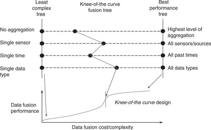
FIGURE 22.15
Fusion network selected to balance performance and complexity.Process/knowledge management level 4: Design, adjudication, and concurrency management to control the system engineering, distributed consistent tactical picture (CTP), and product relevant context concurrency
Process assessment level 4: Performance, consistency, and context assessment to estimate the fusion system measures of performance/effectiveness (MOP/MOE)
22.2.4 DF&RM Node Processing
22.2.4.1 Data Fusion Node Processing
Data fusion is the process of combining data/information to estimate or predict the state of some aspect of the world. An example of the fusion node processes is shown in Figure 22.16.
The fusion node paradigm for all levels of fusion involves the three basic functions of data preparation, data association, and entity-state estimation, as shown in Figure 22.17. The means for implementing these functions and the data and control flow among them will vary from node to node and from system to system. Nonetheless, the given paradigm has been a useful model for characterizing, developing, and evaluating automatic and human-aided fusion systems.
Data preparation (sometimes termed data alignment or common referencing) preprocesses data received by a node to permit comparisons and associations among the data. Alignment involves functions for
Common formatting and data mediation
Spatiotemporal alignment
Confidence normalization
Data association assigns data observations—received in the form of sensor measurements, reports, or tracks—to hypothesized entities (e.g., vehicles, ships, aircraft, satellites, and abnormal events). We will refer to the resulting entity estimates based on this association as tracks. The general level 1 data association problem is a labeled set-covering problem where the labels on the associated data sets are for false or valid entity tracks. In many applications the set-covering problem can be simplified to a set-partitioning problem. An example of set partitioning for abnormal event track association is to limit an abnormality report to associating to only one event track. Before a sensor observation and its associated information are fused with an existing track, the hypothesis that the observation is of the same entity as that represented by the track information can be generated, evaluated, and one or many selected.* The association process is accomplished via the following three functions:

FIGURE 22.16
Sensor fusion exploits sensor commonalities and differences.

FIGURE 22.17
The DF&RM DNN technical architecture fusion node functional paradigm.
Hypothesis generation. Identifying sets of sensor reports and existing tracks (report associations) that are feasible candidates for association
Hypothesis evaluation. Determining the confidence (i.e., quality) of the report to track association or nonassociation as defined by a particular metric
Hypothesis selection. Determining which of the report-to-track associations, track propagations or deletions, and report track initiations or false alarm declarations the fusion system should retain and use for state estimation
State estimation and prediction use the given fusion node batch of data to refine the estimates reported in the data and infer entity attributes and for level 2 fusion their relations. For example, kinematics measurements or tracks can be filtered to refine kinematics states. Kinematics and other measurements can be compared with entity and situation models to infer features, identity, and relationships of entities in the observed environment. This can include inferring states of entities other than those directly observed. This also applies to mission impact prediction in level 3 fusion based on course action hypothesis generation, evaluation, and selection.
22.2.4.2 Resource Management Node Processing
Resource management is the process of planning/controlling response capabilities to meet mission objectives. An example of the dual resource management node processes for sensor management is shown in Figure 22.18.
Given this duality, the maturity of data fusion can be used to better understand the less mature resource management field, much like the duality of estimation did for control over 30 years ago. In doing so, the fusion system development process becomes intertwined with the resource management system development within each design phase. As multinodal data fusion networks are useful in partitioning the data association and state estimation problems, so are resource management networks useful in partitioning planning and control problems. The data fusion node performs an association/estimation process, and the resource management node performs a response planning and execution process. Both of these DF&RM node networks—one synthetic (i.e., constructive) and the other analytic (i.e., decompositional)—are characteristically recursive and hierarchical.
As depicted in Figure 22.19, the resource management node contains functions that directly correspond to those of the dual data fusion node. The resource management node is described as follows:
Task preparation—converts prioritized needs to prioritized candidate tasks for the current resource management node

FIGURE 22.18
Sensor management exploits sensor commonalities and differences.
FIGURE 22.19
Duality of DF&RM nodes facilitates understanding and reuse.Response task planning:
Plan generation—generate feasible resource task plans (e.g., candidate sequences of tasks that compose a feasible response plan)
Plan evaluation—evaluate alternative feasible resource response task plans (e.g., with Bayesian cost, possibilistic, expert system rules, ad hoc, etc.)
Plan selection—select, delete, or initiate response task plans (e.g., deterministic, probabilistic, multiple hypothesis testing (MHT), n-dimensional partitioning, or set covering)
Control (i.e., resource tasking plan execution)—generates the resource control commands to implement the selected resource allocation plan
Planning is a process that is analogous to data association in data fusion. Planning functions that correspond to association hypothesis generation, evaluation, and selection are involved: (a) plan generation involves searching over a number of possible actions for assembly into candidate multiple or single resource plan segments, which are passed to (b) plan evaluation and (c) plan selection. Plan generation, plan evaluation, and plan selection offer challenges similar to those encountered in designing the corresponding dual data fusion functions. As with hypothesis generation in data fusion, plan generation involves potentially massive searches, which must be constrained in practical systems. The objective is to reduce the number of feasible plans for which a detailed evaluation is required. Challenges for plan evaluation lie in the derivation of efficient scoring schemes capable of reflecting the expected utility of alternative resource response plans. Candidate plans, that is, schedules of tasking for system resources, can be assembled recursively. The level of planning is adapted on the basis of
The assessed utility relative to the mission goals of the given plan segment as currently developed
The time available for further planning
For case (a), near-term plan segments tend to be constructed in greater detail than far-term ones, for which the added expenditure in planning resources may outweigh the confidence that the plan will still be appropriate at execution time.
Planning can be accomplished by recursively partitioning a goal into candidate sets of subgoals (plan generation) and combining them into a composite higher-level plan (plan selection). At each level, candidate plans are evaluated with regard to their effectiveness in achieving assigned goals, the global value of each respective goal, and the cost of implementing each candidate plan (plan evaluation). By evaluating higher-level cost/payoff impacts, the need for deeper planning or for selecting alternate plans is determined. In many applications, plan selection can be an NP-hard (i.e., not proven to be a linearly hard) problem—a search of multiple resource allocations over n future time intervals. Also, dual MHT and probabilistic planning/control approaches are exposed for consideration. In addition, dual fusion and management separation principles can be derived.
Contentions for assigning available resources can be resolved by prioritized rescheduling on the basis of time sensitivity and predicted utility of contending allocations. Each resource management node can receive commands from level 2 resource management nodes that are determining resource coordination and conflict plans. For example, in countermeasures management in a combat aircraft, evaluation of self-protection actions must consider detectable signature changes, flight path changes, or emissions that could interfere with another sensor. level 2 resource management nodes respond by estimating the impact of such effects on the mission objectives that are maintained by level 3 resource management nodes. In this way, response plans responsive to situation-dependent mission goals are assembled in a hierarchical fashion.
22.2.4.3 Comparison of the Dual Data Association and Response Planning Functions at Each DF&RM Level
Figure 22.20 describes the data association processes when the fusion processing is segmented by fusion level. Figure 22.21 does the same for response planning functions when the resource management processing is segmented by resource management level.

FIGURE 22.20
Data association problems occur at each fusion level.

FIGURE 22.21
Response planning problems occur at each management level.
22.3 Data Fusion System Engineering Process
The DF&RM DDN architecture components and their implied relationships have been discussed in Sections 22.2.3 and 22.2.4. The engineering process discussed in this chapter involves a hierarchical decomposition of system-level requirements and constraints. Goals and constraints are refined by feedback of performance assessments. This is an example of a goal-driven problem-solving approach, which is the typical approach in system engineering. More general approaches to problem-solving are presented by Bowman et al. and by Steinberg.25 As depicted in Figure 22.22, goal-driven approaches are but one of four approaches applicable to various sorts of problems. In cases where it is difficult to state system goals—as in very experimental systems or in those expected to operate in poorly understood environments—the goal-driven system engineering approach will integrate elements of data-, technique-, or model-driven methods.25
This section describes DF&RM DNN architecture principles and guidelines governing DF&RM software design and evolution over time as shown in Figure 22.23. A key insight, first presented in Ref. 10 is in formulating the system engineering process as a resource management problem; allowing the application of Bowman’s model4 of the duality between data fusion and resource management. The DF&RM DNN technical architecture provides standardized representation for
Coordinating the design of data fusion processes
Comparing and contrasting alternative designs
Determining the availability of suitable prior designs
The four phases of the DNN architecture engineering methodology are defined as follows:
Fusion system role design. Analyze system requirements to determine the relationship between a proposed data fusion system and the other systems with which it interacts.
Fusion tree design. Define how the data is batched to partition the fusion problem.

FIGURE 22.22
Types of problem-solving approaches.
FIGURE 22.23
The DNN architecture DF&RM system engineering process.Fusion node design. Define the data and control flow within the nodes of a selected fusion tree.
Fusion algorithm design. Define processing methods for the functions to be performed within each fusion node (e.g., data association, data alignment, and state estimation/prediction).
More specifically, the CONOPS and blackbox DF&RM system role optimization is performed in phase 1. The DF&RM levels described in Section 22.2.3 typically provide the basis for the highest segmentation of the DF&RM software development process during phase 2 of the DNN software engineering methodology. The requirements and MOP refinement are tailored to support the design optimization for each sequential phase. The optimization of the algorithms for each DF&RM node is performed in phase 3. The selection or development of software patterns organized using the DNN architecture toolbox is performed in phase 4. The software PE at the end of phase 4 can be accomplished with the level 4 process assessment system. When this methodology is applied to the level 4 system development then the level 4 MOPs are used. This recurrent process is usually cut-off here due to PE system cost limitations. A summary of this engineering processing for data fusion is shown in Figure 22.24.
This methodology can be used in a spiral development process to support rapid prototyping. These spirals progress as typified in Figure 22.25 to achieve increasing technology readiness levels (TRL). These TRLs have been adapted from NASA to describe technology maturity. The lower levels enable user feedback to reduce risk. Their abbreviated descriptions are as follows:
TRL 1. Basic principles observed and reported
TRL 2. Technology concept and application formulated

FIGURE 22.24
Data fusion system engineering phases and products.
FIGURE 22.25
Spiral development cycles lead to increased technology readiness levels.TRL 3. Proof of concept
TRL 4. Component validated in laboratory environment
TRL 5. Component validated in relevant environment
TRL 6. Prototype demonstration in relevant environment
TRL 7. Prototype demonstration in operations environment
TRL 8. System completed and qualified through test and demonstration
TRL 9. System proven through successful mission operations
In summary the benefits of DF&RM DNN architecture are summarized as follows:
The extension of the estimation and control duality to fusion and management, which enables the more mature fusion field to bootstrap management technology and the unification and coordination of their developments.
A top-down software development methodology for specifying the system role, interlacing DF&RM components and relationships, and designing reusable DF&RM node solutions.
Hierarchical framework for understanding alternative solutions to DF&RM, as well as its PE.
Specification of a DNN, which enables divide and conquer partitioning of F&M.
Algorithmic forum (paradigm) for balancing system operation, sensor responsibilities, and system allocations.
Curse of dimensionality mitigation due to the duality separation principal.
Quick insertion of algorithm patterns due to modular software architecture.
Framework for assessing algorithms and understanding relative utility for algorithms that are directly compatible with open-layered architectures.
Provision of a common representation and language for trade-offs.
22.4 Sample Applications of the DF&RM DNN Architecture
This section describes how the DF&RM DNN technical architecture can be applied to the higher fusion levels and resource management levels. It then describes how other data fusion models can be represented and compared with the DNN architecture.
22.4.1 Level 2 Fusion DNN Application Example
An example of the correspondence of the fusion node functions across fusion levels is described next for the hypothesis selection function within data association for level 2 fusion. Across the five fusion levels, the declarations (e.g., detections) of entity features, entities, their relationships, their predicted activities, and their correspondence to truth are accomplished in the hypothesis selection function within data association.
For level 2 fusion the data association function can apply deterministic, MHT, or probabilistic approaches to pick the highest confidence relationships, multiple alternative relationships, or the probabilistic combination of the alternative relationships to estimate the relationship states (e.g., the estimation of the size, shape, count, etc., of a cluster, the strength and type of jamming signal, or other relationship state updates).
More specifically, if the relationship of interest is aggregation, then each entity association confidence to its feasible aggregates can be entered into the aggregate-to-entity feasible association matrix. This matrix can be searched to select the best aggregate association for each entity or an MHT set of aggregations can be selected to create alternative scenes from which alternative aggregate states (e.g., size, mean separation, count, etc.) are estimated. Alternatively a probabilistic weighting of the alternative aggregations can be used to estimate the aggregate states similar to what is done in level 1 entity-state estimation using the probabilistic data association filter (PDAF) approaches. In summary, for each level 2 node the labeling of entities with relationships (i.e., discrete association in the data association function) and the estimation of the relationship states are tailored for that node.
24.4.2 Level 3 Fusion DNN Application Example
Impact prediction is based on alternative projected states. This typically requires additional information on the planned actions and projected reactions for the entities (e.g., in the battlespace). The utility function is usually based on mission success criteria. Both of these (i.e., projected actions and utility function) are not necessary for levels 0–2 fusion (e.g., because levels 0–2 typically only predicts the fused state forward to the current time tag for the next data to be fused). Utility assessment in the estimation portion of level 3 processing is based on the associated projected reactions.
The data association function in each fusion node at all levels refers to a decision process that is not an estimation process. The role for this decision process for level 3 can be more easily understood by first describing its role in level 1 fusion processing and its extension to all fusion levels. The association process for level 1 is a labeled set covering function that provides selected associations (e.g., scored clusters or assignments of 1 or more with false or true labels) to be used for each entity-state estimation (e.g., deterministic or probabilistic). The existence of this function in the DNN fusion architecture enables the fusion designer to be enlightened about the alternative approaches that take advantage of a data association function at each fusion level. In addition, the architecture provides the organization for the data association software patterns that have been implemented in other applications.
Specifically for level 3 fusion, the DNN architecture exposes the software designer to consider a segmentation of the level 3 processing (e.g., by data source, entity type, location, etc.) and association decision processes that provide selected associations usually between alternative COAs for the host platform, other single entities, and groups of entities (e.g., just as in level 1). A sample of the level 3 data association functions are as follows:
Hypothesis generation to determine the feasible COAs of the entities or aggregates of interest for impact prediction
Hypothesis evaluation techniques such as probabilistic (e.g., max a posteriori, likelihood, etc.), possibilistic (e.g., fuzzy, evidential), symbolic, unified, and so on, besides hypothesis evaluation scoring algorithms
Hypothesis selection techniques such as deterministic, MHT, etc. and search algorithms (e.g., Munkres, Jonker-Volgenant-Castanon [JVC], Lagrangian relaxation, etc.) for the COAs association to be used as the basis of impact prediction
In level 3 utility state estimation, the selected COAs can be used to generate alternative utility assessments (e.g., using an MHT approach) or averaged using probabilistic data association such as done in level 1 fusion entity-state estimation. Thus, the designer can extend his knowledge of level 1 fusion approaches to the corresponding types of data association approaches to be used as the basis for the utility (e.g., threat) state estimation. Note that level 3 fusion provides the impact assessment for the user and for automated resource management nodes. Specific resource management nodes may need to predict the fused state in alternative fashions with respect to alternative resource plans.
22.4.3 Level 4 DF&RM DNN Application Example
The difference between mission impact (utility) assessment (of levels 0–2 states) and the level 4 fusion system process assessment is that the former predicts the situation utility functions based on the observed situation and the latter estimates the DF&RM system MOEs/MOPs based on a comparison of the DF&RM system output to external sources of reality and the desired responses. Both can be done on- or off-line. For example, fusion performance assessment can provide the user an estimate of the trust in online fusion products. By considering PE as a data fusion function the designer receives the benefits of the DNN architecture that provides an engineering methodology for the PE system development. This includes an understanding of the alternative batching of the DF&RM outputs that defines the development of a PE node network (e.g., batching of the data to be evaluated over DF&RM level, time, nodes, and output data types) and the functional partitioning of the PE nodes. For example, the DNN architecture exposes alternative PE node functional alternatives such as consideration of track-to-truth association hypothesis generation, evaluation, and selection that can be deterministic, MHT, probabilistic, symbolic, or unified, and the organization of existing and the new reusable data fusion SW patterns. As another example, the PE node network design phase of the DNN process exposes the design trade where the level 2 fusion PE nodes can be based solely on the level 1 track-to-truth association or can be integrated with the level 1 PE node to determine the track-to-truth association based on both the entity-fused states and their relationships.
As another example, the DNN architecture enables a comparison of Wasserstein metric approach to PE with other approaches. The Wasserstein metric as proposed is used for association and for the PE MOPs estimation. The distance metric, d(xi,yj), used in Wasserstein can be tailored to one application MOP (e.g., with increased error costs for targets of interest). Alternatively, the d(xi,yj) can be the track-to-truth association score, and then the Wasserstein Ci,j used to compute the PE MOPs within the DNN architecture. The approach, as given in Hoffman and Mahler,11 computes a deterministic association of track-to-truth with no false alarms or missing tracks when the number of tracks and truths are equal. However, unless the transportation matrix search is changed (to include the case when the number of tracks differ with the number of truths), the track-to-truth associations are not assignments with false tracks and missed truths; and when the number of tracks matches the number of truths, associations are forced for distant track-to-truth best matches. Solutions to these problems can be formulated within the DNN architecture. For example, the transportation matrix search can be changed to first use a different association distance metric to declare nonassociations and to incorporate track and truth existence over multiple time points. In addition, the DNN architecture exposes the issue that separating the association metric from the MOP can provide flexibility to the PE designer to enable an association metric that is akin to how an operator would interpret the fused results (e.g., for countermeasure response) with the MOP metric tailored to the mission requirements.
Finally, the DNN architecture enables PE node designs to be interlaced with system design resource management node networks, especially for automated system design methodologies. PE nodes tend to have significant interactions with their dual level 4 processes in resource management in that they provide the performance estimates for a DF&RM solution that are used to propose a better DF&RM solution. The new level 4 resource management function for optimizing the mapping from problem-to-solution space is usually referred to as system engineering. This dual resource management level 4 provides a representation of the system engineering problem that partitions its solution into the resource management node processes: design preparation (resolve design needs, conflicts, and mediation), design planning (design generation, evaluation, and selection), and design implementation. As with the use of the DNN for all the other DF&RM levels, the payoff is primarily for software implementations (e.g., automated system design), although some insight into user fusion and management processes is provided.
22.4.4 Dual RM DNN Application Example
It is expected that the dual management levels will serve to improve understanding of the management alternatives and enable better capitalization of the significant differences in the resource modes, capabilities, and types as well as mission objectives. Thus the less mature resource management field can be bootstrapped with the more mature data fusion field technology much as the duality between estimation and control enabled the solution of the Riccati equation to be applied to the formulation and solution of the quadratic optimal control problem in the 1960s. As with the data fusion levels, the resource management levels are also not necessarily processed in order and may need to be integrated with other resource management levels or data fusion levels such as when the locally linear separation principle does not apply.
The process management portion of the JDL fusion model level 4 can be implemented with a set of resource management node within various levels of a Resource Management node network. Process management of a DF&RM system involves as the adaptive data acquisition and processing to support mission objectives (e.g., DF&RM network management, DF&RM node process management, data management to drive adaptive DF&RM networks, data/information/response dissemination, and sensor replanning management). This enables the developer to integrate fusion process management software nodes into appropriate levels within the resource management node network that is interlaced with the fusion node network segmentation of the DF&RM problem. Each data fusion or resource management process management node can then be designed using the DNN resource management node components when it is appropriate to apply the separation principle.
Process management also includes the DF&RM model management function. Typically data mining and ontology development functions generate the models used for DF&RM. For fusion these models store prior knowledge of entity parametric and attribute signatures, entity relationships, and the entity-state evolution sequences (e.g., COAs). The association of data to models determines the levels 0–3 states where previous events instantiate alternative entity behavior and relationship patterns and arriving events further substantiate, cause deletions, or instantiate new hypothesized patterns.
Data mining abductive (hypothesis creation), deductive (hypothesis selection), and inductive (hypothesis validation) reasoning can determine and adapt DF&RM levels 0–3 model parameters on- or off-line. Data mining can be interlaced with fusion level processes to provide such modeling. The model management is performed in the interlaced resource management nodes.
Historically there has been an overlap of the data mining and fusion communities. As Ed Waltz et al.12 states, The role for abduction is to reason about a specific target, conjecturing and hypothesizing to discover an explanation of relationships to describe a target (i.e., hypothesis creation). The role for induction is to generalize the fundamental characteristics of the target in a descriptive model. The next step is to test and validate the characteristics on multiple cases (i.e., hypothesis validation). The more deductive traditional data fusion processes (JDL levels 0–3) are based on these data mining models. A primary purpose of mining is to discover and model some as aspect of the world rather than to estimate and predict the world state based on combining multiple signals.
The model information on the feasible level 2 fusion relationships and level 3 impact pattern recognition can be captured using an ontology. The applicable ontology definitions according to Webster’s are as follows:
Ontology. (1) The branch of metaphysics dealing with the nature of being, reality, or ultimate substance (cf. phenomenology); (2) particular theory about being or reality.
Phenomenology. (1) The philosophical study of phenomena, as distinguished from ontology; (2) the branch of a science that classifies and describes its phenomena without any attempt at metaphysical explanation.
Metaphysics. (1) The branch of philosophy that deals with first principles and seeks to explain the nature of being or reality (ontology); it is closely associated with the study of nature of knowledge (epistemology).
As stated by Mieczyslaw Kokar, An ontology is an explicit specification of a conceptualization: the objects, concepts, and other entities that are assumed to exist in some area of interest and the relationships that hold among them. Definitions associate the names of entities in the universe of discourse (e.g., classes, relations, functions, or other objects) with human-readable text describing what the names mean, and formal axioms that constrain the interpretation and well-formed use of these terms. (An ontology is) a statement of a logical theory. An agent commits to an ontology if its observable actions are consistent with the definitions in the ontology (knowledge level). A common ontology defines the vocabulary with which queries and assertions are exchanged among agents.13 Ontologies are used to capture entity relationships in level 2 fusion whereas level 1 fusion typically uses taxonomies for entity attributes. Taxonomy is a type of ontology that is a complete and disjoint representation in a set-theoretical format. Taxonomies have been used extensively to represent the entity attributes (e.g., entity classification trees) within level 1 fusion. A formal ontology provides
A shared lexicon of relevant terms
A formal structure capable of capturing (i.e., representing) all relations between terms within the lexicon
A methodology for providing a consistent and comprehensive representation of physical and nonphysical items within a given domain
As held by Eric Little,14 the ontological construction is ideally derived from a synergistic relation with user information needs. The user/task information needs inform and bound the ontological structure. The user needs can be developed from cognitive work analysis techniques, empirical, or ad hoc top-down or bottom-up approaches. The ontological development structures and validates one’s common-sense abstractions of the world. The development is usually top-down, rationally driven, and reflects the epistemologically independent structure of the existing world. When the fusion and management separation principle is being applied, process management may dynamically manage which ontological or data mining processes that allowed to be run on the fusion processor based on the current mission state.
By considering process management (i.e., for either fusion or management processes) as a resource management function the designer receives the benefits of the resource management architecture in his design decisions. For example, fusion process management (i.e., refinement) exposes the following design alternatives:
Process management is part of the overall management of the processor that fusion resides on and may need to consider or coordinate with the demands on the processor by other external users of the processing.
The fusion process management may need to take direction from or coordinate with the needs of the other resources to provide tailored and timely fused results.
The fusion process management may need to be interlaced with a fan-out fusion process management network batched over time, data sources, or data types so as to divide and conquer the fusion process management function even if there is no coordination with any resource management function.
Each fusion process management node may want to utilize software patterns (e.g., fusion process plan generation, evaluation, and selection followed by tasking/control) organized within the DNN architecture.
Similar advantages are afforded to the other resource management functions. This also includes the proposed level 5, user refinement which is an element of knowledge management. As stated by Eric Blasch at Air Force Research Laboratory (AFRL), user refinement provides an adaptive determination of who queries information, who has access to information (e.g., information operations), and adaptive data retrieved and displayed to support cognitive decision making and actions (e.g., altering the sensor display). The DNN provides insight into the development of the knowledge management and the user interface (e.g., displays, audio, etc.). Management functions within the overall resource management system and their integration with the data fusion network.
22.4.5 DF&RM System Engineering as a Level 4 Resource Management Problem
System engineering is a process for determining a mapping from a problem space to a solution space in which the problem is to build a system to meet a set of requirements. Fundamental to the system engineering process (as in all resource management processes) is a method for representing the structure of a problem in a way that exposes alternatives and is amenable to a patterned solution. The DNN architecture for resource management permits a powerful general method for system engineering (e.g., for DF&RM system engineering). It does so by providing a standardized formal representation that allows formal resource allocation theory and methods to be applied. As a resource management process, system engineering can be implemented as a hierarchical, recursive planning and execution process (e.g., as DNN level 4 resource management).
The Data Fusion Engineering Guidelines can be thought of as the design specification for a resource management process, the phases being levels in a hierarchical resource management tree. A network-structured resource management process is used to build, validate, and refine a system concept (which, in this application, may be a network-structured resource management or data fusion process).
To illustrate how design management and process assessment (e.g., PE) can be implemented as dual processes much like the lower levels of fusion and management. Figures 22.26 and 22.27 show examples of dual levels 1–3 fusion and management and corresponding dual level 4 fusion and management node network designs, respectively. The system engineering process shown in Figure 22.27 is a fan-out (top-down) resource management tree interlaced with a fan-in (bottom-up) data fusion tree, similar to that shown in Figure 22.26. Design goals and constraints flow down from the system level to allocations over successively finer problem partitioning.

FIGURE 22.26
Dual DF&RM tree architecture for fighter aircraft.

FIGURE 22.27
Dual DF&RM tree architecture for DF system engineering.
22.5 The DF&RM Model Unification Provided by the DNN Architecture
The DF&RM DNN architecture provides a unification of numerous other proposed fusion models when tailored to support affordable software development. Section 22.2.1 described how the Boyd observe, orient, decide, act (OODA) loop model and the JDL data fusion model have been incorporated into the DNN. This section describes the unification provided by the DNN architecture for the following models:
Dasarathy model15
Bedworth and O’Brien’s omnibus model16
Kovacich taxonomy17
Endsley’s model18. The DNN architecture also unifies the fusion approaches described in Refs. [19–46] under a single functional framework.
22.5.1 Dasarathy Fusion Model
The Dasarathy fusion model partitions the levels 0–1 fusion problem into categories that are based on the data, feature, and object types of input/output (I/O) for each. These are shown boxed in bold in Figure 22.28 with the extensions to level 2 and 3 fusion and response functions.

FIGURE 22.28
Extension of the Dasarathy model using the data fusion levels and response management processes.

FIGURE 22.29
The Bedworth and O’Brien’s omnibus model.
22.5.2 Bedworth and O’Brien’s Omnibus Model
The Bedworth and O’Brien omnibus model, as depicted in Figure 22.29, applies the OODA model in a feedback process. The omnibus model can replace a selected portion of itself (i.e., they show all four OODA loop parts inserted into the Orient box).
The DNN can be viewed as extending this using its tree of interacting fusion (i.e., orient) or management (i.e., decide) nodes (e.g., segmenting the sensors and effectors from interlaced fan-in fusion and fan-out management processes). The distinctions of sensor, soft, and hard data fusion and sensor management (i.e., the labels of the arrows in the Figure 22.29) are not made in the DNN model. The DNN provides structure for the DF&RM functions to be implemented in each of the OODA boxes so as to provide a hierarchical modular architecture to achieve affordability objectives (e.g., enabling software reuse and pattern tool development through standard hierarchical functional components).
22.5.3 The Kovacich Fusion Taxonomy
The Kovacich fusion taxonomy can be viewed as an extension of one proposed by Drummond. The fusion local nodes are allowed to be sensor nodes or track nodes. The sensor nodes are fusion nodes that generate unfused sensor data and the track nodes are fusion nodes that fuse one or more sensor nodes or other track nodes. The matrix in Figure 22.30 specifies the four basic fusion network structures that are allowed.
Each fusion node consists of the following subfunctions:
Alignment. Aligns input data to a common frame
Association. Associates input data to existing entities
Estimation. Estimates, predicts entity state
Management. Decides entity existence
Distribution. Distributes entities
This is similar to the DNN fusion node except the management and distribution functions are inserted into their fusion node as compared with the DNN that segments management from fusion and includes communications management within the resource management node network. Their general N node fusion network is built using a combination of centralized/hierarchical and distributed fusion node networks. In the centralized/hierarchical the local output of fusion nodes A and B are fused into a global product at fusion node C. In the distributed, the local output of fusion node A is fused locally into a global product at fusion node C1, which exchanges information with fusion node C2 that, in turn, fuses the local output of fusion node B, as shown in Figure 22.31. The DNN can be seen as extending the types of DF&RM node networks allowed.

FIGURE 22.30
The four types of fusion network structures.

FIGURE 22.31
The Kovacich fusion network structure types.
22.5.4 The Endsley Model
Endsley’s model can be summarized as containing the following functions:
Perception
Explicit objects, events, states, and values
Comprehension (what is)
b. Implicit meanings, situation types
Projection (what if)
Future scenarios, possible outcomes
Intentions, COAs
The Endsley model has rough correspondence to JDL and DNN fusion levels 1, 2, and 3, respectively. The focus is on user situation awareness techniques and less on providing a methodology (e.g., functional partitioning) for computer automation. The Endsley model is summarized and compared with the 1998 version1 of the JDL model in Figure 22.32. Note that this version shows process refinement as the level 4 fusion process. The DNN architecture segments this into process assessment as a fusion process and implements the process management portion of it as part of the resource management network of nodes.

FIGURE 22.32
The Endsley model compared to the JDL model.
References
1. Steinberg, A.N., Bowman, C.L., and White, F.E., Revisions to the JDL Model, Joint NATO/IRIS Conference Proceedings, Quebec, Montreal, Canada, October 1998; and in Sensor Fusion: Architectures, Algorithms, and Applications, Proceedings of the SPIE, Vol. 3719, 1999.
2. Steinberg, A.N. and Bowman, C.L., Rethinking the JDL Fusion Levels, NSSDF JHAPL June, 2004.
3. Bowman, C.L., “The Data Fusion Tree Paradigm and its Dual”, Proceedings of 7th National Symposium on Sensor Fusion, 1994.
4. Steinberg, A.N. and Bowman, C.L., “Development and Application of Data Fusion Engineering Guidelines”, Proceedings of 10th National Symposium on Sensor Fusion, 1997.
5. Meditch, J.S., Stochastic Optimal Linear Estimation and Control, McGraw Hill, New York, 1969.
6. The Analytical Sciences Corporation, Applied Optimal Estimation, Ed. A. Gelb, MIT Press, Cambridge, MA, 1974.
7. Bowman, C.L., Morefield, C.L., and Murphy, M.S., Multi-Sensor Multi-Target Recognition and Tracking, 13th Asilomar Conference on Circuits, Systems, & Computers, pp. 329–333, August 1980.
8. Bowman, C.L. and Morefield, C.L., Multi-Sensor Fusion of Target Attributes and Kinematics, 19th IEEE Conference on Decision and Control, Vol. 19, pp. 837–839, December 1980.
9. Wonham, W.M., On the Separation Theorem of Stochastic Control, PM-38, NASA Electronics Research Center, Cambridge, MA, January 22, 1968; and SIAM J. Control, Vol. 6, p. 312, 1968.
10. Bowman, C.L., “The Role of Process Management in a Defensive Avionics Hierarchical Management Tree”, Tri-Service Data Fusion Symposium Proceedings, Johns Hopkins University, June 1993.
11. Hoffman, J. and Mahler, R., “Multi-Target Miss Distance via Optimal Assignment”, IEEE Trans. Syst. Man Cybern. A, Vol. 34(3), pp. 327–336, 2004.
12. Llinas, J., Bowman, C.L., Rogova, G., Steinberg, A., Waltz, E., and White, F., “Revisiting the JDL Data Fusion Model II”, Proceedings of the 7th International Conference on Information Fusion, July, 2004.
13. Kokar, M., Private communication with Christopher Bowman.
14. Llinas, J., On the Scientific Foundations of Level 2 Fusion, University of Prague Fusion Conference, 2003.
15. Dasarathy, B., Decision Fusion, IEEE Computer Society Press, New York, NY, 1994.
16. Bedworth, M. and O’Brien, J.O., “The Omnibus Model: A New Model of Data Fusion?” Proceedings of the 2nd International Conference on Information Fusion, 1999.
17. Kovacich, G.L. and Jones, A., “What InfoSec Professionals Should Know About Information Warfare Tactics by Terrorists”, Comput. Secur., Vol. 21(2), pp. 113–119, 2002.
18. Endsley, M.R., Bolte, B., and Jones, D.G., Designing for Situation Awareness: An Approach to User-Centered Design, Taylor and Francis, Inc., New York, 2003.
19. Llinas, J. et al., Data Fusion System Engineering Guidelines, Technical Report 96-11/4, USAF Space Warfare Center (SWC) Talon-Command project report, Vol. 2, 1997.
20. Dasarathy, B., “Sensor Fusion Potential Exploitation-Innovative Architectures and Illustrative Applications”, IEEE Proceedings, Vol. 85(1), 1997.
21. Bowman, C.L., “Affordable Information Fusion via an Open, Layered, Paradigm-Based Architecture”, Proceedings of 9th National Symposium on Sensor Fusion, Monterey, CA, March 1996.
22. White, F.E., “A Model for Data Fusion”, Proceedings of 1st National Symposium on Sensor Fusion, Vol. 2, 1988.
23. Llinas, J., Bowman, C.L., and Hall, D.L., Project Correlation Engineering Guidelines for Data Correlation Algorithm Characterization, TENCAP SEDI Contractor Report, SEDI-96-00233, 1997; and SWC Talon-Command Operations Support Technical Report 96-11/4, 1997.
24. Steinberg, A. and Bowman, C.L., “Development and Application of Data Fusion Engineering Guidelines”, Proceedings of 10th National Symposium on Sensor Fusion, 1997.
25. Steinberg, A., Problem-Solving Approaches to Data Fusion, Proceedings, Fourth International Conference on Information Fusion, Montreal, 2001.
26. C4ISR Architecture Framework, Version 1.0, C4ISR ITF Integrated Architecture Panel, CISA-0000-104-96, 7 June 1996.
27. Steinberg, A., “Data Fusion System Engineering”, Proceedings of 3rd International Symposium for Information Fusion, Fusion2000, Paris, Vol. 1, pp. MOD5/3–MOD5/10, 10–13 July 2000.
28. Moore, J.C. and Whinston, A.B., “A Model of Decision-Making with Sequential Information Acquisition”, Decis. Support Syst., Vol. 2(4), pp. 285–307, 1986; part 2, Vol. 3(1), pp. 47–72, 1987.
29. Steinberg, A., “Adaptive Data Acquisition and Fusion”, Proceedings of 6th Joint Service Data Fusion Symposium, Vol. 1, pp. 699–710, 1993.
30. Steinberg, A., “Sensor and data fusion”, The Infrared and Electro-Optical Systems Handbook, Vol. 8, Chapter 3, 1993, pp. 239–341.
31. Llinas, J., Johnson, D., and Lome, L., “Developing Robust and Formal Automated Approaches to Situation Assessment”, presented at Situation Awareness Workshop, Naval Research Laboratory, September 1996.
32. Steinberg, A., “Sensitivities to Reference System Performance in Multiple-Aircraft Sensor Fusion”, Proceedings of 9th National Symposium on Sensor Fusion, 1996.
33. Blackman, S.S., Multiple Target Tracking with Radar Applications, Artech House, Norwood, MA, 1986.
34. Bar-Shalom, Y. and X.-R. Li, Estimation and Tracking: Principles, Techniques, and Software, Artech House, Norwood, MA, 1993.
35. Gelfand, A., Colony, M., Smith, C., Bowman, C., Pei, R., Huynh, T., and Brown, C., Advanced Algorithms for Distributed Fusion, SPIE, Orlando, March 2008.
36. Waltz, E. and Llinas, J., Multisensor Data Fusion, Artech House, Norwood, MA, 1990.
37. Jordan, J.B. and Howan, C., “A Comparative Analysis of Statistical, Fuzzy and Artificial Neural Pattern Recognition Techniques”, Proceedings of SPIE Signal Processing, Sensor Fusion, and Entity Recognition, Vol. 1699, pp. 166–176, 1992.
38. Hall, D.L., Mathematical Techniques in Multisensor Data Fusion, Artech House, Boston, MA, 1992.
39. Goodman, I.R., Nguyen, H.T., and Mahler, R., Mathematics of Data Fusion (Theory and Decision Library). Series B, Mathematical and Statistical Methods, Vol. 37, Kluwer Academic Press, Dordrecht, The Netherlands, 1997.
40. Steinberg, A.N. and Washburn, R.B., Multi-Level Fusion for War Breaker Intelligence Correlation, Proceedings of 8th National Symposium on Sensor Fusion, 1995, pp. 137–156.
41. Kastella, K., “Joint Multi-Target Probabilities for Detection and Tracking”, SPIE, Vol. 3086, pp. 122–128, 1997.
42. Stone, L.D., Barlow, C.A., and Corwin, T.L., Bayesian Multiple Target Tracking, Artech House, Boston, MA, 1999.
43. Bar-Shalom, Y. and Fortmann, T.E., Tracking and Data Association, Academic Press, San Diego, CA, 1988.
44. Mahler, R., “The Random Set Approach to Data Fusion”, Proceedings of SPIE, Vol. 2234, 1994.
45. Bowman, C.L., “Possibilistic Versus Probabilistic Trade-Off for Data Association”, Proceedings of SPIE, Vol. 1954, pp. 341–351, April 1993.
46. Pearl, J., Probabilistic Reasoning in Intelligent Systems: Networks of Plausible Interference, Morgan Kaufman Series in Representation and Reasoning, Los Altos, CA, 1988.
* A closely related set of guidelines3 for selecting among data correlation and association techniques, developed as part of the same project, is discussed in Chapter 23 of this handbook.
* The dual relationship between Data Fusion and Resource Management is discussed in Section 22.2.3.
* There has been significant progress in developing multisensor and multitarget data fusion systems that do not depend on explicit association of observations to tracks (see Chapter 16). Once again, the data fusion node paradigm is meant to be comprehensive; every system should be describable in terms of the functions and structures of the DF&RM DNN architecture. This does not imply that every node or every system need include every function.