
At the core of integration projects is the need to exchange data. When systems are required to pass data, the data must either be in a common format or the systems must have a way in which to map the data from one system to another. Historically, mapping was spread across multiple components and entities, such as the database layer, the data access layer, and even the publishing and consuming systems themselves. When additional systems were added to the integration, or requirements around the mapping logic changed, many systems and components involved in the integration would need to be customized. Integration applications, such as BizTalk Server, offer a centralized and organized platform for handling mapping and provide tools to aid in the development of these mappings.
Note
There is a book focused solely on mapping, Pro Mapping in BizTalk Server 2009 (Apress, 2009). Make sure to refer to it for more advanced mapping examples (including EDI).
Exchanging data requires that all systems have a common way in which data is interpreted or a common way in which data can be mapped from one system to another. BizTalk provides for this through several approaches, the most prominent of which is the BizTalk Mapper (additional approaches include XSLT style sheets, custom .NET assemblies, message assignment within orchestrations, and other code-driven solutions). The BizTalk Mapper is a graphical interface with which to develop transformations of data between any number of schemas of disparate systems or entities. These maps consist of the business logic necessary to transform the data into the format that the target systems require.
Rather than storing the business logic for transformations across many different components and systems, the rules should be contained in only the integration layer. All that is required of the systems being integrated should be the ability to make available their data (either through the system publishing its data to the integration platform or by the integration hub initiating the request for the data). There is absolutely no need to customize any system based on the way that another system may need to receive the data. If the system data is available, the integration layer will be able to consume and manipulate the data into the needed format. By keeping the business logic needed for transforming data in the integration hub (in this case, BizTalk orchestrations and maps), there is a single, common location for all mapping, and no need to modify individual systems when the mapping requirements change.
When mapping rules change or additional systems are added to an integration solution, one of the greatest objectives is to modify as few components as possible. With a well organized mapping solution, the only components that will need to be modified, compiled, and redeployed are the map components themselves (mapping assemblies, XSLT, or any other component). None of the individual systems will be affected, none of the business workflows (orchestrations) will be influenced, and none of the schemas will need to be changed. Additional systems should be able to be added to an integration without modifying any of the existing maps for other systems. An intelligently organized mapping solution can eliminate the need for complex modifications across an integration solution.
This chapter will describe how to use BizTalk for data transformation and mapping. As with the rest of the BizTalk platform, there are numerous ways to solve the same problem, and mapping components can range from any variety and combination of traditional BizTalk graphical maps, XSLT, and .NET assemblies. The business requirements should drive the technical solution, and there is no single approach that will suit all situations. The recipes in this chapter introduce the fundamental mapping techniques that will aid in the development of a solid mapping design and architecture, and ultimately in a scalable and configurable integration solution.
You would like to map one XML format to another using the BizTalk tool set. This may be for a variety of reasons, such as application mapping with an internal application, format specifics (such as flat file to database object), or an external business scenario where a business partner requires the core data for a business process in a different format (such as an industry standard) than your schema provides.
The BizTalk Mapper enables you to perform XML message transformation. The tool is shipped with the core BizTalk product and provides numerous capabilities to support message transformation and translation via straight mapping and functoids, as well as unit test support.
Note
The term functoids refers to predefined functions within the BizTalk Mapper tool set. Functoids support a number of useful translations and transformations. As a point of interest, functoid is a term coined by Microsoft and is commonly described as "functions on steroids."
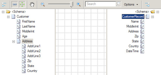
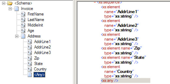
As an example, suppose that you have the following simple customer schema (Customer):
<Customer>
  <FirstName> </FirstName>
  <LastName> </LastName>
  <MiddleInit> </MiddleInit>
  <Age></Age>
  <Address>
  <AddrLine1> </AddrLine1>
  <AddrLine2> </AddrLine2>
  <AddrLine3> </AddrLine3>
  <Zip> </Zip>
  <State> </State>
  <Country></Country>
  </Address>
   </Customer>
And you want to map to another customer schema (CustomerRecord) that is slightly different in structure and format:
<CustomerRecord >
  <Name> </Name>
  <MiddleInit> </MiddleInit>
  <Address> </Address>
  <Zip> </Zip>
  <State> </State>
  <Country> </Country>
  <DateTime> </DateTime>
</CustomerRecord>
The example involves mapping values from a source to a destination schema that subsequently demonstrates different structure and invariably, message transformation. To create the BizTalk map for the example, follow these steps:
Open the project that contains the schemas.
Right-click the project, and select Add

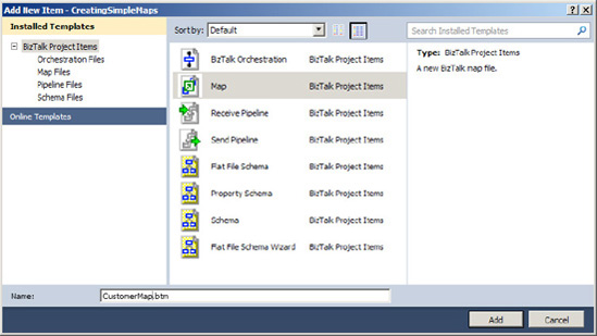
In the Add New Item dialog box, shown in Figure 3-1, click Map and give the file name a valid name. Once completed, click the Add button.
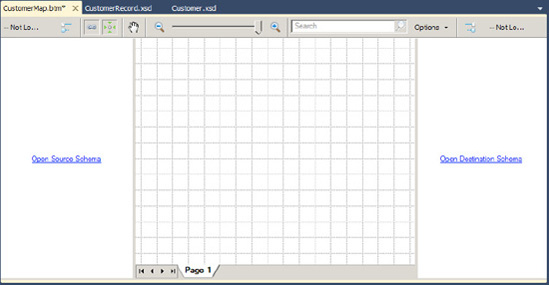
A blank map will now be opened, with left and right panes for the source and destination schema, respectively, as shown in Figure 3-2. Click the Open Source Schema link in the left pane.
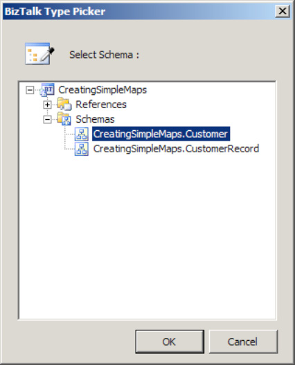
In the BizTalk Type Picker dialog box, select the
Schemastree node, and then select theCustomerschema (see Figure 3-3). Click OK.In the BizTalk Type Picker dialog box, select the
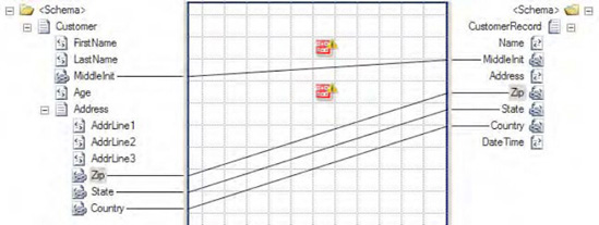
Schemastree node, select theCustomerRecordschema, and click OK. The source and destination schemas will now be displayed.Perform the straight-through mapping. Click the
MiddleInitelement in the source schema, and drag it across to theMiddleInitelement in the destination schema. Repeat this for theZip, State, andCountryelements.
Note
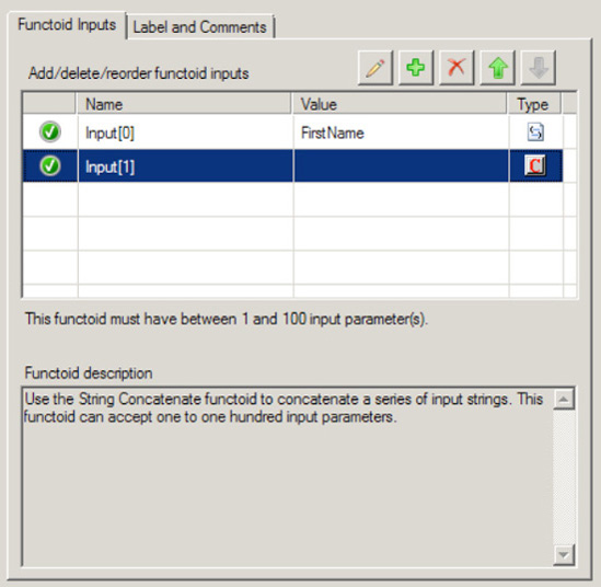
The term concatenation mapping within the BizTalk Mapper refers to the joining of two or more values to form one output value.
Here are the steps to follow in order to perform the concatenation.
In the left pane, click the Toolbox, and click the String Functoids tab.
Click and drag two String Concatenate functoids onto the map surface, as shown in Figure 3-4.
Click the
FirstNameelement in the source schema and drag it across to the left point on the first String Concatenate functoid. Click the right side of the String Concatenate functoid, and drag it across to theNameelement in the destination schema.Double-click the first String Concatenate functoid. Click the Plus button (this will add a new input), and create a constant that has a space in it (see Figure 3-5).
Click the
LastNameelement in the source schema, and drag it across to the left point on the first String Concatenate functoid. This will complete the mapping of Name.Click the
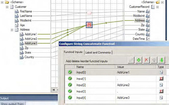
AddrLine1element in the source schema, and drag it across to the left point on the second String Concatenate functoid. Click the right side of the String Concatenate functoid, and drag it across to theAddresselement in the destination schema.Repeat step 6 for
AddrLine2andAddrLine3, adding a comma between each address field. Figure 3-6 shows the completed concatenation mapping.
To demonstrate functoid usage, you will now add a Date and Time functoid to the mapping example. In this instance, the destination schema requires a date/time stamp to be mapped. This value will be generated from the Date and Time functoid, not the source schema.
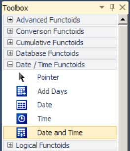
In the left pane, click the Toolbox, and then click the Date/Time Functoids tab (See Figure 3-7).
Click and drag a Date and Time functoid onto the map surface.
Click the right side of the Date and Time functoid, and drag it across to the
DateTimeelement in the destination schema.
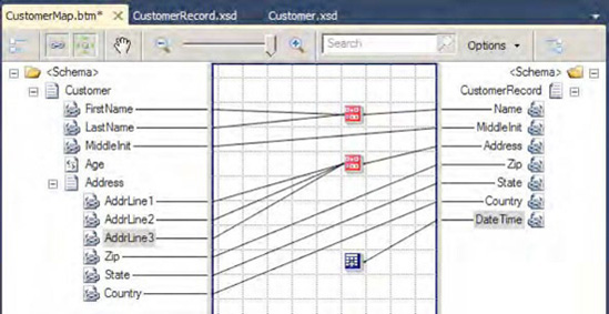
The map is now complete, as shown in Figure 3-8.
The BizTalk Mapper is used to map XML messages (instances of XML schema at runtime) to an alternate format based on transformation and/or translation. It is built on XSLT and shields the user from complex XSLT transformation logic, by providing a GUI environment to facilitate the transformation. The tool comes with numerous functoids and mapping capabilities to support straight-through and deterministic transformation. In addition, the tool gives the built-in ability to perform unit testing.
The maps created within the BizTalk Mapper environment can be used within other BizTalk runtime environments. For example, they can be used with receive/send ports, for transforming a message to and from application end points. Port mapping might be advantageous when the mapping involves minimal process considerations or the need to apply multiple maps to a given message. Changes to maps on ports can be completed without recompilation of currently deployed BizTalk assemblies. Maps can also be used with transformation shapes, for message transformation within a BizTalk orchestration. Mapping within an orchestration might be preferred when the mapping process involves broad process considerations or process support via robust exception and error handling.
The choices for where and when to map vary depending on a number of factors. A number of these have to do with common development principals (such as consistency and readability) and standards enforced by the environment in which you are operating. However, a few common rules of thumb should be noted:
Keep it simple: Keep maps logically organized. Across maps, ensure that the same look and feel are applied for consistency.
Note
Just because you can create a map using the mapper and functoids doesn't always mean you should. Make sure that whatever maps you create are simple and maintainable. Highly complex maps with many interlocking functoids can become unwieldy and next to impossible to support. Alternatives to mapping (most notably XSLT) are often very intelligent alternatives.
Keep business rules in mind: Based on the deterministic ability of mapping, be careful or keep in mind the usage of business rules within maps. If you find you are using rules within maps (for example,
If OrderTotal > $1000), keep in mind maintenance and where in your organization a decision may be made to change this rule. In addition, always consider the right place to maintain rules and context domain knowledge from an operation and support perspective.Consider performance: While mapping is powerful, complex and/or large maps can affect performance. As with all common development activities, always ensure that the logic performed is the most efficient and tested for scale in your practical operating conditions and requirements. If you experience performance issues, employ techniques such as revisiting design by exploring the solution breakdown. Consider simplifying the development task at hand.
Like all good development processes, maps should be designed and tested for desired application operation conditions.
The example in this recipe showed a baseline solution of what can be performed with the BizTalk Mapper. Throughout this chapter, other mapping capabilities will be demonstrated, illustrating the use of functoids and mapping techniques for structure and transformation control.
BizTalk Sever provides a number of features to aid in the readability and maintainability of maps. One of these features is grid pages. BizTalk Server allows you to create, name/rename, and order grid pages. When you create links between source and destination elements, the links will appear on only the selected grid page. Therefore, you can segment groups of links onto different grid pages. By default, a map file is created with one grid page named Page 1. Once you have selected source and destination schemas, you can access the grid page menu by right-clicking the tab at the bottom of the grid page, as shown in Figure 3-9.
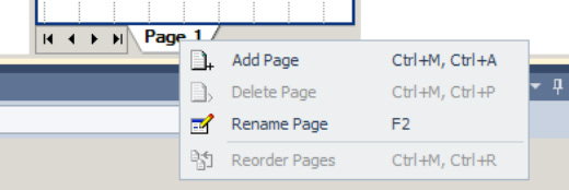
From this menu, you can perform the following functions:
Select Add Page to add a new grid page to the map.
Select Delete Page to delete the selected grid page. (If you delete a grid page, all of the links associated with that grid page will also be removed.)
Select Rename Page to rename the selected grid page.
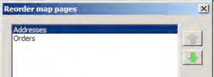
Select Reorder Pages to launch the Reorder Pages dialog box, as shown in Figure 3-10. From this dialog box, you can change the order in which the grid pages appear when viewing the map file.
Another feature provided by BizTalk Server for facilitating the readability and maintainability of maps is the ability to label links. While the labels do not appear on the grid pages, they will be used to designate the input parameters for functoids. By default, a functoid will show the XPath designation if it is linked directly to a source field, or it will show the name of the previous functoid if it is linked from another functoid. However, if the input links to a functoid are labeled, and the Label property of the link will be shown. To label a link, follow these steps:
Open the project that contains the map.
Open the map file.
Select the grid page that contains the link to be labeled.
Select the link to be labeled, right-click, and select Properties.
Fill in the
Labelproperty.
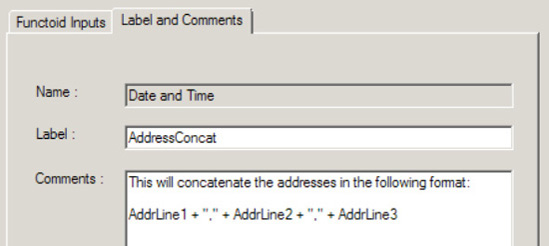
The ability to label and add comments to individual functoids is helpful in organization, especially when there are a large number of functoids on the page. To comment a functoid, simply double click the functoid, and click on the Label and Comments tab (as shown in Figure 3-11).
There are many ways to segment a map into multiple grid pages. For example, you can create a grid page for each major node in a source schema that requires complex mapping. Regardless of how you divide the map, the goal of using multiple grid pages should be to improve the readability and maintainability of the map.
You would like to use constant values within a BizTalk map. This might be because of preset output map values within a destination schema (that do not exist in the source schema) to assist in general programming concepts when using functoids, or for other reasons.
To demonstrate how to add map constants using the BizTalk Mapper, suppose that you want to use a constant in conjunction with a String Extraction functoid. In this example, you would like to extract a specified number of characters (five) from the left of the source element value. In the source schema, Customer, you have Zip elements like this:
<Zip>98103-00001</Zip>
In the destination schema, CustomerRecord, you have Zip elements like this:
<Zip>98103</Zip>
To map constants, follow these steps:
Set up the BizTalk map with the appropriate source and destination schema, as shown in Figure 3-12.
In the left pane, click the Toolbox, and then click the String Functoids tab.
Click the
Zipelement in the source schema and drag it across to the left point of the String Left functoid.Click the String Left functoid on your map surface, and select
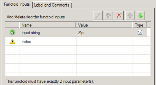
Input Parametersin the Properties window. The Configure Functoid Inputs dialog box is now displayed, as shown in Figure 3-13. Notice the first input parameter is the source schema'sZipelement. This is automatically configured as a result of dragging the sourceZipelement onto the map surface.In the Configure Functoid Inputs dialog box, click the Index row (BizTalk will automatically add required input variables).
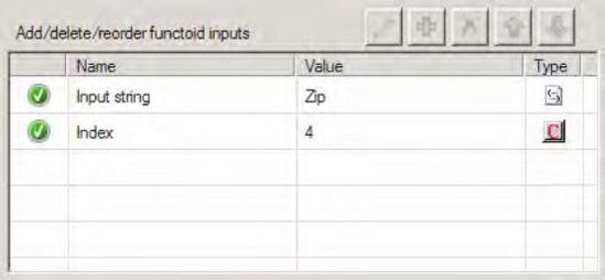
Type in the value
4. As noted, you are extracting five characters for the zip code. Because the functoid is zero-based, the start position will be 0 and the end position will be 4, resulting in five characters.Click OK to complete the functoid configuration.
Click on the right side of the String Left functoid and drag it across to the
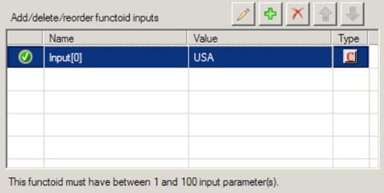
Zipelement in the destination schema.Now, drag a String Concatenate functoid onto the mapping surface. Double-click the functoid. A default input will be available; ignore this, and click the Plus button. Type the value USA. Delete the unused input (you may have to reorder using the up/down arrows). The final values should look like that shown in Figure 3-15. Click OK.
Drag the output of this new String Concatenate functoid to the Country node in the map.
You might use constant mapping for the following:
To support functoid configuration, as in the example in this recipe, which used the String Left functoid.
For values declared and assigned within a Scripting functoid. In essence, these values can be mapped as output into destination values. Furthermore, they can be declared once and accessed as global variables within other Scripting functoids in the context of the working BizTalk map.
With the String Concatenate functoid. Use the input parameter of this functoid as the constant value required. This functoid does not require any input values from the source schema. In this usage, a String Concatenate functoid would simply be mapped through to the desired destination value.
The best use of constant mapping depends on the situation and requirements you are developing against. Examine the likelihood of change within the scenario where you are looking to apply the functoid constant. If there is a high likelihood that values and their application will change, consistency should be the major factor to facilitate maintenance.
If constants are set via deterministic logic or complex or embedded business rules, it might be worth thinking about whether the constant should be applied in the map or applied within a scripting component or upstream/downstream BizTalk artifacts. The key is understanding where rules and deterministic values are set to support the specific situation. Apply the appropriate design principles to ensure the correct constant assignment technique is applied.
You might decide it would be best to map values outside the mapping environment. This could be a result of deterministic logic or business rules being the major requirement in the constants implementation. Furthermore, rules that derive constants may exist outside the BizTalk map. Constants may need to change dynamically, and it may be too cumbersome to perform a recompile/deployment for such changes within a BizTalk map.
You need to create a mapping between two schemas containing elements and attributes that are unknown when building the map, and you must include the unknown schema structures in your mapping.
You can include unknown schema structures in a map by using the <Any> element.
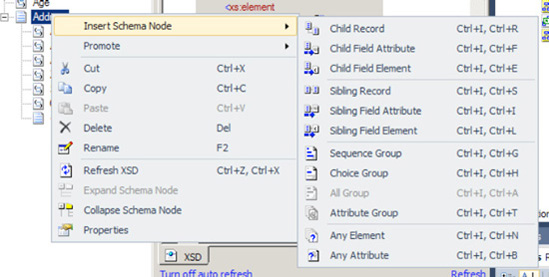
Build a source message schema containing an
<Any>element. This can be done by right-clicking the record in the schema and selecting Insert Schema NodeBuild a destination schema containing an
<Any>element, as shown in Figure 3-17.Add a new map to the solution. Set the source and target schemas appropriately.
Click the Toolbox, and then click the Advanced Functoids tab. Drag a Mass Copy functoid onto the map surface. Connect the
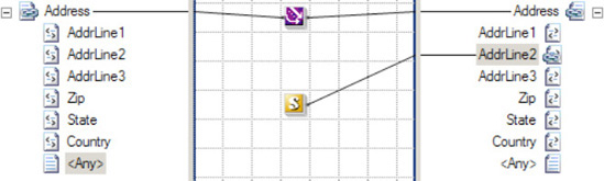
Addresselement from the source message to the Mass Copy functoid, and connect the Mass Copy functoid to theAddressfield of the destination message.Create other desired mapping links normally, as shown in Figure 3-18.
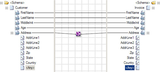
An <Any> element in a schema designates a specific location in the schema where new elements or attributes can be added. When BizTalk uses the schema to process a message containing unknown elements or attributes in the designated location, the schema will still consider the message valid. If this source message is mapped into a different schema that also has a location designated for extensibility with an <Any> element, then the information must be copied to that location with the Mass Copy functoid.
Note
By default, BizTalk will examine only the namespace and root node name of a message to identify the schema, and will not detect extra elements in the message body. To perform a deep validation of a message format, create a receive pipeline with the XML disassembler, specify the schema to validate messages against, and set Validate Document Structure to true. See Chapter 3 for more information about how to configure receive pipelines.
The contents of an <Any> element cannot be mapped with most of the default BizTalk functoids. Other functoids require establishing an explicit link from a source field, and that is not possible if the source field is not known at design time. The Mass Copy functoid can be linked only directly to an ancestor of the <Any> element, which may not give the granularity of control desired. Consider using an XSLT script with the Scripting functoid to achieve finer control. For example, if you know some element will be present at runtime but cannot predict the element name of its parent, an XSLT script can still perform the mapping.
Note that you can override the mapping of the mass copy on a line by line basis. For instance, if the Zip field needs to be mapped differently, simply add the appropriate functoid(s) and map it; this will override whatever the Mass Copy functoid has created (see Figure 3-19).
Sometimes, the BizTalk development environment has difficulty validating schemas containing <Any> elements. It can incorrectly determine that elements and attributes appearing in the location designated by the schema should not be there, causing validation for the schema to fail. This complicates schema development because the developer must deploy the schema with a pipeline capable of validating the document structure to check if the schema is correct according to a sample source message. To avoid this deployment effort while developing the schema, wait to add <Any> elements until the rest of the schema is developed and verify that those other elements are defined correctly. Then, when adding the <Any> elements to the schema, there will be a baseline of what is working correctly.
The Mass Copy functoid allows source records and containing elements and attributes to be copied and mapped across to the destination schema. This in turn, allows large structures to be mapped quickly in design time, without the need of performing 1:1 detailed mapping on all subsequent schema nodes. The Mass Copy functoid performs the recursive copying by applying a wildcard (/*) XSLT template match on source to destination XML elements. This is of particular benefit when the destination is defined as an <xs:any> type.
When mapping from source to destination, only the structure under the destination parent XML record will be copied. This often results in having to re-create the parent record element to allow all subsequent children nodes to be mapped to the destination schema. For example, consider the following two schemas, Customer and Customers:
<Customer>
  <Name> </Name>
  <AccountID> </AccountId>
  <DOB> </DOB>
</Customer>


<Customers>
  <Customer>
  <Name> </Name>
  <AccountID> </AccountId>
  <DOB> </DOB>
  </Customer>
</Customers>
In this instance, the <Customers> record cannot be mapped to the <Customer> record on the destination schema. A containing element <Customer> will need to be defined on the destination schema to enable the correct operation of the Mass Copy functoid mapping.
When mapping source to destination elements, always be cautious of underlying XSD schema rules, such as cardinality, order, and data types. For example, the Mass Copy functoid will "blindly" copy all child elements specified to the destination schema. It will not copy elements out of order or check for required values in the destination schema.
Changes to the source and destination schema may result in the need to update your impacted maps leveraging the Mass Copy functoid. This, in turn, will mandate a recompile and deployment of your BizTalk solution.
Using the Mass Copy functoid within the BizTalk Mapper is one of a variety of ways to recursively copy elements. The following are three key approaches to recursively copy XML structures:
Mass Copy functoid: Creates a wildcard XSLT template match to recursively copy elements. This approach may provide a performance benefit, as each source and destination element does not require a 1:1: XSLT template match. This, in turn, requires fewer XSLT code instructions to be interpreted and executed at runtime.
Recursive mapping: This is achieved by holding down the Shift key and mapping from a source to destination record element. This is a usability design feature that enables a developer to perform recursive mapping via one keystroke. This approach implements 1:1 XSLT template matches on all source and destination elements.
Straight-through mapping: This approach is to manually link all source and associated destination elements within the BizTalk Mapper tool. This method does 1:1 template matches on all source and destination elements.
You need to understand how and when to use the Value Mapping and the Value Mapping (Flattening) functoids.
BizTalk provides two Value Mapping functoids: Value Mapping and Value Mapping (Flattening). Both will cause a new record to be created in the destination for every record in the source. The Value Mapping (Flattening) functoid is used when the destination document has a flat structure.
Both functoids require two input parameters: a Boolean value and the node that is to be mapped. If the Boolean value is true, the value will be mapped; otherwise, it will not be mapped.
The following steps demonstrate the use of the Value Mapping functoid in a map, using the source document shown in Listing 3-1.
Example 3.1. Source Document for the Value Mapping Functoid Example
<ns0:NewHireList xmlns:ns0="http://UsingValueMappingFunctoids.NewHireList">
  <DateTime>DateTime_0</DateTime>
  <Person>
    <ID>1</ID>
    <Name>Jonesy</Name>
    <Role>.NET Developer</Role>
    <Age>47</Age>
  </Person>
  <Person>
    <ID>2</ID>
    <Name>Scott</Name>
    <Role>Database Developer</Role>
    <Age>40</Age>
  </Person>
  <Person>
    <ID>3</ID>
    <Name>Austin</Name>
    <Role>QA</Role>
    <Age>33</Age>
  </Person>
</ns0:NewHireList>
These steps refer to the Value Mapping functoid but are identical for the Value Mapping (Flattening) functoid.
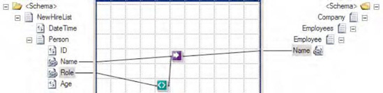
Click the Toolbox, and click the Advanced Functoids tab. Drop the Value Mapping functoid on the map surface between the source and destination schemas.
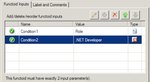
The first parameter for the Value Mapping functoid needs to be a Boolean value. For this example, a Not Equal functoid will be used to generate the Boolean value. In the Toolbox, click the Logical Functoids tab, and drop a Not Equal functoid to the left of the Value Mapping functoid. The first input parameter for the Not Equal functoid should be the value from the
Roleelement. The second input parameter should be a constant value. Set this value toQA. This will ensure that only those records that are not in this role will be mapped across. See Figure 3-20.The second parameter for the Value Mapping functoid in this example is the
Nameelement from the source document. Ensure that a line exists between this node and the functoid.Drop the output line from the Value Mapping functoid on the target node in the destination document, as shown in Figure 2-20.
At this point, the map can be tested. Using the source document shown in Listing 3-1, output of the map is the document shown in Listing 3-2.
Note
If the Value Mapping (Flattening) functoid does not map a value across, the node is not created on the destination schema, whereas if the Value Mapping functoid does not map a value, an empty destination node will be created. To change this behavior, you will need to use additional functoids or scripting.
Example 3.2. Output Document Using the Value Mapping Functoid
<ns0:Company xmlns:ns0="http://UsingValueMappingFunctoids.Company">
 <Employees>
  <Employee>
   <Name>Jonesy</Name>
  </Employee>
  <Employee>
   <Name>Scott</Name>
  </Employee>
  <Employee>
  </Employee>
 </Employees>
</ns0:Company>
If the Value Mapping functoid is replaced with the Value Mapping (Flattening) functoid (as shown in Figure 3-22), the document in Listing 3-3 will be output.
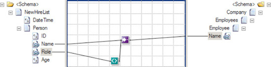
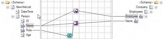
This example showed the default behavior of the Value Mapping functoid. However, the default output of the Value Mapping functoids can be altered through the use of additional functoids and scripting. For example, notice that the output in Listing 3-3 is flat instead of nested (two Person nodes within the Employee node). By adding a Looping functoid to the Name element in the source document and attaching it to the Employee root node in the destination document (see Figure 3-23), you can obtain nested output, as in Listing 3-4. The output is identical to using the Value Mapping functoid as shown in Listing 3-2.
Example 3.4. Output Using Value (Mapping) Flattening and Looping Functoids
<ns0:Company xmlns:ns0="http://UsingValueMappingFunctoids.Company">
 <Employees>
  <Employee>
   <Name>Jonesy</Name>
  </Employee>
  <Employee>
   <Name>Scott</Name>
  </Employee>
  <Employee>
  </Employee>
 </Employees>
</ns0:Company>
One of the most common situations in XML document mapping is working with nonexistent elements. By default, if an element does not exist in an incoming document but is mapped to the destination document in a BizTalk map, the node on the destination document will be created with a null value (<Node/>). The use of a Value Mapping (Flattening) functoid causes the node to be created in the destination document only if the source node exists in the source document.
You need to create a repeating structure in an output document with no equivalent repeating structure in an input document.
BizTalk Sever provides two functoids, the Table Looping functoid and the Table Extractor functoid, for creating a repeating node structure from a flattened input structure, from constant values, and from the output of other functoids. The Table Looping functoid is used to create a table of information based on inputs. The functoid will generate output for each row from this table. The Table Extractor functoid is used to direct data from each column in the table to a node in the destination document. Following are the basic steps for configuring these functoids.
Click the Toolbox, and then click the Advanced Functoids tab. Drag the functoid onto the map surface, and create links to the functoid.
Set the first input parameter, which is a link from a node structure in the input document that defines the scope of the table. If this node repeats in the input document, the number of occurrences of this element in the input document will be used to control the number of times the set of Table Extractor functoids will be invoked at runtime.
Set the second input parameter, which is a constant that defines the number of columns for each row in the table.
Set the next input parameters, which define the inputs that will be placed in the table. These inputs can come from the input document, the output from other functoids, constant values, and so on.
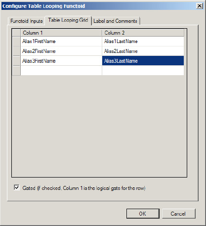
Configure the table based on inputs for the Table Looping functoid.
Select the ellipsis next to the
TableFunctoidGridproperty in the Properties window to launch the Table Looping Configuration dialog box.For each cell, select a value from the drop-down list. The drop-down list will contain a reference to all of the inputs you defined in step 1c.
Check or uncheck the Gated check box. If checked, column 1 will be used to determine whether a row in the table should be processed as follows: When the value in column 1 of the row is the output from a logical functoid, if the value is
True, the row is processed, and if the value isFalse, the row is not processed. Similarly, if the value in column 1 of the row is from a field, the presence of data equates toTrue, and the row is processed, and the absence of data equates toFalse, and the row is not processed and subsequently missing from the output structure.Select OK to close the dialog box.
Configure the outputs for the Table Looping functoid.
Link the Table Looping functoid to the repeating node structure in the output document.
Link the Table Looping functoid to a Table Extractor functoid for each column in the table. The Table Extractor functoid can be found in the Toolbox on the Advanced Functoids tab.
Configure the input parameters for each Table Extractor functoid.
Set the first input parameter, which is the output link from the Table Looping functoid.
Set the second input parameter, which is the column number of the data to be extracted from the table.
Configure the outputs for each Table Extractor functoid. Link the functoid to a node in the destination schema that is part of a repeating structure.
Note
It is very helpful to label all of the links so that meaningful names are displayed when configuring these functoids.
The Table Looping and Table Extractor functoids are used together. As an example, suppose that you have the sample input document shown in Listing 3-5.
Example 3.5. Flattened Input Structure
<AliasesFlat>
    <Names>
        <Alias1FirstName>John</Alias1FirstName>
        <Alias1LastName>Doe</Alias1LastName>
        <Alias2FirstName>Sam</Alias2FirstName>
        <Alias2LastName>Smith</Alias2LastName>
        <Alias3FirstName>James</Alias3FirstName>
        <Alias3LastName>Jones</Alias3LastName>
    </Names>
</AliasesFlat>
The goal is to use these two functoids to create an output document of the format shown in Listing 3-6.
Example 3.6. Repeating Nested Structure
<AliasesRepeating>
<AliasNames>
<FirstName>John</FirstName>
<LastName>Doe</LastName>
</AliasNames>
<AliasNames>
<FirstName>Sam</FirstName>
<LastName>Smith</LastName>
</AliasNames>
<AliasNames>
<FirstName>James</FirstName>
<LastName>Jones</LastName>
</AliasNames>
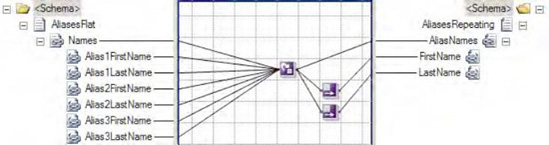
</AliasesRepeating>Figure 3-24 shows the configuration for the input parameters for the Table Looping functoid. The first parameter is a reference to the node structure Names in the input schema. The second parameter is a constant value of 2 indicating there will be two columns in the table. The remaining parameters are the first and last name of each alias from the input document.
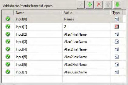
Figure 3-25 shows the completed Table Looping Configuration dialog box for the Table Looping functoid. It has been configured so that each row contains an alias first name in column 1 and an alias last name in column 2. There will be three rows in the table to process, one for each alias provided as input.
The output links from the Table Looping functoid are configured as follows:
Figure 3-26 shows the configuration for the Table Extractor functoid that will process column 1 from the table. The first parameter is a link from the Table Looping functoid, and the second parameter is a constant value of 1, which indicates it will process the first column from each row as it is processed.
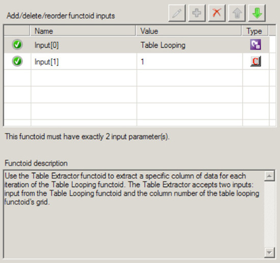
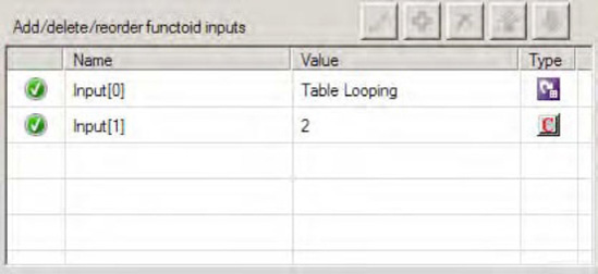
Figure 3-27 shows the configuration for the Table Extractor functoid that will process column 2 from the table. The first parameter is a link from the Table Looping functoid, and the second parameter is a constant value of 2, which indicates it will process the second column from each row as it is processed.
Finally, each Table Extractor functoid must be linked to a node in the destination schema. The complete map is shown in Figure 3-28.
Here is what the data table will look like when the map is processed:
Column 1 | Column 2 |
|---|---|
John | Doe |
Sam | Smith |
James | Jones |
Once the table is loaded, it will generate three sets of output: one set of output for each row in the table. This, in turn, will create three repetitions of the AliasNames node structure in the destination document: one for each row in the table. A repeating node structure has been created, even though one did not exist in the input document.
You need to map an incoming node to a database table column to reference a specific set of data via a BizTalk Server map. Specifically, for an inbound author ID, you need to retrieve the person attributes that are stored in a SQL based table. Additionally, the data that is stored in the database table is dynamic, and coding the values within the BizTalk map is not possible.
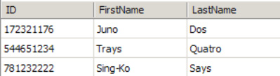
BizTalk provides the Database Lookup functoid, which can retrieve a recordset. For example, suppose that the inbound message specifies an author's Social Security number but no personal information. The map must retrieve the author's information and map the information to the outbound message. The Database Lookup functoid can retrieve the information from a specific SQL table using the author's Social Security number as the value for which to search. The inbound XML message may have a format similar to the following and a table with data as show in Figure 3-29.
<ns0:PersonSearch xmlns:ns0="http://DatabaseLookupFunctoid.PersonSearch">
  <ID>172321176</ID>
</ns0:PersonSearch>
You can use the Database Lookup functoid by taking the following steps:
Click the Toolbox, and then click the Database Functoids tab. On the map surface, in between the source and destination schemas, drag and drop a Database Lookup functoid.
Connect the left side of the Database Lookup functoid to the inbound document node that will specify the value used in the search.
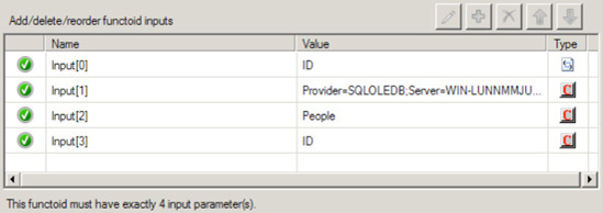
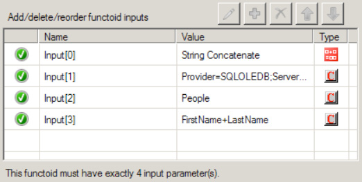
Configure the input parameters of the Database Lookup functoid, as shown in Figure 3-30. This functoid requires four parameters to be specified either through mapping the inbound source data to the functoid or through setting constants in the functoid.
For the first input parameter, verify that the inbound node, connected in step 2, is the first value in the list of properties. This is a value to be used in the search criteria. It's basically the same as the value used in a SQL
WHEREclause.Set the second parameter, which is the connection string for the database. The connection string must be a full connection string with a provider, machine name, database, and either account/password or a flag indicating the use of Trusted Security mode in SQL. The connection string must include a data provider attribute. A lack of data provider attribute will generate a connection error when the map tries to connect to the database.
Note
The easiest connection string to start with is integrated security, which has the format of
Provider=SQLOLEDB;Server=[servername];Database=[dbname];Integrated Security=SSPI;.Set the third parameter, which is the name of the table used in search.
Set the fourth parameter, which is the name of the column in the table to be used in search.
Again, click the Toolbox, and click the Database Functoids tab. On the map surface, after the Database Lookup functoid, drag and drop the Error Return functoid.
Connect the right side of the Database Lookup functoid to the left side of the Error Return functoid. Connect the right side of the Error Return functoid to the outbound schema node that is a placeholder for error messages.
Again, click the Toolbox, and click the Database Functoids tab. On the map surface, above the Error Return functoid, drag and drop the Value Extractor functoid for each extracted value from the return recordset. For example, if you are returning five values in the recordset, you would need five Value Extractor functoids.
For each Value Extractor functoid, connect the left side of the functoid to the right side of the Database Lookup functoid.
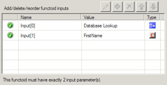
Configure the properties of each Value Extractor functoid to retrieve the appropriate value by specifying the column name of the extracted value. For example, if the value returned resides in a column named
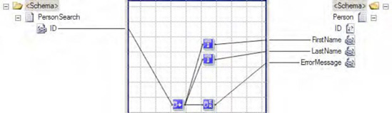
FirstName, you would create a constant in the Value Extractor functoid namedFirstName. The Value Extractor functoid's Configure Functoid Inputs dialog box should look similar to Figure 3-31.For each Value Extractor functoid, connect the right side of the functoid to the appropriate target schema outbound node. The completed map should look similar to the sample map in Figure 3-32.
The Database Lookup functoid requires four parameters as inputs, and it outputs an ActiveX Data Objects (ADO) recordset. Keep in mind that the recordset returns only the first row of data that matches the specific criteria provided to the Database Lookup functoid.
In addition to the input parameters, the Database Lookup functoid requires two helper functoids for optimal use:
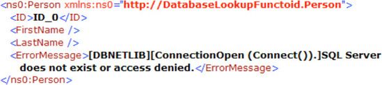
The Error Return functoid, which returns SQL-related errors or exceptions. The Error Return functoid requires the Database Lookup functoid as the input and a link to an output node in the target schema. To avoid runtime errors, verify that the only inbound connection to the Error Return functoid is that of the Database Lookup functoid and not any other database functoids. A generated error looks like that shown in Figure 3-33.
The Value Extractor functoid, which retrieves a specific column from the returned recordset. The Value Extractor will retrieve the value based on the specific column specified in the input parameters.
Whenever you use SQL authentication (SQL username and password), there is potential for a security risk. Consider using trusted security for access to the database rather than specifying the username and password in the connection string used by the Database Lookup functoid. For example, here is a connection string that uses SQL security:
Provider=SQLOLEDB;Server=localhost;Database=pubs;User ID=sa;Password=password;
  Trusted_Connection=False
And here is an example of a connection string that uses Trusted Security:
Provider=SQLOLEDB;Server=localhost;Database=pubs;Integrated Security=SSPI;
Keep in mind that if you choose Trusted Security for authentication, the account under which the BizTalk host instance is running must have appropriate access to the SQL Server, the SQL database, and the table in which the Database Lookup functoid is looking.
Another option to enclosing connection string information within the Database Lookup functoid is to make use of a Universal Data Link (UDL) file. A UDL is simply a text file with the file extension .udl. The connection string is included within the UDL file, and the connection string parameter in the Database Lookup functoid becomes a reference to that file, for example:
File Name=c:BizTalkConfigConnectionString.UDL
Once the UDL file is created, it can be made available on a secure file share.
Note
UDL files are external to the BizTalk map and therefore must be parsed every time a connection to the database is open. The parsing activity will cause some performance degradation.
Additionally consider the use of a SQL view, versus direct table access, and having the Database Lookup functoid point to the database view. A SQL view offers the ability to manage table security permissions or the abstraction of the physical table structure.
The Database Lookup functoid is convenient to implement in mappings. For straightforward data retrieval, this functoid performs adequately. However, the following items should be taken into consideration when evaluating when to use the Database Lookup functoid:
Database availability: If you cannot guarantee that the data source being queried will be available when BizTalk is available, using the Database Lookup functoid may not make sense.
Error management: Mapping will occur and not trap the SQL errors in the .NET exception style. Errors should be trapped and managed when mapping. When implementing the Database Lookup functoid, consider using the Error Return functoid. Additionally, after the mapping, it would be wise to query the
Error Returnnode for an error message and implement error handling if one exists.Performance: Evaluate your performance requirements and determine if accessing a SQL database will negatively affect your overall mapping performance. Implementing the Database Lookup functoid may not impact performance greatly, but consider the effect if you must run the Database Lookup functoid multiple times in a single map. Database Lookup functoids that are part of a looping structure will cause a level of performance degradation. Make sure that the latest BizTalk service packs are applied when using the Database Lookup functoid, as they include performance-enhancing features such as caching.
Database support: Evaluate if the database that you must access will support the necessary security requirements and also allow table (or at least view level) access.
The BizTalk map translates the Database Lookup functoid information into a dynamic SQL SELECT statement. If you run a SQL Profiler trace during testing of the BizTalk map, you will see the SELECT call with the dynamic SQL. Knowing that dynamic SQL is created by the Database Lookup functoid allows you to use it to perform some relatively powerful database lookups. The Database Lookup functoid allows only a single value and single column name to be referenced in the query. However, with a bit of extra mapping, you can use this functoid to query against multiple columns. The map in Figure 3-32 generates the following SQL query code:
exec sp_executesql N'SELECT * FROM people WHERE ID= @P1', N'@P1 nvarchar(9)',
N'172321176'
This query performs a SELECT to retrieve all rows from the People table where the author ID is equal to the value in the inbound XML document (for example, 172321176).
Keep in mind that the Database Lookup functoid returns only the first row that it encounters in the recordset. If multiple authors had the same ID, you would potentially retrieve the incorrect author. For example, if the author ID is the last name of the author, you may retrieve multiple authors that share the same last name. One way to ensure uniqueness, aside from querying on a unique column, is to specify additional columns in the query. The Database Lookup functoid accepts only four parameters, so additional concatenation must occur before submitting the parameters to the Database Lookup functoid.
After configuring the inbound concatenated value, the next step is to specify multiple column names as the input parameter in the Database Lookup functoid. Figure 3-34 demonstrates a sample Database Lookup functoid configuration with multiple columns specified. The output from the Database Lookup functoid to the Value Extractor functoid does not change.
Note
A plus symbol (+) is used between the column names in the Database Lookup functoid, whereas in the Concatenation functoid, no + is required. If a + is specified in the Concatenation functoid, you will receive incorrect results, as the dynamic SQL statement created will be incorrect.
In this example, the inbound message specifies an author's first name and last name instead of a unique author ID. The map must still retrieve the author's information and map the information to the outbound message. The inbound XML message may have a format to the following message:
<ns0:PersonSearch xmlns:ns0="http://DatabaseLookupFunctoid.PersonSearch">
  <FirstName>Juan</FirstName>
  <LastName>Dos</LastName>
</ns0:PersonSearch>
The following is the dynamic SQL created in the map that accepts multiple columns:
exec sp_executesql N'SELECT * FROM authors WHERE FirstName+LastName= @P1', N'@P1
nvarchar(12)', N'JuanDos'
The dynamic SQL created shows the inbound author's first name and last name parameters as a concatenated parameter. The SQL statement also shows a combination WHERE clause with FirstName + LastName.
There are some limitations to specifying multiple columns through the concatenation approach. Specifically, string data types are the only data types that work reliably due to the concatenation operation that occurs in SQL. Integer data types may also be used, but in the case of integer (or other numeric data types), SQL will perform an additive operation versus a concatenation operation. Adding two numbers together, as what would happen when specifying numeric data types, and comparing the result to another set of numbers being added together may yield multiple matches and may not achieve the desired results. The mix of varchar and numeric fields will not work with this approach, as you will receive a data casting exception from your data provider.
You wish to dynamically cross-reference unique identifiers between two or more systems. The reference data already exists, so you wish to load the data into the BizTalk cross-reference tables before you use the cross-reference functoids or application programming interface (API).
Within an XML configuration file you name List_Of_App_Type.xml, insert the XML shown in Listing 3-7, and insert an appType node for each system that will have cross-references.
Example 3.7. List_Of_App_Type.xml
<?xml version="1.0" encoding="UTF-8"?>
<listOfAppType>
    <appType>
        <name>Oracle</name>
        <description/>
    </appType>
    <appType>
        <name>Siebel</name>
        <description/>
    </appType>
</listOfAppType>
Note
These node values in Listings 3-7 through 3-10 have been placed in the XML as an example. You should remove them and insert your own.
Within an XML configuration file you name List_Of_App_Instance.xml, insert the XML shown in Listing 3-8.
Example 3.8. List_Of_App_Instance.xml
<?xml version="1.0" encoding="UTF-8"?>
<listOfAppInstance>
        <appInstance>
            <instance>Oracle_01</instance>
            <type>Oracle</type>
            <description/>
        </appInstance>
        <appInstance>
            <instance>Siebel_01</instance>
            <type>Siebel</type>
            <description/>
        </appInstance>
        <appInstance>
            <instance>Siebel_12</instance>
            <type>Siebel</type>
            <description/>
        </appInstance>
</listOfAppInstance>
Since unique identifiers are often different for each unique instance of a system, you must create different cross-references for each system. Therefore, you must insert an appInstance node for each instance of an application you will cross-reference, inserting a common type value across instances that are of the same type of system, and which correspond to the appType you created in the List_Of_App_Type.xml configuration file. For instance, you may be running two instances of Siebel, so you would insert two appInstance nodes with a type of Siebel, but give each a unique value in the instance node (for example, Siebel_01 and Siebel_12).
Within an XML configuration file you name List_Of_IdXRef.xml, insert the XML shown in Listing 3-9.
Example 3.9. List_Of_IdXRef.xml
<?xml version="1.0" encoding="UTF-8"?>
<listOfIDXRef>
    <idXRef>
        <name>Customer.ID</name>
        <description/>
    </idXRef>
    <idXRef>
        <name>Order.PONumber</name>
        <description/>
    </idXRef>
</listOfIDXRef>
For each ID field you plan to cross-reference, insert an idXRef node with a unique name child node. This value will be used to identify the ID field that you are cross-referencing. For instance, if you plan to cross-reference a customer that is in different systems, you would insert an idXRef with a name like Customer.ID.
Within an XML configuration file you name List_Of_IdXRef_Data.xml, insert the XML shown in Listing 3-10.
Example 3.10. List_Of_IdXRef_Data.xml
<?xml version="1.0" encoding="UTF-8"?>
<listOfIDXRefData>
    <idXRef name="Customer.ID">
        <appInstance name="Oracle_01">
            <appID commonID="100"> CARA345</appID>
        </appInstance>

        <appInstance name="Siebel_01">
            <appID commonID="100">99-4D976</appID>
        </appInstance>
        <appInstance name="Siebel_12">
            <appID commonID="100">44OL</appID>
        </appInstance>
    </idXRef>
</listOfIDXRefData>
For each field you create in the List_Of_IdXRef.xml file, insert an idXRef node. For each system you create in the List_Of_App_Instance.xml file, insert an appInstance node. Insert one or more appID nodes for each unique identifier. Insert a commonID attribute to store a common identifier, and set the application-specific value within the node. The common ID will be repeated for each appID that is cross-referenced.
Within an XML configuration file you name Setup-Config.xml, insert the XML shown in Listing 3-11.
Example 3.11. Setup-Config.xml
<?xml version="1.0" encoding="UTF-8"?>
<Setup-Files>
    <App_Type_file>C:List_Of_App_Type.xml</App_Type_file>
    <App_Instance_file>C:List_Of_App_Instance.xml</App_Instance_file>
    <IDXRef_file>C:List_Of_IDXRef.xml</IDXRef_file>
    <IDXRef_Data_file>C:List_Of_IDXRef_Data.xml</IDXRef_Data_file>
</Setup-Files>
Each node should point to the physical location where you have created the corresponding XML configuration files.
Seed the BizTalk cross-reference tables by opening a command-line window and running the BizTalk cross-reference import tool, BTSXRefImport.exe (found in the BizTalk installation directory), passing in the path to the cross-reference XML file created in Listing 3-11:
BTSXRefImport.exe -file=C:Setup-Config.xml
During installation of BizTalk, several cross-reference tables are created in the BizTalkMgmtDb database. All the cross-reference tables begin with the prefix xref_, and the BTSXRefImport tool imports the data from the XML files provided into the table structure for access at runtime. It is not necessary to use the BTSXRefImport.exe tool to insert data into the cross-reference tables. You may insert data directly into the following tables:
xref_AppInstancexref_IdXRefxref_IdXRefData
After running the BTSXRefImport tool, and if the data were in a denormalized form, the data would look like this:
AppType | AppInstance | IdXRef | CommonID | Application ID |
|---|---|---|---|---|
Oracle | Oracle_01 | Customer.ID | 100 | CARA345 |
Siebel | Siebel_01 | Customer.ID | 100 | 99-4D976 |
Siebel | Siebel_12 | Customer.ID | 100 | 44OL |
There are subtle differences between ID and value cross-referencing. Value cross-references, as the name implies, deal with static values, while ID cross-references deal with cross-referencing unique identifiers. Since most value cross-references are not updated at runtime, a functoid and API method are not provided to update the references at runtime. ID cross-references, though, may be updated using the Set Common ID functoid or API method.
Note
The Set Common ID functoid is poorly named, as it actually sets the application ID and the CommonID. If CommonID is not provided, the method will return a new CommonID Instance.
You wish to statically cross-reference state values between two or more systems. The reference data already exists, but you must load the data into the BizTalk cross-reference tables before you may use the cross-reference functoids or API.
Within an XML configuration file you name List_Of_App_Type.xml, insert the XML shown in Listing 3-12, and insert an appType node for each system that will have static cross-references.
Example 3.12. List_Of_App_Type.xml
<?xml version="1.0" encoding="UTF-8"?>
<listOfAppType>
    <appType>
        <name>Oracle</name>
        <description/>
    </appType>
    <appType>
        <name>Siebel</name>
        <description/>
    </appType>
</listOfAppType>
Note
The node values in Listings 3-12 through 3-14 have been placed in the XML as an example. You should remove them and insert your own.
Within an XML configuration file you name List_Of_ValueXRef.xml, insert the XML shown in Listing 3-13.
Example 3.13. List_Of_ValueXRef.xml
<?xml version="1.0" encoding="UTF-8"?>
<listOfValueXRef>
    <valueXRef>
        <name>Order.Status</name>
        <description/>
    </valueXRef>
</listOfValueXRef>
For each field you plan to statically cross-reference, insert a valueXRef node with a unique child node name. This value will be used to identify the static field. For instance, if you plan to map between order status codes, you might create a common value of Order.Status.
Within an XML configuration file you name List_Of_ValueXRef_Data.xml, insert the XML shown in Listing 3-14.
Example 3.14. List_Of_ValueXRef_Data.xml
<?xml version="1.0" encoding="UTF-8"?>
<listOfValueXRefData>
<valueXRef name="Order.Status">
    <appType name="Oracle">
        <appValue commonValue="Open">OP</appValue>
        <appValue commonValue="Pending">PD</appValue>
        <appValue commonValue="Closed">CD</appValue>
    </appType>
    <appType name="Siebel">
        <appValue commonValue="Open">1:Open</appValue>
        <appValue commonValue="Pending">2:Pending</appValue>
        <appValue commonValue="Closed">3:Closed</appValue>
    </appType>
</valueXRef>
</listOfValueXRefData>
For each static field you create in the List_Of_ValueXRef.xml file, insert a valueXRef node. For each system you create in the List_Of_App_Type.xml file, insert an appType node. Insert one or more appValue nodes for each value that is permissible for this valueXRef field. Insert a commonValue attribute to store the common name for the value, and set the application-specific value within the node. The common value will be repeated for each appType that is cross-referenced.
Within an XML configuration file you name Setup-Config.xml, insert the XML shown in Listing 3-15.
Example 3.15. Setup-Config.xml
<?xml version="1.0" encoding="UTF-8"?>
<Setup-Files>
<App_Type_file>c:List_OF_App_Type.xml</App_Type_file>
<ValueXRef_file>c:List_Of_ValueXRef.xml</ValueXRef_file>
<ValueXRef_Data_file>c:List_Of_ValueXRef_Data.xml</ValueXRef_Data_file>
</Setup-Files>
Each node should point to the physical location where you have created the corresponding XML configuration files.
Seed the BizTalk cross-reference tables by opening a command-line window and running the BizTalk cross-reference import tool, BTSXRefImport.exe (found in the BizTalk installation directory), passing in the path to the Setup-Config.xml cross-reference file:
BTSXRefImport.exe -file=C:Setup-Config.xml
During installation of BizTalk, several static cross-reference tables are created in the BizTalkMgmtDb database. All the cross-reference tables begin with the prefix xref_, and the BTSXRefImport tool imports the data from the XML files provided to the table structure for access at runtime. It is not necessary to use the BTSXRefImport.exe tool to insert data into the cross-reference tables. You may insert data directly into the following tables:
xref_AppTypexref_ValueXRefxref_ValueXRefData
In a denormalized form, the table would look like this after running the BTSXRefImport tool:
AppType | ValueXRef | CommonValue | AppValue | AppType |
|---|---|---|---|---|
Oracle | Order.Status | Open | OP | Oracle |
Siebel | Order.Status | Open | 1:Open | Siebel |
Oracle | Order.Status | Pending | PD | Oracle |
Siebel | Order.Status | Pending | 2:Pending | Siebel |
Oracle | Order.Status | Closed | CD | Oracle |
Siebel | Order.Status | Closed | 3:Closed | Siebel |
Within a map, you wish to dynamically cross-reference unique identifiers between two or more systems, and the identifier cross-references have already been loaded into the cross-reference tables. For example, a source system publishes an Account with a unique identifier of 1234, and you want to cross-reference and dynamically translate that identifier to the unique identifier in a destination system of AA3CARA.
Note
If you have not already loaded the identifier cross-reference data, see Recipe 3-8 for more information.
To cross-reference the identifiers within a map, take the following steps:
Click the Database Functoids tab in the Toolbox.
Drag the Get Common ID functoid onto to the map surface.
Open the Input Parameters dialog box for the Get Common ID functoid.
Add a constant parameter and set the value to the ID type you wish to cross-reference. For instance, you may set the value to something like
Customer.ID.Add a second constant parameter to the Get Common ID functoid, and set the value to the source system application instance. For instance, you may set the value to something like
Siebel_01.Click OK.
Connect the unique source identifier node you wish to cross-reference from the source schema to the Get Common ID functoid.
Drag the Get Application ID functoid from the Database Functoids tab onto the map surface, and place it to the right of the Get Common ID functoid.
Open the Input Parameters dialog box for the Get Application ID functoid.
Add a constant parameter and set the value to the ID type you wish to receive. For instance, you may set the value to something like
Customer.ID.Add a second constant parameter to the Get Common ID functoid and set the value to the destination system application instance. For instance, you may set the value to something like
Oracle_01.Click OK.
Connect the Get Common ID functoid to the Get Application ID functoid.
Connect the functoid to the unique destination identifier node.
Save and test the map.
Identifier cross-referencing allows entities to be shared across systems. Although cross-referencing functionality is often not required in small integration projects, as usually there is a single system for a given entity type, in larger organizations, it is common to find several systems with the same entities (for example, Account, Order, and Invoice). These entities are often assigned a unique identifier that is internally generated and controlled by the system. In other words, from a business perspective, the entities are the same, but from a systems perspective, they are discrete. Therefore, in order to move an entity from one system to another, you must have a way to create and store the relationship between the unique identifiers, and to discover the relationships at runtime.
BizTalk Server provides this functionality through cached cross-referencing tables, API, an import tool, and functoids. Using the import tool, you can load information about systems, instances of those systems, the entities within those systems you wish to cross-reference, and the actual cross-reference data into a set of cross-reference tables that are installed with BizTalk in the BizTalkMgmtDb database. Then, using the functoids or API at runtime, you access the tables to convert an identifier from one recognized value to another. The basic steps for converting from one system to another are as follows:
Using the source identifier, source instance, and source entity type, retrieve the common identifier by calling the Get Common ID functoid.
Note
The common identifier is commonly not stored in any system. It is an identifier used to associate one or more identifiers.
Using the common identifier, destination system instance, and destination entity type, retrieve the destination identifier by calling the Get Application ID functoid.
This recipe has focused on accessing identifier cross-referencing functionality through BizTalk functoids, but an API is also available. The cross-referencing class may be found in the Microsoft.Biztalk.CrossRreferencing.dll, within the namespace Microsoft.BizTalk.CrossReferencing. This class has several members that facilitate storing and retrieving identifier cross referencing relationships, as listed in Table 3-1.
Table 3.1. ID Cross-Referencing API
Member | Description |
|---|---|
| With an application instance, entity/ID type, and application identifier value, retrieves a common identifier. If a cross-reference does not exist, a blank will be returned. If the application instance or entity/ID type does not exist, an exception will be thrown. |
| With a common identifier, application instance, and entity/ID type, retrieves the application identifier value. If a cross-reference does not exist, a blank will be returned. If the application instance or entity/ID type does not exist, an exception will be thrown. |
| With an application instance, entity/ID type, application identifier value, and optionally a common identifier, create a relationship in the cross-referencing tables. If a common identifier is not passed to the method, one will be created and returned. If the application instance or entity/ID type does not exist, an exception will be thrown. |
[a] The | |
Within a map, you wish to statically cross-reference state values between two or more systems, and the value cross-references have already been loaded into the cross-reference tables. For example, a source system publishes an Order with a status of 1:Open, and you want to cross reference and translate the static state value to the static value in a destination system of OP.
Note
If you have not already loaded the value cross-reference data, see Recipe 3-9 for more information.
To cross-reference the static values within a map, take the following steps:
Drag the Get Common Value functoid to the map surface.
Open the Input Parameters dialog box for the Get Common Value functoid.
Add a constant parameter, and set the value to the static value type you wish to cross-reference. For instance, you may set the value to something like
Order.Status.Add a second constant parameter to the Get Common Value functoid, and set the value to the source system application type. For instance, you may set the value to something like
Siebel.Click OK.
Connect the state value source node you wish to cross-reference from the source schema to the Get Common Value functoid.
Drag the Get Application Value functoid from the Database Functoids tab to the map surface, and place it to the right of the Get Common Value functoid.
Open the Input Parameters dialog box for the Get Application Value functoid.
Add a constant parameter, and set the value to the static value type you wish to cross-reference. For instance, you may set the value to something like
Order.Status.Add a second constant parameter to the Get Common Value functoid, and set the value to the destination system application type. For instance, you may set the value to something like
Oracle.Click OK.
Connect the Get Common Value functoid to the Get Application Value functoid.
Connect the functoid to the unique destination state value node.
Save and test the map.
Identifier and value cross-referencing are similar in concept, with the following differences:
Value cross-referencing is commonly between enumeration fields. Identifier cross-referencing is commonly between entity unique identifiers.
Value cross-referencing occurs between system types. Identifier cross-referencing occurs between instances of system types.
Identifier cross-references may be set at runtime. Value cross-references are static and may be loaded only through the import tool or direct table manipulation.
The basic steps for converting from one system to another are as follows:
Using the source application type, source application static value, and source entity value type, retrieve the common value by calling the Get Common Value functoid.
Note
The common value is generally not stored in any system. It is a value used to associate multiple values.
Using the common static value, destination system type, and destination entity value type, retrieve the destination static value by calling the Get Application Value functoid.
This recipe has focused on accessing value cross-referencing functionality through BizTalk functoids, but an API is also available. The cross-referencing class may be found in the Microsoft.Biztalk.CrossRreferencing.dll, within the namespace Microsoft.BizTalk.CrossReferencing. This class has several members that facilitate storing and retrieving value cross-referencing relationships, as listed in Table 3-2.
Table 3.2. Value Cross-Referencing API
Member | Description |
|---|---|
| With an application type, entity/node value type, and application value, this member retrieves a common value. If a cross-reference does not exist, a blank will be returned. If the application type or entity/node value type does not exist, an exception will be thrown. |
| With a common value, application type, and entity/node type, this retrieves the application value. If a cross-reference does not exist, a blank will be returned. If the application type or entity/node value type does not exist, an exception will be thrown |
The structure of a message from a source system you are integrating with contains multiple repeating record types. You must map each of these record types into one record type in the destination system. In order for the message to be imported into the destination system, a transformation must be applied to the source document to consolidate, or standardize, the message structure.
Create a map that utilizes the BizTalk Server Looping functoid, by taking the following steps:
Click the Toolbox, and then click the Advanced Functoids tab. On the map surface, between the source and destination schemas, drag and drop a Looping functoid. This functoid accepts 1 to 100 repeating source records (or data elements) as its input parameters. The return value is a reference to a single repeating record or data element in the destination schema.
Connect the left side of the Looping functoid to the multiple repeating source data elements that need to be consolidated.
Connect the right side of the Looping functoid to the repeating destination data element that contains the standardized data structure.
An example of a map that uses the Looping functoid is shown in Figure 3-35.
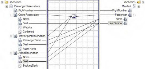
In this example, multiple types of plane flight reservations are consolidated into a single list of records capturing passengers and their associated seats. The XML snippet in Listing 3-16 represents one possible instance of the source schema.
Example 3.16. Source Schema Instance for the Looping Functoid Example
<ns0:PassengerReservations xmlns:ns0="http://LoopingFunctoid.PassengerReservations">
  <FlightNumber>666</FlightNumber>
  <OnlineReservation>
    <Name>Lucifer Smith</Name>
    <Seat>13A</Seat>
    <Website>www.greatdeals.com</Website>
    <Confirmed>True</Confirmed>
  </OnlineReservation>
  <OnlineReservation>
    <Name>Beelzebub Walker, Jr.</Name>
    <Seat>13B</Seat>
    <Website>www.hellofadeal.com</Website>
    <Confirmed>False</Confirmed>
  </OnlineReservation>
  <TravelAgentReservation>
    <PassengerName>Jim Diablo</PassengerName>
    <Seat>13C</Seat>
    <AgentName>Sunny Rodriguez</AgentName>
  </TravelAgentReservation>
  <AirlineReservation>
    <Name>Imin Trouble</Name>
    <Seat>13D</Seat>
    <BookingDesk>Chicago</BookingDesk>
  </AirlineReservation>
</ns0:PassengerReservations>
Based on this source XML, the looping map displayed in Figure 3-35 will produce the XML document shown in Listing 3-17, containing a single passenger seat assignment list.
Example 3.17. Destination Schema Instance for the Looping Functoid Example
<ns0:Manifest FlightNumber="666" xmlns:ns0="http://LoopingFunctoid.Manifest">
  <Passenger Name="Lucifer Smith" SeatNumber="13A" />
  <Passenger Name="Beelzebub Walker, Jr." SeatNumber="13B" />
  <Passenger Name="Jim Diablo" SeatNumber="13C" />
  <Passenger Name="Imin Trouble" SeatNumber="13D" />
 </ns0:Manifest>
This example displays a simplistic but useful scenario in which the Looping functoid can be used. Essentially, this functoid iterates over the specified repeating source records (all those with a link to the left side of the functoid), similar to the For...Each structure in coding languages, and maps the desired elements to a single repeating record type in the destination schema.
Note
The four source records in the XML instance (the two OnlineReservations records, the one TravelAgentReservation record, and the one AirlineReservation record) produced four records in the output XML. If the source instance had contained five records, the resulting output XML document would also contain five records.
Based on this simple principle, you can develop much more complex mappings via the Looping functoid. One example of a more advanced use of the Looping functoid is conditional looping. This technique involves filtering which source records actually create destination records in the resulting XML document. The filtering is done by adding a logical functoid to the map, which produces a true or false Boolean value based on the logic. Common examples of filtering are based on elements that indicate a certain type of source record, or numeric elements that posses a certain minimum or maximum value.
The previous flight reservation example can be extended to implement conditional looping, in order to map only those online reservations that have been confirmed. This can be accomplished via the following steps:
Click the Toolbox, and click the Logical Functoids tab. On the map surface, in between the source and destination schemas, drag and drop a logical Equal functoid. This functoid accepts two input parameters, which are checked for equality. The return value is a Boolean
trueorfalse.Specify the second input parameter for the logical Equal functoid as a constant with a value of
True.Connect the left side of the logical Equal functoid to the data element whose value is the key input for the required decision (Confirmed in the
OnlineReservationnode, in this case) logic.Connect the right side of the logical Equal functoid to the element in the destination schema containing the repeating destination data element that contains the standardized data structure.
An example of the enhanced map is shown in Figure 3-36.
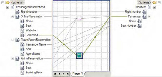
Based on the same source XML outlined earlier in Listing 3-16, the looping map displayed in Figure 3-36 will produce the following XML document, containing a single passenger seat assignment list with only three passengers (Lauren Jones's reservation, which was not confirmed, is filtered out by the conditional looping logic):
<ns0:Manifest FlightNumber="666" xmlns:ns0="http://LoopingFunctoid.Manifest">
  <Passenger Name="Lucifer Smith" SeatNumber="13A" />
  <Passenger Name="Jim Diablo" SeatNumber="13C" />
  <Passenger Name="Imin Trouble" SeatNumber="13D" />
 </ns0:Manifest>
Note
Due to the fact that the Confirmation element is not being mapped over to the destination schema, the output of the logical Equal functoid is tied to the Passenger record. If the logical Equal functoid were being applied to an element that is being mapped to the destination schema, such as the Seat element, the output of the Equal functoid could be tied directly to the SeatNumber element in the destination schema.
In this example of conditional looping, the second input parameter of the logical Equal functoid is a hard-coded constant set to True. In real-world scenarios, it may not be ideal for this value to be hard-coded. You may prefer to have it driven off a configurable value. Several alternatives exist:
Implement a Scripting functoid to the map, which passes the name of a configuration value to an external assembly. This external assembly would then handle the lookup of the actual configuration value.
Implement a Database Lookup functoid, which as the name implies, would look up the appropriate configuration value from a database table.
Use a custom functoid, written in any .NET-compliant language. This option is similar to the external assembly route, except that it is implemented specifically as a functoid as opposed to a general .NET assembly.
When implementing a map that uses the Looping functoid, it is important to understand how BizTalk Server inherently handles repeating records in the source schema. If a record in the source schema has a Max Occurs property set to a value greater than 1, BizTalk Server handles the record via a loop. No Looping functoid is required for the map to process all appropriate source records. A Looping functoid is needed only to consolidate multiple repeating source records into a single repeating destination record.
You need to implement a map that handles certain records within a repeating series in an intelligent fashion. The map must be able to determine the sequential order, or index, of each repeating record, and perform customized logic based on that index.
Develop a BizTalk Server map, and leverage the Iteration functoid by taking the following steps.
Click the Toolbox, and click the Advanced Functoids tab. On the map surface, between the source and destination schemas, drag and drop an Iteration functoid. This functoid accepts a repeating source record (or data element) as its one input parameter. The return value is the currently processed index of a specific instance document (for a source record which repeated five times, it would return 1, 2, 3, 4, and 5 in succession as it looped through the repeating records).
Connect the left side of the Iteration functoid to the repeating source record (or data element) whose index is the key input for the required decision logic.
Connect the right side of the Iteration functoid to the additional functoids used to implement the required business logic.
An example of a map that uses the Iteration functoid is shown in Figure 3-37.
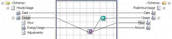
In this example, all the peak hourly energy values from the source XML are mapped over to the destination XML. The Iteration functoid is used to determine the index of each HourlyUsage record, with those having an index value of 3 or higher being flagged as peak hours. Additionally, the output from the Iteration functoid is also used to create the Hour element in the destination XML, defining to which hour the energy reading pertains. The XML snippet in Listing 3-18 represents one possible document instance of the source schema.
Example 3.18. Sample Source Instance for the Iteration Functoid Example
<ns0:HourlyUsage xmlns:ns0="http://IterationFunctoid.HourlyUsage">
  <Date>09/06/2010</Date>
  <Usage>
    <Hour>01</Hour>
    <EnergyUsage>2.4</EnergyUsage>
    <Adjustments>0</Adjustments>
  </Usage>
  <Usage>
    <Hour>02</Hour>
    <EnergyUsage>1.7</EnergyUsage>
    <Adjustments>1</Adjustments>
  </Usage>
  <Usage>
    <Hour>03</Hour>
    <EnergyUsage>3.9</EnergyUsage>
    <Adjustments>0</Adjustments>
  </Usage>
  <Usage>
    <Hour>04</Hour>
    <EnergyUsage>12.4</EnergyUsage>
    <Adjustments>3</Adjustments>
  </Usage>
  <Usage>
    <Hour>05</Hour>
    <EnergyUsage>15</EnergyUsage>
    <Adjustments>0</Adjustments>
  </Usage>
  <Usage>
    <Hour>06</Hour>
    <EnergyUsage>3.2</EnergyUsage>
    <Adjustments>1</Adjustments>
  </Usage>
</ns0:HourlyUsage>
When passed through the map displayed in Figure 3-37, this XML will produce the XML document shown in Listing 3-19, containing all the peak hourly energy usage values with their associated Hour value.
Example 3.19. Sample Destination Instance for the Iteration Functoid Example
<ns0:PeakHourUsage xmlns:ns0="http://IterationFunctoid.PeakHourUsage">
 <Date>09/06/2010</Date>
 <Usage>
  <Hour>4</Hour>
  <Amount>12.4</Amount>
 </Usage>
 <Usage>
  <Hour>5</Hour>
  <Amount>15</Amount>
 </Usage>
 <Usage>
  <Hour>6</Hour>
  <Amount>3.2</Amount>
 </Usage>
</ns0:PeakHourUsage>
The Iteration functoid can be a crucial tool for those business scenarios that require the current index number of a looping structure within a map to be known. In the energy usage example, it allows a generic list of chronological usage values to be mapped to a document containing only those values that occur in the afternoon, along with adding an element describing to which hour that usage pertains. As the map processes the repeating HourlyUsage records in the source XML in a sequential fashion, the index from the Iteration functoid is passed to the logical Greater Than functoid, which compares the index with a hard-coded value of 3. If the index value is 4 or greater, the element is created in the destination XML, and its hour ending value is set.
This example works well for the purposes of our simple scenario, but those who have dealt with hourly values of any kind know that days on which daylight saving time (DST) falls need to be handled carefully. Since the time change associated with DST actually occurs early in the morning, there are 13 morning (before afternoon) hourly values in the fall occurrence of DST, and 11 morning hourly values in the spring occurrence.
The map in Figure 3-37 can easily be enhanced to account for this by adding logic based on the record count of hourly values in the source XML document. You can accomplish this via the following steps:
Click the Toolbox, and click the Advanced Functoids tab. On the map surface, between the source and destination schemas, drag and drop a Record Count functoid. This functoid accepts a repeating source record (or data element) as its one input parameter. The return value is the count of repeating source records contained in a specific instance document.
Connect the left side of the Record Count functoid to the repeating source record (or data element) whose index is the key input for the required decision logic.
Drag and drop a Subtraction functoid from the Mathematical Functoids tab onto the map surface, positioning it to the right of the Record Count functoid. This functoid accepts a minimum of 2 and a maximum of 99 input parameters. The first is a numeric value, from which all other numeric input values (the second input parameter to the last) are subtracted. The return value is a numeric value equaling the first input having all other inputs subtracted from it.
Connect the right side of the Record Count functoid to the left side of the Subtraction functoid.
Specify the second input parameter for the Subtraction functoid as a constant, with a value of 12.
Connect the right side of the Subtraction functoid to the left side of the Greater Than functoid. Ensure that this input to the Greater Than functoid is the second input parameter.
In this modified example, the repeating source record's count has 12 subtracted from it to adjust for the two DST days of the year (this works since we are interested in only the afternoon energy usage values, which are always the final 12 readings for a day). This adjusted value is then passed through the same logical Greater Than functoid as in the previous example, and the DST issue is effectively handled.
The use of the Iteration functoid is common in a number of other scenarios. One such scenario is when dealing with a document formatted with comma-separated values (CSV). Often, the first row in a CSV document contains column header information, as opposed to actual record values. The following flat file snippet shows one possible representation of energy usage values in CSV format:
EnergyUsage,Adjustments
2.4,0
2.5,0
2.8,0
In cases like these, it is likely that you do not want to map the column headers to the destination XML document. You can use an Iteration functoid to skip the first record of a CSV document. The index from the Iteration functoid is passed to a logical Not Equal functoid, which compares the index with a hard-coded value of 1. If the index is anything other than 1 (the record at index 1 contains the column header information), the values are mapped to the destination XML.
Note
You can also strip out column headers by using envelope schemas.
Another common use of the Iteration functoid is to allow the interrogation of records preceding or following the currently processed record. This can be helpful when mapping elements in a repeating record in the source schema that require knowledge of the next or previous record.
Rather than writing the same inline code (C#, XSLT, and so on) and pasting it in multiple shapes, or using a combination of multiple existing functoids, you can develop your own custom functoid.
As an example, we'll describe the process to develop, deploy, and use a custom functoid that replaces the ampersand (&), greater than (>), and less than (<) symbols with their HTML/XML equivalents. The functoid will have one input parameter and one output parameter, representing the string on which to run the replacement. This functoid would be used primarily with XML that may be returned from an external source, such as a .NET assembly, where the XML may not have been validated and contains characters that must be escaped.
Use the following steps to create, deploy, and use a custom functoid. Refer to the sample solution SampleCustomFunctoid.sln included with this book.
Create a new Class Library .NET project. Functoids can be coded in any .NET language. This example is implemented in C#.
Add a reference to the
Microsoft.BizTalk.BaseFunctoids.dllassembly located in the%Program FilesMicrosoft BizTalk Server 2010Developer Toolsdirectory.Create a resource file (
resx) to store the functoid configuration parameters. The name of the file and the parameters should match what is shown in Listing 3-20.Note
Adding a bitmap (or any file) to a resource file may require using a third-party application. You can download such applications freely from the Internet.
Code the functoid. The functoid code should match that shown in Listing 3-20. This is a complete C# class library and will compile into a deployable functoid.
Example 3.20. Custom Functoid Class Library
using System;
using Microsoft.BizTalk.BaseFunctoids;
using System.Reflection;

namespace SampleCustomFunctoid
{
    /// <summary>
    /// See sample solution (SampleCustomFunctoid.sln)
    /// which accompanies this recipe
/// </summary> [Serializable] public class EncodeFunctoid : BaseFunctoid { public EncodeFunctoid() : base() { //Custom functoids should begin with 6000 or higher this.ID = 6667; // resource assembly reference SetupResourceAssembly ("SampleCustomFunctoid.SampleCustomFunctoidResource", Assembly.GetExecutingAssembly()); //Set the properties for this functoid SetName("SAMPLECUSTOMFUNCTOID_NAME"); SetTooltip("SAMPLECUSTOMFUNCTOID_TOOLTIP"); SetDescription("SAMPLECUSTOMFUNCTOID_DESCRIPTION"); SetBitmap("SAMPLECUSTOMFUNCTOID_BITMAP"); // one parameter in, one parameter out this.SetMinParams(1); this.SetMaxParams(1); //Function code below SetExternalFunctionName(GetType().Assembly.FullName, "SampleCustomFunctoid.EncodeFunctoid", "EncodeChars"); //Category in Toolbox where this functoid will appear this.Category = FunctoidCategory.String; //output of functoid can go to all nodes indicated this.OutputConnectionType = ConnectionType.All; // add one of the following lines of code for every input // parameter. All lines would be identical. AddInputConnectionType(ConnectionType.All); } // Actual function which does the replacement of symbols public string EncodeChars(String strInputValue) { strInputValue = strInputValue.Replace("&","&"); strInputValue = strInputValue.Replace("<","<"); strInputValue = strInputValue.Replace(">",">"); return strInputValue; } } }Add a strong name key, and build the project.
Place a copy of the assembly in the following directory:
%Program FilesMicrosoft BizTalk Server 2010Developer ToolsMapper Extensions.To add the functoid to the toolbox, on the window toolbar, click Tools
Note
Functoids can be tested in maps without deploying to the GAC.
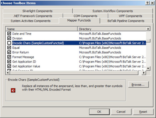
This completes the steps for creating a custom functoid. You can now add the functoid to a BizTalk map and test it. When a map is ready for deployment, the functoid will need to be copied to the Mapper Extensions folder (see step 6) and the GAC on the production server. Figure 3-39 shows the new functoid with custom bitmap in the toolbox in Visual Studio.
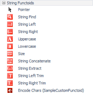
One of the biggest benefits to using custom functoids is that you have full access to the .NET libraries. Inline code within maps gives only limited access to libraries, and coding is often primitive. Custom functoids are created as .NET class libraries, and they have all of the related coding benefits.
The example shown in this recipe is very simple. Custom functoids do not have to be limited to the two functions shown in the code. For example, assume that you need a functoid that does some sort of interaction with a database. You may need to include an Init() function and a deconstructor to terminate a connection, all of which can be included in the class library.
Additionally, you may need multiple input parameters for your functoid. Additional parameters can be added very easily. See Listing 3-21 for an example of a functoid with three input parameters.
Example 3.21. Multiple Input Parameters for a Custom Functoid
SEE CODE FROM Listing 3-20.

            // three parameters in, one parameter out
            this.SetMinParams(3);
            this.SetMaxParams(3);

            ...

            // add one of the following lines of code for every input
// parameter. All lines would be identical.
AddInputConnectionType(ConnectionType.All); // input parameter 1
AddInputConnectionType(ConnectionType.All); // input parameter 2
AddInputConnectionType(ConnectionType.All); // input parameter 3
}
// Actual function which does the replacement of symbols
public string EncodeChars(String strInputValue, strReplace1, strReplace2)
{
strInputValue = strInputValue.Replace("&",strReplace1);
strInputValue = strInputValue.Replace("<",strReplace2);
return strInputValue;
}You are mapping a message in BizTalk Server and need to manipulate date and time fields. Specifically, you must use the current date in order to determine a required date and time in the future, which is added to the outbound message during mapping. Additionally, you must apply the processing time for each document during mapping.
Within a map, use the Date and Time functoids provided with BizTalk Server. To apply the current processing time to the outbound document within the map, take the following steps:
Click the toolbox, and then click the Date and Time Functoids tab. On the map surface, in between the source and destination schemas, drag and drop a Date and Time functoid. Since this functoid simply outputs the current date and time, it requires no input values.
Connect the right side of the Date and Time functoid to the element in the destination schema containing the date and time the message is processed.
To determine a future date based on the current date, take the following steps:
Drag and drop a Date functoid from the Date and Time Functoids tab of the toolbox onto the map surface. This functoid is similar to the Date and Time functoid but returns only the current date, as opposed to the current date and time. It also requires no input values.
Drag and drop an Add Days functoid from the Date and Time Functoids tab onto the map surface, positioning it to the right of the Date functoid. This functoid accepts two input parameters: a date or datetime value, and a numeric value indicating the number of days to add to the date supplied in the first input parameter. The return value is the date with the specified amount of days added.
Connect the right side of the Date functoid to the Add Days functoid.
Specify the second input parameter for the Add Days functoid as a constant with a value of 1.
Connect the right side of the Add Days functoid to the element in the destination schema containing the future date.
An example of a map that uses the Date and Time functoids is shown in Figure 3-40.
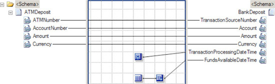
This example captures the current date and time in the TransactionProcessingDateTime element, which is supplied by the Date and Time functoid. The format of the date and time produced by the Date and Time functoid is YYYY-MM-DDThh:mm:ss, which is ISO 8601-compliant. The time values are notated in 24-hour format.
The future date that the deposited funds will be available is captured in the FundsAvailableDateTime element. This value is based off the current date, supplied by the Date functoid, with a single day added to it to provide tomorrow's date, which is supplied by the Add Days functoid. The format of the Date functoid's output is YYYY-MM-DD, while the Add Days functoid accepts dates formatted as YYYY-MM-DD or YYYY-MM-DDThh:mm:ss. The format of the Add Days functoid's output is YYYY-MM-DD. All date formats used by these two functoids are ISO 8601–compliant. The time values are notated in 24-hour format.
The XML in Listing 3-22 represents one possible instance of the source schema.
Example 3.22. Sample Source Instance for the Date/Time Functoid Example
<ns0:ATMDeposit xmlns:ns0="http:// DateTimeFunctoids.ATMDeposit">
  <ATMNumber>00111</ATMNumber>
  <AccountNumber>123456</AccountNumber>
  <Amount>100.00</Amount>
  <Currency>USD</Currency>
</ns0:ATMDeposit>
When passed to the map in Figure 3-40, this XML message will produce the outbound XML document shown in Listing 3-23.
Example 3.23. Sample Output Instance for the Date/Time Functoid Example
<ns0:BankDeposit xmlns:ns0="http://Mapping.BankDeposit">
  <TransactionSourceNumber>00111</TransactionSourceNumber>
  <Account>123456</Account>
  <Amount>100.00</Amount>
  <Currency>USD</Currency>
  <TransactionProcessingDateTime>2010-09-06T16:32:05</TransactionProcessingDateTime>
  <FundsAvailableDateTime>2010-09-07</FundsAvailableDateTime>
</ns0:BankDeposit>
The Date and Time functoids provide a baseline set of functionality when needing to interrogate and manipulate date and time values. In the bank account example, the Date and Time functoid provides the current date and time, allowing a timestamp to be applied to the outbound document, indicating the time that the message was processed. Often, messages include an element or elements detailing the time that the message pertains to, or the time at which a message was created. The Date and Time functoid is useful when the actual processing time (in this example, the time a deposit is processed within a bank's integration system) is required, which will likely be different from any time value embedded in the source document. The difference between date and time values within a source instance message and the actual processing time of the message can be particularly important when dealing with batched or time-delayed processes.
This example also shows how you can use the Date and Add Days functoids in conjunction to calculate a future date based on the day a message is processed. The current date is provided by the Date functoid, which is used by the Add Days functoid to come up with a date that is a specified number of days in the future. In the bank account scenario, this functionality is used to determine the day on which deposited funds are available. Business rules like this can be common among financial institutions, as validation procedures are often required when dealing with monetary transactions.
Note
You can also use a negative numeric value with the Add Days functoid, resulting in a date that is the specified number of days in the past. For this example, the Date and Time functoid (substituting for the Date functoid) could have been used as the first input parameter for the Add Days function, and the map would be functionally equivalent. This is due to the fact that the Add Days functoid can accept either date or datetime values, and in either case, produces only a value indicating a date (excluding a time element).
This bank account example can be extended to illustrate how the Time functoid can be used to add a time component to the data capturing the date at which deposited funds are available. Currently, the example simply calculates a date for this value, but it is likely that a financial institution would additionally need to know the time at which deposited funds should be made available for use. Since the Add Days functoid produces only date values (without a time component), you must use a Time functoid, in addition to a String Concatenate functoid. To implement this enhancement, take the following steps:
On the mapping grid, in between the source and destination schemas, drag and drop a Time functoid. Since this functoid simply outputs the current time, it requires no input values.
Drag and drop a String Concatenate functoid onto the mapping grid. This functoid allows multiple string values to be concatenated, or added, together.
Delete the current connection between the Add Days functoid and the element in the destination schema containing the future date that the deposited funds will be available in the bank account.
Connect the right side of the Add Days functoid to the String Concatenate functoid.
Specify the second input parameter for the String Concatenate functoid as a constant, with a value of
T. This value is required in between the date and time portions of a datetime value for ISO 8601–compliant values.Connect the right side of the Time functoid to the String Concatenate functoid. The String Concatenate functoid should look like Figure 3-41.
Connect the right side of the String Concatenate functoid to the element in the destination schema containing the future date that the deposited funds will be available in the bank account.
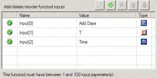
Figure 3-42 shows an example of a map implementing these changes.
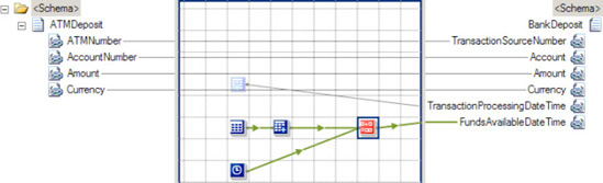
Based on the same source XML used in the preceding example, the map in Figure 3-42 will produce the XML document shown in Listing 3-24, with a time component included in the FundsAvailableDateTime element.
Example 3.24. Sample Output Instance for the Time Functoid Example
<ns0:BankDeposit xmlns:ns0="http://Mapping.BankDeposit">
  <TransactionSourceNumber>00111</TransactionSourceNumber>
  <Account>123456</Account>
  <Amount>100.00</Amount>
  <Currency>USD</Currency>
  <TransactionProcessingDateTime>2010-09-06T16:32:04</TransactionProcessingDateTime>
  <FundsAvailableDateTime>2010-09-07T16:32:05</FundsAvailableDateTime>
</ns0:BankDeposit>
One common challenge when dealing with datetime values is standardizing on a common format. This issue can be seen with dates adhering to the MM-DD-YYYY (common in the United States) or DD-MM-YYYY (common in Europe and other areas) format. Unfortunately, BizTalk Server does not have any Date and Time functoids that do complex datetime formatting. There are a number of ways to handle this issue. The simplest way is to use string functoids provided with BizTalk Server to manipulate and standardize the order of year, month, and day values. Specifically, you can use String Extract functoids to pull out values within a date (in this scenario, you would pull out the DD, MM, and YYYY values in three separate String Extract functoids), and then a String Concatenate functoid to combine the individual values in the correct format (in this scenario, you would append the three values in an order of YYYY-MM-DD).
There are also more robust ways of implementing complex date/time formatting. One option is to use the Scripting functoid, which provides access to the libraries of C#, VB .NET, and JScript .NET (either via inline code embedded in the map, or by referencing external assemblies written in one of the .NET-compliant languages). Additionally, you could use a custom functoid (which would leverage the datetime functionality of a .NET language).
You need to map values from the source to the destination message depending on whether a logical condition evaluates to true or false.
Define the logical condition that the mapping actions should be based on by dragging logical functoids from the toolbox onto the map surface. Any functoid or combination of functoids that returns a Boolean value can establish the logical condition, but these functoids can return only true or false.
In this example, the logical condition will check whether the amount of a sale is greater that 1,000, as shown in Figure 3-43.
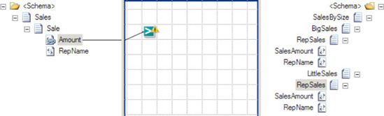
Only large sales should appear under the <BigSales> element in the destination message, so the logical condition will check if the Amount in the source message is greater than 1,000. The following steps define the logical operation that determines mapping actions, as shown in Figure 3-44.
Drag a Greater Than functoid from the Logical Functoids tab of the toolbox onto the map surface.
Select the
Amountfield of the input message. Drag the cursor over the Greater Than functoid while pressing the mouse button to establish the first comparison value.Right-click the functoid on the map surface, and select Properties.
In the Properties window, click the
Input Parametersfield, and select the ellipsis that appears.Define the constant value in the Configure Functoid Inputs dialog box.
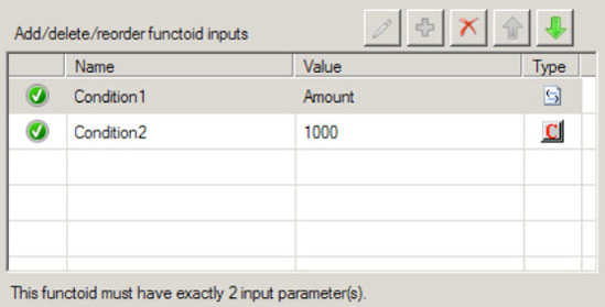
Next, define the mapping actions that depend on the evaluation of the logical condition. In this example, the contents of the <Sales> elements should map to different parts of the destination message, so the map must use the Boolean outcome of the logical comparison as input to a Value Mapping functoid.
Drag a Value Mapping functoid from the Advanced Functoids tab of the toolbox to the right and below the Greater Than functoid.
Create a link from the Greater Than functoid to the Value Mapping functoid.
Create a link from the
Amountfield of the input message to the Value Mapping functoid to determine the value mapped when the logical condition istrue.Create a link from the Value Mapping functoid to the
SaleAmountfield appearing under theBigSalesrecord to define where the large value will occur in the destination message.
The Value Mapping functoid defines the action the map should take when the logical condition evaluates to true. Both the amount of the big sale and the name of the sales representative must appear in the destination message in this example, so the map must use two Value Mapping functoids, as shown in Figure 3-45.
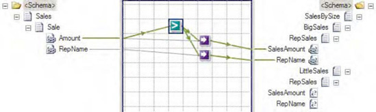
BizTalk must also know that it should create only the <RepSales> element in the destination message when the amount is greater that 1,000. Establishing a link from the logical operator to the RepSales element will ensure that BizTalk creates this parent to the actual values mapped.
When the logical condition evaluates to false, BizTalk should map the sale to the <SmallSales> part of the destination message. The map can check this directly by placing a Not Equal functoid on the mapping surface and comparing to the result of the logical comparison established earlier with a constant value equal to true, as shown in Figure 3-46.
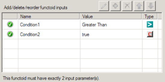
Finally, define the mapping actions that BizTalk should take when the logical comparison is not true. In this example, the Value Mapping functoids simply need to map under the <SmallSales> element in the destination message.
Drag a Value Mapping functoid onto the map surface.
Create a link from the Not Equal functoid that represents the else case to the Value Mapping functoid.
Create a link from the
Amountfield of the source message to the Value Mapping functoid.Create a link from the Value Mapping functoid to the
SaleAmountfield appearing under theSmallSalesrecord to define where the small value will occur in the destination message, as shown in Figure 3-47.
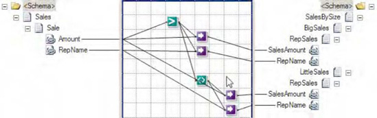
Working with the BizTalk Mapper can be an unfamiliar process, even to experienced programmers. Business rules defined in source code can be procedural and explicit, but the graphical depiction of a BizTalk map can abstract the runtime behavior.
The link to the logical condition defines the information on which the map will perform the logical operation. BizTalk will evaluate the logical condition for each occurrence of the information in the source message, and remember the context of the logical condition when performing the output actions dependent on it. This means that the Value Mapping functoid will automatically know the right Amount and RepName values to map when the map executes.
The order of the Value Mapping functoid inputs is critical. The first input parameter must be either true or false. The second input parameter specifies the value that the functoid will return when the first parameter is true. While the order is established based on the order in which the inputs are connected to the Value Mapping functoid, sometimes the order can get mixed up when modifying the functoid links. There is no indication of the input parameter order on the mapping surface, but fortunately, it is easy to check. Open the Configure Functoid Inputs window, and the Boolean value should appear first in the list. Modify the order here by selecting one of the input parameters and clicking the up and down arrows.
Note
In many cases, If-Then-Else logic using functoids like this can becoming complex and frustrating to implement (and maintain!). The best approach frequently is to use an Advanced Scripting functoid with either XSLT or C# to implement the logic.
This example establishes a logical condition and defines mutually exclusive mapping actions that are directly determined from the evaluation of the logical conditions. Alternatively, a map can define separate logical conditions independently. With this alternative approach, the developer must carefully define the logical conditions to ensure that every input message will map to some outcome, and never both. This becomes an increasingly important consideration as the logical comparison becomes more and more complex.
When there are more than two mutually exclusive outcomes, the Not Equal functoid in this example can be combined with additional logical comparisons by linking its result to the Logical AND functoid. The result of the Logical AND functoid also evaluates to true or false, and the developer can define actions to take based on this result, as with any other logical operator.
You need to access logic contained within an external assembly while transforming a message via a BizTalk Server map. The logic contained within the assembly cannot and should not be embedded within the map.
Create a map that uses the BizTalk Server Scripting functoid's ability to call external assemblies. The following steps outline the procedure:
Click the toolbox, and click the Advanced Functoids tab. On the map surface, between the source and destination schemas, drag and drop a Scripting functoid. This functoid's input and output values are dependent on the logic contained within the Scripting functoid.
Connect the left side of the Scripting functoid to the appropriate source data elements or records. In this solution, no source data elements are used.
Configure the Scripting functoid.
While the Scripting functoid is highlighted on the mapping grid, right-click the functoid, and select Configure Functoid Inputs.
In the Configure Scripting Functoid dialog box, on the Script Functoid Configuration tab, select External Assembly for Script Type and the appropriate assembly, class, and method for Script Assembly, Script Class, and Script Method, as shown in Figure 3-48. Then click OK.
To pass in a parameter, click the ellipsis to the right of Input Parameters in the Properties window.
In the Configure Functoid Inputs dialog box, on the Functoid Inputs tab, create or order the appropriate input parameters for the method specified in step 2, as shown in Figure 3-49, and then click OK.
Connect the right side of the Scripting functoid to the appropriate destination data element or additional functoid (if further logic needs to be applied to the data).
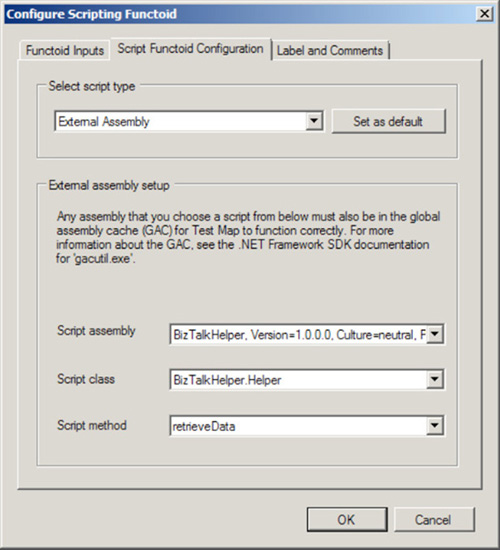
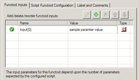
In this example, the functoid in the map determine whether there is enough time before the event for the tickets to be mailed to the purchaser. The XML snippet shown in Listing 3-25 represents one possible instance of the source schema.
Example 3.25. Sample Source Instance for the Scripting Functoid Example
<ns0:TicketRequest xmlns:ns0="http://Mapping.TicketRequest">
  <EventName>Chelsea vs. Arsenal</EventName>
  <EventDate>08/06/2010</EventDate>
  <Venue>Stamford Bridge</Venue>
  <NumberOfTickets>2</NumberOfTickets>
  <PurchasedBy>George Murphy</PurchasedBy>
  <MailTicketFlag>True</MailTicketFlag>
</ns0:TicketRequest>
Based on this source XML, the map will produce the XML document (assuming that the current date is prior to August 4, 2010) shown in Listing 3-26, with the MailedTicketFlag appropriately set.
Example 3.26. Sample Output Instance for the Scripting Functoid Example
<ns0:TicketOrder xmlns:ns0="http://Mapping.TicketOrder">
  <Title>Chelsea vs. Arsenal</Title>
  <Date>08/06/2010</Date>
  <Venue>Stamford Bridge</Venue>
  <NumOfTickets>2</NumOfTickets>
  <TicketHolder>George Murphy</TicketHolder>
  <MailedTicketFlag>True</MailedTicketFlag>
</ns0:TicketOrder>
This example demonstrates one of the many reasons why external assemblies may need to be called from a BizTalk Server map. Here, the external assembly provides access to a configuration value. This value is held in a configuration file (but alternatively could be held in a database or other data store), which is updated over time by system administrators and business analysts. For the purposes of this example, the following configuration value was used.
<add key="MinimumDaysAdvanceForMailedTickets" value="-2" />
The value of −2, which represents the minimum number of days required to mail tickets to a purchaser, is added to the EventDate element (by the Add Days functoid), resulting in a date value two days prior to the event (08/04/2006 in this example). The current date (supplied by the Date functoid) is then compared to the calculated date value (by the Less Than logical functoid) to determine if there is enough time to mail the purchased tickets. Finally, if there is ample time to mail the tickets, and the source document indicates the purchaser requested tickets to be mailed, the MailedTicketFlag element in the destination message is set to true.
The benefit of having the MinimumDaysAdvanceForMailedTickets value stored in a file external to BizTalk, as opposed to being hard-coded within the actual map, is that a change to the value does not require a redeployment of BizTalk Server artifacts for the modification to be applied. Additionally, by encapsulating the custom logic in an external assembly, any changes to that logic will require only that the external assembly is rebuilt and redeployed to the GAC. No changes to the BizTalk Server environment (aside from a BizTalk service restart to immediately apply the changes in the redeployed custom assembly) are required. Implementing this logic in an external assembly has the additional benefits of allowing reuse of the logic, minimizing code maintenance, and providing access to the debugging utilities within Visual Studio.
Note
You can step into the external assembly in debug mode by running the external assembly solution in Visual Studio in debug mode, attaching to the process of the Visual Studio solution containing the BizTalk Server map, and testing the map.
In addition to using a generic external assembly, a custom functoid could also have been used to implement the configuration value retrieval logic. It is important to consider the differences between the two options prior to selecting your design. The main benefit of using a custom functoid is that the assembly is hosted within the BizTalk Server environment. The actual assembly file is located within the BizTalk Server program file directory, and the functoid can be added to the Functoid Toolbox within the development environment. Using generic external assemblies is sometimes a requirement, however, such as when the existing logic contained within them needs to be accessed directly (without modification to the source code or assembly location). This may be the case when using third-party or proprietary assemblies, where you do not have access to the source code.
Other common examples of logic contained in external assemblies are complex database-retrieval mechanisms, calculations above and beyond what is possible with the out-of-the-box mathematical functoids, and complex date and string formatting.
Warning
Care should be taken with regard to data types for values passed into and out of external assemblies. For example, if a source document element having a data type of xs:int is used as an input parameter for a method contained in an external assembly, it will be passed as an integer. Likewise, if the output from an external assembly is used to populate a destination document element having a data type of xs:int, it should be returned as an integer.
You are mapping a message in BizTalk Server and must implement custom logic via an inline C# code snippet. The custom logic should be embedded within the map.
Create a map that uses the BizTalk Server Scripting functoid's ability to call inline C#. The following steps outline the procedure:
Click the toolbox, and click the Advanced Functoids tab. On the map surface, between the source and destination schemas, drag and drop a Scripting functoid. This functoid's input and output values are dependent on the logic contained within the Scripting functoid.
Connect the left side of the Scripting functoid to the appropriate source data elements or records. This specifies the order and location of the Scripting functoid's input parameters.
Configure the Scripting functoid.
While the Scripting functoid is highlighted on the mapping grid, click the ellipsis to the right of the
FunctoidScriptitem in the Properties window.In the Configure Scripting Functoid dialog box, on the Script Functoid Configuration tab, select Inline C# for Script Type and enter your custom C# logic in the Inline Script Buffer text box, as shown in Figure 3-50 (the code for this is shown in Listing 3-27. Then click OK.
Drag the appropriate source field and drop it on the left-hand side of the Scripting functoid (as the input parameter).
In the Configure Functoid Inputs dialog box, create or order the appropriate input parameters for the method specified in step 2, and then click OK.
Connect the right side of the Scripting functoid to the appropriate destination data element or additional functoid (if further logic needs to be applied to the data).
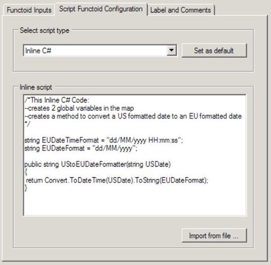
An example of a map that uses the BizTalk Server Scripting functoid's ability to call inline C# is shown in Figure 3-51.
In this example, auction bids from the United States are transformed into European Union (EU) bids. The Scripting functoids used in the map format the date and datetime values common in the United States to those that are common in the EU. The XML snippet in Listing 3-28 represents one possible instance of the source schema.
Example 3.28. Sample Source Instance for the Inline C# Example
<ns0:AuctionBidUS xmlns:ns0="http://Mapping.AuctionBidUS">
  <BidID>12345</BidID>
  <LotID>123-456</LotID>
  <BidDate>09/25/2010</BidDate>
  <LotCloseDateTime>09/18/2010 23:59:59</LotCloseDateTime>
</ns0:AuctionBidUS>
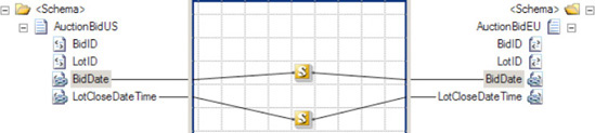
Based on this XML snippet, the map displayed will produce the XML document shown in Listing 3-29. Notice that the format of the BidDate and LotClosedDateTime values have been changed from MM/DD/YYYY and MM/DD/YYYY hh:mm:ss format to DD/MM/YYYY and DD/MM/YYYY hh:mm:ss format, respectively.
Example 3.29. Sample Output Instance for the Inline C# Example
<ns0:AuctionBidEU xmlns:ns0="http://Mapping.AuctionBidEU">
  <BidID>12345</BidID>
  <LotID>123-456</LotID>
  <BidDate>25/09/2010</BidDate>
  <LotCloseDateTime>18/09/2010 23:59:59</LotCloseDateTime>
</ns0:AuctionBidEU>
Date formatting like this is one of countless examples where custom logic could be needed within a BizTalk Server map. In the auction bid example, date and datetime values were formatted with inline C# to account for regional differences. Additionally, in the first Scripting functoid, two variables were defined that specify the date and datetime format for the EU. This illustrates another helpful use of Scripting functoids: the ability to create global variables that can be used by any other functoid within the map. In the example, the UStoEUDateFormatter method in the second Scripting functoid referenced the EUDateTimeFormat variable that was defined in the first Scripting functoid.
Note
All methods defined in inline Scripting functoids should have unique names. This is important to avoid naming conflicts, as all inline script is embedded within the map inside CDATA tags.
You can format dates in a number of different ways within a BizTalk Server map. In our example, we used inline C#, but we could have used either of the other available script languages (VB .NET or JScript .NET), an external assembly, or a custom functoid.
Note
You can reuse methods within other Scripting functoids by calling them just like you would as if they were being called in standard .NET. There is no need to copy and paste the methods with the exact same code and a different name. You can simply declare them as public and then call them from other Scripting functoids.
Inline scripting is a good option when a simple implementation of custom logic is needed, and the logic is unlikely to be leveraged outside the map. It is important to recognize a key limitation of inline scripting: debugging utilities. Because the inline script is embedded into the map's XSLT, stepping into the code at runtime is not possible. One possible way to allow easier debugging of an inline script is to first create and test it in a separate executable or harness. This will allow you to use the robust debugging utilities of Visual Studio. Once the code has been fully tested, it can be placed into a Scripting functoid.
The fact that the inline script is saved in the XSLT of the map has another important consequence: only those libraries available to XSLT style sheet scripts may be leveraged. The following are available namespaces:
System: The system classSystem.Collection: The collection classesSystem.Text: The text classesSystem.Text.RegularExpressions: The regular expression classesSystem.Xml: The XML classesSystem.Xml.Xsl: The XSLT classesSystem.Xml.Xpath: The XPath classesMicrosoft.VisualBasic: The Visual Basic script classes
You need to include information from variables in an orchestration in the destination message of a BizTalk mapping.
Begin by creating a new message schema with fields for capturing the information from the orchestration, as shown in Figure 3-52. The information from the orchestration variables must be set in a separate message from the input message, referred to here as a context message. In this recipe, the mapping will transform a customer purchase message for the customer support department, and the orchestration will define the support information with the business process. BizTalk will use the new message schema to capture the support information.
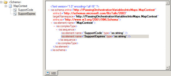
Follow these steps to set up the orchestration.
To access the fields of this message easily from within the orchestration, define them as distinguished fields. Right-click the context message schema tree, and select Promote
Define the following orchestration properties on the Orchestration View tab (see Figure 3-54):
Messages
msgInputMessage(map to the Input message schema)msgOutputMessage(map to the Output message schema)msgContext(map to the MapContext schema)
Orchestration variables
strSupportCode(a string)strSupportCodeExpires(also a string)xmlXmlDoc(of typeSystem.Xml.XmlDocument)
In the Orchestration Designer, drag a Message Assignment shape from the toolbox onto the orchestration surface. In the properties of the Construct Message shape that appears around the Message Assignment shape, specify
msgContextas the only message constructed, as shown Figure 3-55.Double-click the Message Assignment shape to open the BizTalk Expression Editor window. Load an XML string conforming to the schema of the context message into the
xmlXmlDocvariable. Then create themsgContextmessage by assigning the loadedXmlDocumentvariable to it. This example uses the code shown in Listing 3-30 and in Figure 3-56.
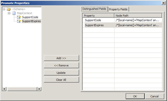
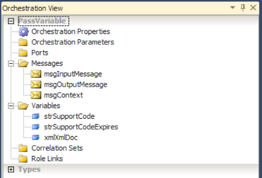
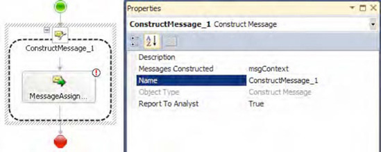
Note
Obtain a sample XML string by right-clicking the schema in the Solution Explorer and selecting Generate Instance. Copy and paste this into the LoadXml method.
Example 3.30. Build the Context Message
xmlXmlDoc.LoadXml("<ns0:MapContext xmlns:ns0=
'http://PassingOrchestrationVariablesIntoMaps.MapContext'>
<SupportCode>SupportCode_0</SupportCode> <SupportExpires>SupportExpires_0</SupportExpires>
</ns0:MapContext>");

msgContext = xmlXmlDoc;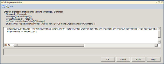
Once instantiated, the values in MapContextMsg can be set anywhere in the orchestration. For simplicity in this example, they are created and set in the same Message Assignment shape, and the expiration is the same day that the context message is created, as shown in Listing 2-31 and Figure 3-57.
Example 3.31. Set the Values in the Orchestration
msgContext.SupportCode = "R-2";
msgContext.SupportExpires = System.DateTime.Now.ToString("yyyy-MM-dd");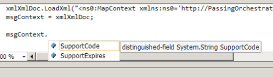
Once the context message contains the required orchestration information, the BizTalk orchestration must create the mapping. The orchestration must create mappings that have more than one source or destination message.
Drag a Transform shape onto the Orchestration Designer surface.
Double-click the new Transform shape to open the Transform Configuration dialog box.
Specify the source messages to be the
msgInputMessageandMapContextMsgmessages, as shown in Figure 3-58.Specify
msgOutputMessagefor the destination message, and then click OK.
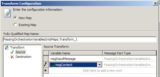
BizTalk will generate a new transformation with two input messages and one output message. One of the input messages will be the MapContextMsg message containing the values from the orchestration. The developer can choose to either drive mapping logic from these values or map them directly to the destination message as in this example, as shown in Figure 3-59.
Warning
BizTalk may not be able to recognize the second schema if the project name begins with a number.
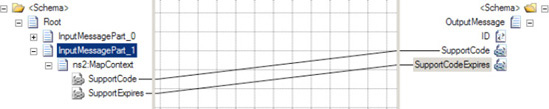
BizTalk developers often think about translation among message types when defining integration processes in an orchestration. They can place a Transform shape directly within an orchestration to transform a message into different formats, so it seems that the transformation and orchestration are integral to each other. However, the BizTalk mapper cannot directly access the contextual information of the business process and the logic existing in the orchestration.
The BizTalk Mapper can natively access many resources outside the map with the default functoids. For example, the Database Lookup functoid can access records in a database, and the Scripting functoid can invoke an external assembly. However, the most direct way to access information about the context of the business process is by creating a message specifically for capturing the state of the business process. Add the information required in the mapping to this additional message, and then add the context message as an additional input message to the map.
The possible reasons for passing information from an orchestration into a mapping with a second message are as varied as the capabilities of BizTalk orchestrations. However, in all cases, the mapping destination message must contain information that cannot or should not be added to the schema of the input message. Here are some examples:
A standards body such as RosettaNet sets the source message schema, and it should not change.
The mapping must access message context properties. A map cannot access these values. For example, if the SMTP adapter is used, an orchestration can access the sender with the
SMTP.Fromproperty but not directly from the BizTalk Mapper. The destination message may need this information.The mapping must include information about the business process that is not known until runtime and is required in the orchestration. Rather than duplicating the logical definitions, define each definition once within the orchestration and pass the information to the mapping.
BizTalk must be capable of modifying the mapped values without redeploying the BizTalk artifacts. For example, the BizTalk rules engine can be easily invoked from within an orchestration and facilitates additional capabilities like rule versioning and seamless deployment.
You need to map an incoming document with a node containing a document that matches exactly the destination schema. All of the nodes in the source document need to be mapped in their entirety to the destination document. Both the source and the destination schemas have target namespaces, and the namespaces must be preserved.
By using inline XSLT within a Scripting functoid, you can create the target document with the appropriate nodes and the correct namespace. Listing 3-32 shows a sample input document.
Example 3.32. Sample Input Document for the Inline XSLT Example
<ns0:SampleSource xmlns:ns0="http://Sample.Source">
  <ID>ID_0</ID>
  <Payload>
    <SampleDestination>
      <Name>Name_0</Name>
      <Address>Address_0</Address>
      <Company>Company_0</Company>
    </SampleDestination>
  </Payload>
</ns0:SampleSource>
The inline XSLT is written to parse the incoming document as a whole; there is no need to have an input to the Scripting functoid. The output of the Scripting functoid occurs under the node that the output is tied to—in this case, the XSLT output will be directly below the SampleDestination element. When XML documents contain namespaces, use the local-name() qualifier to reference a specific node by name. Because of the requirement that the namespaces be preserved, it is necessary to copy each of the nodes in the source document's Payload node (which consists of an Any element that can contain any XML structure) separately to the destination document.
Figure 3-60 shows the configuration for the Scripting functoid with the inline XSLT for the <Name> element. Additional nodes (such as Address and Company) can be added using the same code pattern. See Listing 3-33 for the XSLT code.
Example 3.33. XSLT Code
<xsl:if test="//*[local-name()='SampleDestination'])/*[local-name()='Name']">
 <xsl:element name="Name">
 <xsl:value-of select="//*[local-name()='SampleDestination']/*[local-name()='Name']"/>
</xsl:element>
</xsl:if>
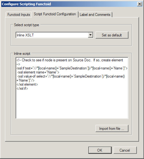
This XSLT script will produce the desired XML document on output, as shown in Listing 3-34.
The two expected solutions to this, the Mass Copy functoid or the <xsl:copy-of> function, both end up requiring additional logic and code outside the map due to the presence of the namespaces. These can be solved in orchestration mapping but not in maps outside orchestrations. An additional approach would be to reference an external XSLT file where more complex functions are available.
The Mass Copy functoid, designed specifically to copy entire documents to a destination node, is a graphic representation of the XSLT <xsl:copy-of> function. Both of these copy the entire source document to the destination document. The problem is that the source document namespace will be copied to the target document, regardless of the node level being copied. There is no simple way in XSLT to remove the source document namespace. For instance, if in the given solution for this recipe, the inline XSLT was changed to simply read:
<xsl:copy-of select="//*[local-name()='Payload']"/>
The following document would be created on output of the map (note that the root node contains the namespace of the source schema):
<Payload xmlns:ns0="Sample.Source">
  <SampleDestination>
    <Name>Name_0</Name>
    <Address>Address_0</Address>
    <Company>Company_0</Company>
  </SampleDestination>
</Payload>
If a Mass Copy functoid were used on the Payload node, the following document would be produced (note that the root node repeats itself and that it contains the namespace of the source schema):
<ns0:SampleDestination xmlns:ns0="http://Sample.Dest">
  <SampleDestination xmlns:ns0="http://Sample.Source">
    <Name>Name_0</Name>
    <Address>Address_0</Address>
    <Company>Company_0</Company>
  </SampleDestination>
</ns0:SampleDestination>
The output document for both of these approaches is not the desired outcome. However, if the mapping is being done in an orchestration, the output document will be in a message that can now be accessed and corrected in a Message Assignment shape, using the code in Listing 3-35.
Example 3.35. Message Assignment
// xmlDoc is a variable of type System.Xml.XmlDocument()
// msgSampleDestination contains the output of the map

// xpath will access the contents of the SampleDestination node
xmlDoc = xpath(msgSampleDestination, "/*/*");

// populate the message
msgSampleDestination = xmlDoc;
Another option would be to move the entire solution to an external XSLT document, where more complex functions such as templates are available, and reference it in the map directly rather than using the mapping functions. This can be done by selecting properties on the map being developed and indicating the path to the XSLT file in the Custom XSLT Path property.
Note
One of the greatest skills in BizTalk mapping is becoming proficient with XSLT. Functoids are great, but knowing how to code is even better! Do yourself a favor and learn how to apply Inline XSLT scripting to your maps. You will be astounded at how much easier it is to write a map that is intelligent and maintainable.
In summary, a number of approaches can be taken to map an incoming document with a node containing a document that matches exactly the destination schema. The cleanest and most viable approach is described in this recipe's solution. Quicker and more convoluted solutions involve using the Mass Copy functoid and <xsl:copy-of> function. An additional approach is to move the mapping completely out of the map into a separate XSLT document. The appropriate solution must be decided by the developer.
You want to use the inline XSLT call template functionality within the Scripting functoid and understand the difference between inline XSLT and an inline XSLT call template.
Use the following steps to add an Inline XSLT Call Template functoid call to a map. The steps assume the schemas shown in the map in Figure 3-61 are being used.
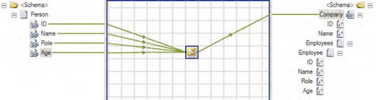
Click the toolbox, and then click the Advanced Functoids tab. Drop a Scripting functoid onto the map surface.
While the Scripting functoid is highlighted on the mapping grid, click the ellipsis to the right of the
FunctoidScriptitem in the Properties window. In the Configure Scripting Functoid dialog box, on the Script Functoid Configuration tab, select Inline XSLT Call Template for Script Type, place the code shown in Listing 3-36 into the Inline Script Buffer text box, and then click OK.Example 3.36. Template Code
<xsl:template name="CreateCompanySchema">
<xsl:param name="ID" />
<xsl:param name="Name" />
<xsl:param name="Role" />
<xsl:param name="Age" />
<xsl:element name="Company">
 <xsl:element name="ID">Default Company ID</xsl:element>
 <xsl:element name="Name">Default Company Name</xsl:element>
 <xsl:element name="Employees">
  <xsl:element name="Employee">
   <xsl:element name="ID"><xsl:value-of select="$ID" /></xsl:element>
   <xsl:element name="Name"><xsl:value-of select="$Name" /></xsl:element>
   <xsl:element name="Role"><xsl:value-of select="$Role" /></xsl:element>
   <xsl:element name="Age"><xsl:value-of select="$Age" /></xsl:element>
  </xsl:element>
</xsl:element>
</xsl:element>
</xsl:template>
Create four input parameters by dropping each of the four nodes (
ID, Name, Role, andAge) in the source document onto the Scripting functoid.Drop the output of the functoid onto the root node (
Company) of the destination schema.Test the map. Assuming that the input document that is shown in Listing 3-37 is used as input, the document shown in Listing 3-38 will be output.
Calling an XSLT template is very similar to using inline XSLT. The main difference is the way in which values within the source document are passed and accessed. With inline XSLT, node values in the source document are accessed through XSL methods, whereas with called XSLT templates, the values are passed in as parameters.
In the case where code may need to be reused for multiple nodes, it may be more advantageous to create a template that can be reused without modifying the code. Templates will also allow for more traditional programming techniques, such as setting and updating variables dynamically within the template (for example, the ability to update a variable to store the number of loops that have occurred within a for-each loop).
Listing 3-39 demonstrates the use of inline XSLT rather than a called XSLT template. The output of Listing 3-39 will produce the same output as that of the XSLT template code shown earlier in Listing 3-36.
Example 3.39. Inline XSLT for Comparison
<xsl:element name="Company">
 <xsl:element name="ID">Default Company ID</xsl:element>
 <xsl:element name="Name">Default Company Name</xsl:element>
 <xsl:element name="Employees">
  <xsl:element name="Employee">
   <xsl:element name="ID">
    <xsl:value-of select="//*[local-name()='ID']" />
   </xsl:element>
   <xsl:element name="Name">
    <xsl:value-of select="//*[local-name()='Name']" />
   </xsl:element>
   <xsl:element name="Role">
    <xsl:value-of select="//*[local-name()='Role']" />
   </xsl:element>
   <xsl:element name="Age">
    <xsl:value-of select="//*[local-name()='Age']" /></xsl:element>
   </xsl:element>
  </xsl:element>
 </xsl:element>
</xsl:element>You need to define mapping from an input message with a flat structure to an output message grouping elements by the values of fields in the input message.
The input message must have records containing a field on which the grouping should be performed, as well as the information that needs to be grouped together. The output message needs to define records for each group and a field containing the aggregated information. The input message may have a structure similar to the XML in Listing 3-40.
Example 3.40. Sample Source Message for the XSLT Group-By Example
<ns0:Sales xmlns:ns0="http://tempURI.org">
  <Sale>
    <Amount>100.01</Amount>
    <RepName>Megan</RepName>
  </Sale>
  <Sale>
    <Amount>200.01</Amount>
    <RepName>Megan</RepName>
  </Sale>
  <Sale>
    <Amount>10.10</Amount>
    <RepName>Leah</RepName>
  </Sale>
  <Sale>
    <Amount>2000</Amount>
    <RepName>Misti</RepName>
  </Sale>
  <Sale>
    <Amount>50.10</Amount>
    <RepName>Leah</RepName>
  </Sale>
</ns0:Sales>
To create the mapping, follow these steps:
Click the toolbox, and click the Advanced Functoids tab. Place a Scripting functoid on the map surface and connect it to the record that will contain each group in the destination message.
While the Scripting functoid is highlighted on the map surface, click the ellipsis to the right of the
FunctoidScriptitem in the Properties window. In the Configure Scripting Functoid dialog box, on the Script Functoid Configuration tab, select Inline XSLT for Script Type.Create an
xsl:for-eachelement in the inline XSLT script, and define the groups to create in the output message by selecting the unique values of the grouping field. This statement will loop through each unique value appearing in the input message.Inside the
xsl:for-eachelement, create the record that should contain the group and the field containing the value that must be aggregated for the group. Thecurrent()function obtains the current iteration value of thexsl:for-eachelement's select statement. Listing 3-41 shows the inline XSLT.
Example 3.41. Inline XSLT Group-By Script
<xsl:for-each select="//Sale[not(RepName=preceding-sibling::Sale/RepName)]/RepName">
  <RepSales>
    <RepTotalAmount>
        <xsl:value-of select="sum(//Sale[RepName=current()]/Amount)"/>
     </RepTotalAmount>
    <RepName>
        <xsl:value-of select="current()"/>
    </RepName>
  </RepSales>
</xsl:for-each>
This XSLT script will produce the XML message shown in Listing 3-42, containing one RepSales element for each sales representative with the total sales and name of the representative.
Example 3.42. Sample Destination Message for the XSLT Group-By Example
<ns0:SalesByRep xmlns:ns0="http://tempURI.org">
  <RepSales>
    <RepTotalAmount>300.02</RepTotalAmount>
    <RepName>Megan</RepName>
  </RepSales>
  <RepSales>
    <RepTotalAmount>60.2</RepTotalAmount>
    <RepName>Leah</RepName>
  </RepSales>
  <RepSales>
    <RepTotalAmount>2000</RepTotalAmount>
    <RepName>Misti</RepName>
  </RepSales>
</ns0:SalesByRep>The key feature of this inline XSLT example is the select statement appearing in the xsl:for-each element. This statement will create a list of values to create a group for, containing the distinct values of RepName in our example. Each RepName is located at //Sale/RepName in the input message. However, the select statement should obtain only the first occurrence of each distinct group value. This inline example achieves this by adding the filter [not(RepName=preceding-sibling::Sale/RepName)] to the select statement. The xsl:for-each element will loop through the first occurrence of each unique grouping value, and the value can be obtained within the xsl:for-each element with the current() function.
When the filter expression evaluates a Sale element, the condition RepName=preceding-sibling::Sale/RepName is true whenever there is an element appearing before it with the same RepName value. Placing the condition inside the not() function makes it true only when there are no preceding elements with the same RepName value, so it is only true for the first occurrence of each distinct RepName value.
The inline XSLT script in Listing 3-41 calculates the total sales of each representative and creates one record in the output message containing the total sales and the sales representative's name.
In addition to grouping fields in the output message, the map may need to perform aggregations for the groups of input message values. Perhaps BizTalk cannot determine the specific groupings that the map needs to perform until runtime, or static links may not be practical because of a large number of possible groups.
When inline XSLT performs the grouping, BizTalk applies the filter expression to the //Sale statement, which means BizTalk applies the filter expression to every Sale element in the input message. For each input message, the expression checks the value of every preceding-sibling and returns true when none of the preceding-sibling elements has the same RepName value. This algorithm is not efficient for large messages.
There is a generally more efficient alternative XSLT approach to the group by problem. This alternative approach is the Muenchian method. The Muenchian method is generally more efficient than the inline solution presented here, but the default BizTalk functoids cannot implement it. The Muenchian method declares an xsl:key element at the top level of the XSLT style sheet. The map directly obtains a node set for each distinct RepName with an xsl:key, eliminating the computational cost of checking every preceding sibling incurred with inline XSLT. However, since the top level of the xsl:stylesheet element must declare the xsl:key element, inline XSLT cannot implement it. Only a separate style sheet file can implement the Muenchian method. Place the XSLT style sheet in Listing 3-43 in a separate file for this example.
Example 3.43. Sample Group-By Style Sheet
<?xml version="1.0"?>
<xsl:stylesheet xmlns:xsl="http://www.w3.org/1999/XSL/Transform" version="1.0">
    <xsl:key name="SalesByRepKey" match="Sale" use="RepName"/>
    <xsl:template match="/">
        <ns0:SalesByRep xmlns:ns0='http://tempURI.org'>
<xsl:apply-templates select="//Sale[generate-id()=
generate-id(key('SalesByRepKey', RepName)[1])]"/>
        </ns0:SalesByRep>
    </xsl:template>
    <xsl:template match="Sale">
        <RepSales>
            <RepTotalAmount>

<xsl:value-of select="sum(key('SalesByRepKey', RepName)/Amount)" />
            </RepTotalAmount>
            <RepName>
<xsl:value-of select="RepName" />
            </RepName>
        </RepSales>
    </xsl:template>
</xsl:stylesheet>
Specify the external XSLT file used by a BizTalk map (see the next recipe for steps on doing this).
You are fed up with the mapper and can't stand using functoids. You have a complex map that you feel like getting done programmatically, and you want to shell out to real XSLT.
It is quite simple to shell out to an XSLT document. Take these steps:
Right-click the map surface, and select Properties.
Click the ellipsis next to the
Custom XSLT Pathproperty, and open the file containing the custom XSLT.Compile the map. The XSLT file is included in the BizTalk assembly and does not need to be deployed separately.
Sometimes, it is best to use XSLT directly, instead of using the BizTalk mapping functionality. This can be for a variety of reasons but generally is useful when there is a lot of complex mapping that uses If-Then-Else to populate fields. Because this type of logic can get complex with the use of Value Mapping functoids, pure XSLT can be much easier to use. See Figure 3-62.
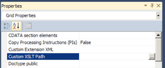
Note
You cannot use both an external XSLT style sheet and functoids within a single map.
For the purposes of testing, there are two basic types of maps:
Simple maps, which consist of a single source schema and single destination schema
Complex maps, which consist of two or more source schemas and/or two or more destination schemas
This solution will work through both types, illustrating several techniques for creating the necessary input documents and obtaining the test results. Figure 3-63 shows a simple map, with a Company schema being mapped from a combination of a Person schema and hard-coded values in two String Concatenate functoids.
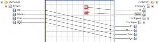
Use the following steps to test a simple map:
In the Solution Explorer, right-click the map to test and select Properties. The Property Pages dialog box contains the properties listed in Table 3-3.
Table 3.3. Map Properties
Description
Validate TestMap InputBoolean value indicating whether the source document will be validated against the source schema. For testing, it is often easiest to leave this to
Falsein the early stages of development.Validate TestMap OutputBoolean value indicating whether the output document should be validated against the destination schema. For testing, it is often easiest to leave this to
Falsein the early stages of development.TestMap Input InstancePath to the file that contains an instance of the source schema. Used when the
TestMap Inputproperty is not set toGenerate Instance.TestMap InputIndicates the origin of the source document. If set to
Generate Instance, BizTalk will generate an instance in memory that contains values for all attributes and elements in the source schema. If set toXMLorNative, BizTalk will look for an instance of the document in the location specified in theTestMap Input Instanceproperty.Nativeindicates a non-XML file, such as a flat file.TestMap OutputIndicates the format of the output document. The document will be output to a file stored in a temporary directory on Windows and accessible through Visual Studio.
Note
All test map output files are stored in the following directory:
$Documents and Settings[current user]Local SettingsTemp\_MapData.If you're testing with the
TestMap Inputproperty set toGenerate Instance, right-click the map, and select Test Map (see Figure 3-64). This will cause BizTalk to write to the Output window in Visual Studio and display any errors that may exist. If no errors exist in the map, a link to the test's output XML file will be made available.If you're testing with the
TestMap Inputproperty set toXMLorNative, and no instance currently exists, follow these steps:Right-click the source schema in the Solution Explorer, and select Properties. Set the path where an instance of the output document should be written. Click OK when the properties have been set appropriately.
Right-click the source schema, and select Generate Instance.
Open the document created in the previous step. BizTalk will give default values to all of the elements and attributes in the schema. Edit these with appropriate values for your testing needs. When you're generating instances from schemas, all
Anyelements andAnyattributes will be created. These will fail validation when a map is tested. Either delete these from the generated instance or replace them with a value that would be expected.Right-click the map in the Solution Explorer, and select Properties.
Set the
TestMap Input Instanceproperty to the path of the instance created in step 3c. Set theTest Map Inputproperty to the appropriate type. Click OK.Right-click the map, and select Test Map. This will produce an output document that can be validated for accuracy. Check the Output window in Visual Studio for details in case of failure.
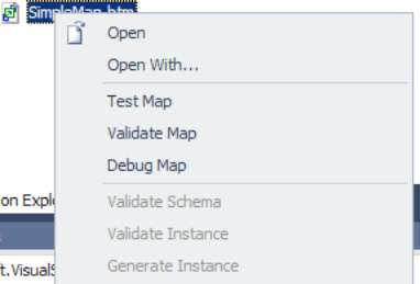
Testing complex maps requires several more steps to create a valid input instance. The main difference in testing the two types of maps lies in how the input instances are generated.
When a map has multiple source schemas, they are wrapped in a hierarchy created by BizTalk. This hierarchy must be matched if using anything other than Generate Instance for the TestMap Input. In cases where nodes such as Any elements or Any attributes exist in the source documents, generated instances will fail during testing. It then becomes a requirement to create by hand an instance of the multipart input document.
A map can have two or more source documents specified through the use of a Transform shape in a BizTalk orchestration (as shown in Figure 3-65).
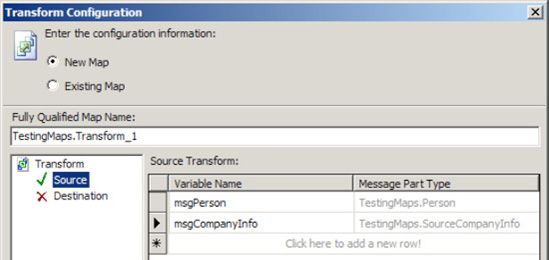
Figure 3-66 shows a complex map with a Company schema being mapped from a combination of two source schemas, Person and SourceCompanyInfo.
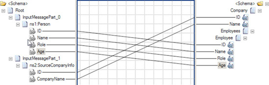
There is never a time in which multiple native instances can be set as source, since the only place that a map with multiple source schemas can be created is in a Transform shape within an orchestration. Therefore, the following steps are specific to creating XML instances that match the multipart input instance needed and can be taken to aid in producing a valid source instance:
To generate an instance of the source schema, create a temporary map that is the inverse of what you are trying to produce. In the case of the example shown in Figure 3-67, the map would consist of the
Companyschema being the single source schema, with thePersonandSourceCompanyInfobeing the two destination schemas. The intention is to have BizTalk generate an output message that closely resembles the needed input instance. When namespaces are involved, this is all the more important, as prefixes will be added by BizTalk when creating the multipart message. Figure 3-67 illustrates the inverse mapping.Once a temporary map has been created, right-click the map in the Solution Explorer, and select Properties. Check that the
TestMap Inputproperty is set toGenerate Instance.Right-click the map in the Solution Explorer, and select Test Map. This will produce an output document. The output of the map shown in Figure 2-69 is shown in Listing 3-44.
Example 3.44. Output of the Inverse Map
<ns0:Root xmlns:ns2="http://TestingMaps.SourceCompanyInfo"
xmlns:ns0="http://schemas.microsoft.com/BizTalk/2003/aggschema"
xmlns:ns1="http://TestingMaps.Person">
 <OutputMessagePart_0>
  <ns1:Person>
   <ID>ID_0</ID>
   <Name>Name_0</Name>
   <Role>Role_0</Role>
   <Age>Age_0</Age>
  </ns1:Person>
 </OutputMessagePart_0>
 <OutputMessagePart_1>
  <ns2:SourceCompanyInfo>
   <ID>ID_0</ID>
   <CompanyName>Name_0</CompanyName>
  </ns2:SourceCompanyInfo>
 </OutputMessagePart_1>
</ns0:Root>
Copy the output document into a text editor, and manually change the names of the
OutputMessagenodes toInputMessagenodes so that the outcome is a valid instance of the input document for the true map. In this case, you want a document that can be used as the input for the map shown in Figure 3-66, as shown in Listing 3-45. The bold elements in the example are the only elements that need to be modified.Example 3.45. Input Instance Produced by Modifying Output from Listing 3-44
<ns0:Root xmlns:ns2=http://TestingMaps.SourceCompanyInfo
xmlns:ns0="http://schemas.microsoft.com/BizTalk/2003/aggschema"
xmlns:ns1="http://TestingMaps.Person">
<InputMessagePart_0>
<ns1:Person>
<ID>ID_0</ID>
<Name>Name_0</Name>
<Role>Role_0</Role>
<Age>Age_0</Age>
</ns1:Person>
</InputMessagePart_0>
<InputMessagePart_1>
<ns2:SourceCompanyInfo>
<ID>ID_0</ID>
<CompanyName>Name_0</CompanyName>
</ns2:SourceCompanyInfo>
</InputMessagePart_1>
</ns0:Root>
Once the modifications have been made to the document, save it to a file. This document can now be used as a valid input instance for the valid map (you can delete the temporary map at this time). Right-click the valid map in the Solution Explorer, and select Properties. Set the
TestMap Inputproperty toXMLandTestMap Input Instanceto the file that you just created.Right-click the map in the Solution Explorer, and select Test Map. This will produce an output document that can be validated for accuracy. Check the Output window in Visual Studio for details in case of failure.
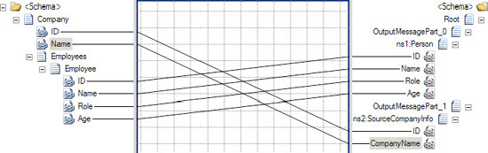
The difficulty in testing maps lies in the creation of the source schema instances. There are a number of ways in which these instances can be created. The objective of this solution was to provide the steps necessary for creating documents that would allow for the testing of both simple maps and complex maps. Additionally, the steps necessary for producing the test output were described.
Debugging a map can be done using the following steps:
Specify an input document to test the map with (right-click the map, and set it in the properties).
In the Solution Explorer, right-click the map to debug, and select Debug Map (see Figure 3-68).
Immediately, the map will open in a classic debugger. You can set breakpoints in the XSL that is shown (see Figure 3-69).
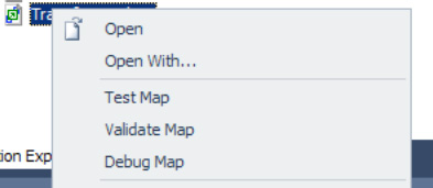
Debugging a map is very straightforward, and can be useful in many situations. With some maps, such as Inline XSLT Call Templates, the debugger is not of much use, but for the majority of cases, it can be very helpful. Prior to BizTalk 2010, there were some techniques to debug the map, but they were not as readily available and easy to implement. Standard debug shortcuts apply, including
F10 to step over the code
F11 to step into the code (includes stepping into inline scripts, such as C#, and functoids)
F9 to toggle a breakpoint
F5 to continue