
C H A P T E R 5
Software Architecture
What do we mean by a software architecture? To me the term architecture conveys a notion of the core elements of the system, the pieces that are difficult to change. A foundation on which the rest must be built.
—Martin Fowler1
Once you have an idea of what you're going to build, then you can start thinking about how you're going to build it. Of course, you've already been thinking about this from the very first requirement, but now you have permission to do it. Now we begin to delve into design.
There are really two levels of software design. The level we normally think of when we're writing programs is usually called detailed design. What operations do we need? What data structures? What algorithms are we using? How is the database going to be organized? What does the user interface look like? What are the calling sequences? These are all very detailed questions that need to be answered before you can really get on with the detailed work of coding (well, sort of – we'll get to that later).
But there's another level of design. This kind of design is all about style. If you were building a house, this design level asks questions like ranch or multi-story? Tudor or Cape Cod? Which direction do the bedroom windows face? Forced-air or hot-water heat? Three bedrooms or four? Open concept floor plan or closed? These questions focus somewhat on details, but they are much more about the style of the house and how you'll be using it, rather than things like 12 or 14 gauge wire for the electrical system or the diameter of the air conditioning ductwork. This emphasis on style is what software architecture is all about. As Fowler says in this chapter's opening quote, you need the foundation before you can build the rest of the structure. Software architecture is a set of ideas that tells you which foundation is the right one for your program.
The idea of software architecture began as a response to the increasing size and complexity of programs. “As the size and complexity of software systems increases, the design problem goes beyond the algorithms and data structures of the computation: designing and specifying the overall system structure emerges as a new kind of problem.... This is the software architecture level of design.”2 However it is really the case that all programs of any size and complexity have an architecture. It's just that for larger programs you need to be more intentional about your thinking about the architecture to make sure you have the right set of architectural patterns incorporated in your system design. You need to do this. It's so much harder to change things at the architectural level once the program has been written, because architectural features are so fundamental to the structure of the program.
____________________________
1 “Is Design Dead?” Retrieved from http://martinfowler.com/articles/designDead.html
2 Garlan, D. and M. Shaw (1994). An Introduction to Software Architecture. Pittsburgh, PA: Carnegie Mellon University: 49. CMU/SEI-94-TR-21. (1994)
There are many different styles of software architecture, and in any given project you'll probably use more than one. The architectural style used for a program depends on what it is you're doing. As we'll see, different types of programs in different domains will lead us to different architectural styles; we can also call these architectural patterns since they have many characteristics of the design patterns we'll see shortly. First let's get some general vocabulary under our belts.
General Architectural Patterns
Whenever a software architect starts thinking about an architecture for a program, she usually starts by drawing pictures. Diagrams of the architecture allow people to see the structure and framework of the program much more easily than text. Software architectures are normally represented as black box graphs where graph nodes are computational structures and the graph edges are communication conduits between the structures. The conduits can represent data flow, object message passing, or procedure calls. Notations of this type vary and there are several standard notations, notably the United Modeling Language (UML). Visual descriptions of architectures are generally easier to understand. A particular architectural style is a pattern that can represent a set of similar structures. Let's looks at several different common architectural styles.
Pipe-and-filter Architecture
In a pipe-and-filter style architecture, the computational components are called filters and they act as transducers that take input, transform it according to one or more algorithms, and then output the result to a communications conduit. The input and outputs conduits are called pipes.
A typical pipe-and-filter architecture is linear, as in Figure 5-1.
Figure 5-1. The pipe-and-filter architecture
The filters must be independent components. That is one of the beauties of a pipe-and-filter architecture. You can join different filters in the set in different arrangements in order to get different results. The classic example of a pipe-and-filter architectural style is the Unix shell, where there are a large number of small programs that typically do a single thing and can be chained together using the Unix pipe mechanism. Here's an example that shows how a pipe-and-filter can work. This problem is from Jon Bentley's book Programming Pearls.3
_______________________
3 Bentley, J. Programming Pearls, Second Edition. (Boston, MA: Addison-Wesley, 2000.)
The Problem: Given a dictionary of words in English, find all the anagrams in the dictionary. That is, find all the words that are permutations of each other. For example, “pots,” “stop,” and “spot” are anagrams of each other.
So what do we know? Well, first of all, all the anagrams have the same letters and the same number of letters in each word. That gives us the clue to the method you'll use to find the anagrams. Got it yet? Don't worry; I'll wait.
Yes! If you sort each word, you'll end up with a string of characters that has all the letters in the word in alphabetical order. We call this creating a sign for the word. If you then sort the resulting list, all the anagrams will end up together in the sorted list because their sorted letters will be identical. If you then keep track of which words you sorted, you can then simplify the list and create a new list with, say, each set of anagrams on the same line of the output file. This is exactly how Bentley does it.
But how does this relate to a pipe-and-filter architecture, you ask? Good question. Let's break down the solution again.
- Create a sign for each word in the list by sorting the letters in each word; keep the sign and the word together.
- Sort the resulting list by the signs; all the anagrams should now be together.
- Squash the list by putting each set of anagrams on the same line, removing the signs as you do.
See the pipe-and-filter now? In Unix-speak it looks like this:
sign <dictionary.txt | sort | squash >anagrams.txt
where sign is the filter we use to do step 1, with input file dictionary.txt. sign outputs a list of signs and their associated words which is piped to the Unix sort utility (we didn't need to write that one). Sort then sorts the list by the first field on each line (its default behavior), which happens to be the sign of each word. It then outputs the sorted list to the next pipe. Squash takes the sorted list from the incoming pipe and compresses it by putting all the words with the same sign on the same line, eliminating the signs as it does so. This final list is sent via one last pipe (this time a Unix I/O redirection) to the output file anagrams.txt.
Note that this example has all the features of a standard pipe-and-filter architecture: independent computational components that perform a transformation on their input data and communication conduits that transmit the data from the output of one component to the input of the next. Note also that not all applications should use the pipe-and-filter architecture. For example, it won't work so well for interactive applications or applications that respond to events or interrupts. That's why we're going to look at more architectural styles.
An Object-Oriented Architectural Pattern
The advent of object-oriented analysis, design, and programming in the early 1980s (well, it really started in the ‘60s, but no one was paying attention) brought with it a number of architectural and design patterns. We'll just focus on one object-oriented architectural pattern here and save discussions of the rest to the chapter on Design Patterns.
The Model-View-Controller (MVC) architectural pattern is a way of breaking an application, or even just a piece of an application's interface, into three parts: the model, the view, and the controller. MVC was originally developed to map the traditional input, processing, output roles of many programs into the GUI realm:
Input
Processing
Controller
The user input, the modeling of the external world, and the visual feedback to the user are separated and handled by model, view and controller objects, as shown in Figure 5-2.
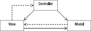
Figure 5-2. The Model-View-Controller architecture
- The controller interprets mouse and keyboard inputs from the user and maps these user actions into commands that are sent to the model and/or viewport to effect the appropriate change.
- The model manages one or more data elements, responds to queries about its state, and responds to instructions to change state. The model knows what the application is supposed to do and is the main computational structure of the architecture – it models the problem you're trying to solve.
- The view or viewport manages a rectangular area of the display and is responsible for presenting data to the user through a combination of graphics and text. The view doesn't know anything about what the program is actually doing; all it does is take instructions from the controller and data from the model and displays them. It communicates back to the model and controller to report status.
The flow of an MVC program typically looks like this:
- The user interacts with the user interface (e.g., the user presses a button) and the controller handles the input event from the user interface, often via a registered handler or callback. The user interface is displayed by the view but controlled by the controller. Oddly enough, the controller has no direct knowledge of the view as an object; it just sends messages when it needs something on the screen updated.
- The controller accesses the model, possibly updating it in a way appropriate to the user's action (e.g., controller causes the user's shopping cart to be updated by the model). This usually causes a change in the model's state as well as in its data.
- A view uses the model to generate an appropriate user interface (e.g., view produces a screen listing the shopping cart contents). The view gets its own data from the model. The model has no direct knowledge of the view. It just responds to requests for data from whomever and to requests for transforming data from the controller.
- The controller, as the user interface manager, waits for further user interactions, which begins the cycle anew.
The main idea here is separation of concerns – and code. The objective is to separate how your program works from what it is displaying and how it gets its input data. This is classic object-oriented programming; create objects that hide their data and hide how they manipulate their data and then just present a simple interface to the world to interact with other objects. We'll see this again in Chapter 9.
An MVC Example: Let's Hunt!
A classic example of a program that uses the MVC architectural pattern is the Nifty Assignment presented by Dr. David Matuszek at the 2004 SIGCSE Technical Symposium.4
The Problem
The program is a simple simulation of a fox and a rabbit. The fox is trying to find the rabbit in a grid environment, and the rabbit is trying to get away. There are bushes that the rabbit can hide behind and there are some restrictions on movement.
Figure 5-3 is a typical picture of the game in action.
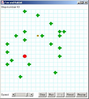
Figure 5-3. A typical fox and rabbit hunt instance
4 Matuszek, David. “Rabbit Hunt,” SIGCSE 2004 Technical Symposium, Nifty Assignments Session, retrieved August 17, 2009, http://nifty.stanford.edu/2004/RabbitHunt/. (2004)
The fox is the large dot, the rabbit is the small dot, and the bushes are the fat crosses.
The objective of the programming assignment is to make the rabbit smarter so it can escape from the fox. We don't really care about this; we want to look at how the program is organized. Figure 5-4 shows the organization of the program. It's a UML object diagram taken from the BlueJ IDE. The key parts of the program are the three classes, Model, View, and Controller.
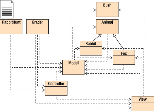
Figure 5-4. The fox and rabbit hunt class structure
Model
The model represents the rules of the game. It does all the computation, all the work of deciding whose turn it is, what happens during each turn, and whether anyone has won. The model is strictly internal and has practically nothing to do with the other parts of the program.
View
The view displays what is going on. It puts an image on the screen so the user can see what is happening. The view is completely passive; it does not affect the hunt in any way, it's just a news reporter that gives you a (partial) picture of what is happening inside the model.
Controller
The controller is the part of the program that displays the controls (the five buttons and the speed controls at the bottom of the window). It knows as little as possible about the model and view; it basically tells the model when to go and when to stop.
Model
The model part of this program is actually composed of five classes: Model (the “main” model class), Animal, Rabbit, Fox, and Bush. Rabbit and Fox are subclasses of Animal (as you can see from the solid arrows in the UML diagram). This is the part of the program that you really need to understand.
The RabbitHunt class just creates model, view, and controller objects, and turns control over to the controller object. The controller object starts the model object, and then just waits for the user to press a button. When a button is pressed, a message is sent to the model object, which decides what to do.
The model object
- places the fox, rabbit, and bushes in the field;
- gives the rabbit and the fox each a chance to move (one moves, then the other; they don't both move at the same time);
- tells the view to display the result of these two moves; and
- determines which animal won.
The advantages of breaking the program up into these separate parts are many. We can safely rewrite the GUI in the Controller object or the display in the view object without changing the model. We can make the fox and/or the rabbit smarter (or dumber!) without changing the GUI or the display. We can re-use the GUI for a different application with very little effort. The list just goes on.
In short, MVC is your friend; use it wisely and often.
The Client-Server Architectural Pattern
Moving to a more traditional architecture we go back in time. Once upon a time all programs ran on big iron and your entire program ran on a single machine. If you were lucky enough to be using a time-shared operating system, several people could be using the same program – albeit usually different copies – simultaneously. Then came personal computers and networks. And someone had the bright idea of dividing the work up between that big iron and your puny desktop machine. Thus was born the client-server architecture.
In a client-server architecture, your program is broken up into two different pieces that typically run on two separate computers. A server does most of the heavy lifting and computation; it provides services to its clients across a high-bandwidth network. Clients, on the other hand, mostly just handle user input, display output, and provide communication to the server. In short, the client program sends requests for services to the server program. The server program then evaluates the request, does whatever computation is necessary (including accessing a database, if needed) and responds to the client's request with an answer. The most common example of a client-server architecture today is the World Wide Web.
In the web model, your browser is the client. It presents a user interface to you, communicates with a web server, and renders the resulting web pages to your screen. The web server does a number of things. It serves web pages in HTML, but it also can serve as a database server, a file server, and a computational server – think about everything that Amazon.com does when you access that web site.
Clients and servers don't have to be on different computers, though. Two examples of programs written using a client-server architecture where both sides can reside on the same computer are print spoolers and the X Windows graphical system.
In a print spooler application, the program you are running – a word processor, a spreadsheet program, your web browser – runs as a client that makes request to a printing service that is implemented as a part of the computer's operating system. This service is typically known as a print spooler because it keeps a spool of print jobs and controls which jobs get printed and the order of their printing. So from your word processor, you'll select Print from a menu, set certain attributes and often pick a printer, and then click OK on some dialog box. This sends a print request to the print spooler on your system. The print spooler then adds your file to a queue of print jobs that it manages, contacts the printer driver and makes requests for printing to occur. The difference here is that once you've clicked the OK button, your client program (the word processor) typically does not have any more contact with the print spooler, the print service runs unattended.
The X Window System (see www.xfree86.org/) is a graphical windowing system used on all Unix and Linux based systems and also available for Apple Macintosh and Microsoft Windows systems as an add-on windowing system. The X system uses a client-server architecture where the client programs and the server typically both reside on the same computer. The X system server receives requests from client programs, processes them for the hardware that is attached to the current system, and provides an output service that displays the resulting data in bitmapped displays. Client program examples include xterm – a windowed terminal program that provides a command line interface to Unix, xclock – you guessed it – a clock, and xdm the X Window display manager. The X system allows hierarchical and overlapping windows, and provides the ability to configure menus, scroll bars, open and close buttons, background and foreground colors, and graphics. X can also manage a mouse and keyboards. These days the main use of the X system is as a springboard to build more sophisticated window managers, graphical environments, graphical widgets, and desktop management windowing systems like GNOME and KDE.
The Layered Approach
The layered architectural approach suggests that programs can be structured as a series of layers, much like geologic strata, with a sequence of well-defined interfaces between the layers. This has the effect of isolating each layer from the ones above and below it, so that one can change the internals of any layer without having to change any of the other layers in the program. That is, as long as your changes don't involve any changes to the interface. In a layered approach, interfaces are sacred. Two classic examples of a layered approach to programming are operating systems (OSs) and communications protocols.
An operating system's architecture has several objectives, among them to centralize control of the limited hardware resources and to protect users from each other. A layered approach to the operating system architecture does both of these things. Take a look at a pretty standard picture of an OS architecture (see Figure 5-5).
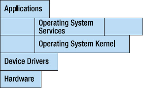
Figure 5-5. A layered architecture
In this layered model, user applications request operating system services via a system call interface. This is normally the only way for applications to access the computer's hardware. Most operating system services must make requests through the kernel and all hardware requests must go through device drivers that talk directly to the hardware devices. Each of these layers has a well-defined interface, so that, for example, a developer may add a new device driver for a new disk drive without changing any other part of the OS. This is a nice example of information hiding.
The same type of interface happens in a communications protocol. The most famous of these layered protocols is the International Standards Organization (ISO) Open Systems Interconnection (OSI) seven-layer model. This model looks like Figure 5-6.
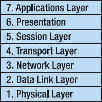
Figure 5-6. The ISO-OSI layered architecture
In this model, each layer contains functions or services that are logically similar and are grouped together. An interface is defined between each layer and communication between layers is only allowed via the interfaces. A particular implementation need not contain all seven layers, and sometimes two or more layers are combined to make a smaller protocol stack. The OSI model defines both the seven-layer approach and all the interface protocols. The model can be downloaded as a PDF file from http://www.itu.int/rec/T-REC-X.200/en. (The ITU or International Telecommunications Union is the new name for the ISO.)
Examples of protocols that are implemented at each layer are shown in Table 5-1.
Table 5-1. Example Layered Protocols Using the ISO-OSI Architecture
| Layer | Protocol |
| 7. Application | http, ftp, telnet |
| 6. Presentation | MIME, SSL |
| 5. Session | Sockets |
| 4. Transport | TCP, UDP |
| 3. Network | IP, IPsec |
| 2. Data Link | PPP, Ethernet, SLIP, 802.11 |
| 1. Physical |
The Main Program: Subroutine Architectural Pattern
The most traditional and oldest architectural pattern is the main program – subroutine pattern. While it descends from Niklaus Wirth's 1971 paper “Program Development by Stepwise Refinement,”5 Wirth was just the first to formally define the top-down problem decomposition methodology that naturally leads to the main program – subroutine pattern.
The idea is simple. You start with a big problem, and then try to decompose the problem into several smaller problems or pieces of the original problem. For example, nearly every problem that is amenable to solution by top-down decomposition can be divided into three parts immediately – input processing, computation of the solution, and output processing.
Once you have a problem divided into several pieces, you look at each piece individually and continue dividing, ignoring all the other pieces as you go. Eventually, you'll have a very small problem where the solution is obvious; now is the time to write code. So you generally solve the problem from the top down, and write the code from the bottom up. There are many variations, however.
To quote from the conclusion to Wirth's paper:
- Program construction consists of a sequence of refinement steps. In each step a given task is broken up into a number of subtasks. Each refinement in the description of a task may be accompanied by a refinement of the description of the data which constitute the means of communication between the subtasks...
- The degree of modularity obtained in this way will determine the ease or difficulty with which a program can be adapted to changes or extensions of the purpose...
- During the process of stepwise refinement, a notation which is natural to the problem in hand should be used as long as possible... Each refinement implies a number of design decisions based upon a set of design criteria...
- The detailed elaborations on the development of even a short program form a long story, indicating that careful programming is not a trivial subject.
5 Wirth, N. “Program Development by Stepwise Refinement.” Communications of the ACM 14(4): 221-227. (1971)
Figure 5-7 gives an impression about how the main program subroutine architecture works. We'll discuss top-down decomposition of problems much more in Chapter 7.
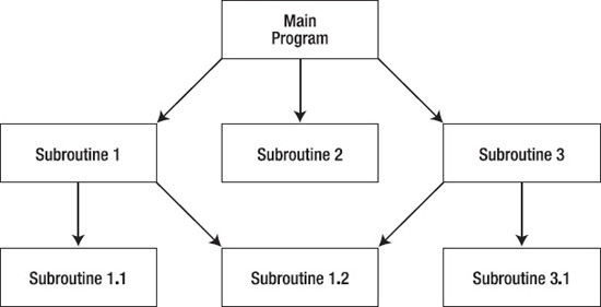
Figure 5-7. A main program – subroutine architecture
Conclusion
The software architecture is the core of your application. It is the foundation on which you build the rest of the program. It drives the rest of your design. There are many different styles of software architecture and in any given project you'll probably use more than one. The architectural style used for a program depends on what it is you're doing. That's the beauty of these styles; it may not always be true that form follows function, but for software – design follows architecture. These foundational patterns lead you down the path of design, shaping how your program will be constructed and lived in. Go out there and build a great program.
References
Bentley, J. Programming Pearls, Second Edition. (Boston, MA: Addison-Wesley, 2000.)
Garlan, D. and M. Shaw (1994). An Introduction to Software Architecture. Pittsburgh, PA: Carnegie Mellon University: 49. CMU/SEI-94-TR-21. (1994)
Kernighan, B. W. and R. Pike. The Practice of Programming. (Boston, MA: Addison-Wesley, 1999.)
Matuszek, David. “Rabbit Hunt,” SIGCSE 2004 Technical Symposium, Nifty Assignments Session, retrieved August 17, 2009, http://nifty.stanford.edu/2004/RabbitHunt/. (2004)
McConnell, S. Code Complete 2. (Redmond, WA: Microsoft Press, 2004.)
Wirth, N. “Program Development by Stepwise Refinement.” Communications of the ACM 14(4): 221-227. (1971)