Chapter 4
UDK Collisions
In this chapter we will cover UDK physics. The Unreal Engine features a physics engine based on the Novodex PhysX system that calculates collisions for rigid bodies based on the shape of a collision mesh. Contact points with other objects using these collision meshes are generated by the physics engine in order to produce an accurate physics simulation.
We will be learning the Unreal Physics system through a series of fun hands-on tutorials where you will learn such things as:
- How to create a KActor from a static mesh asset and making it move by applying a force to it
- How to create a KAsset from a skeletal mesh asset and making it move by applying a force to it
- How to create physics constraint that will bind different objects together using the Unreal Editor
- How to create a placeable rigid body that can be placed in a level using the Unreal Editor
- How to make an exploding wall of blocks
Collision Meshes
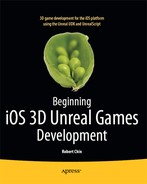
Collision models or collision meshes are what the physics engine uses in rigid body physics collisions. Collision meshes are critical to the behavior of an object when it collides with another object or the ground. For example, you will notice in the following tutorials that a sphere rolls across the floor of the arena while the cube does not. The difference in the behavior is caused by the structure of the collision meshes. Let’s compare a collision mesh for a Cube and the collision mesh for a Sphere. The collision mesh for a Cube is also a cube in structure as indicated in Figure 4–1 of a Cube mesh in the Static Mesh Editor.
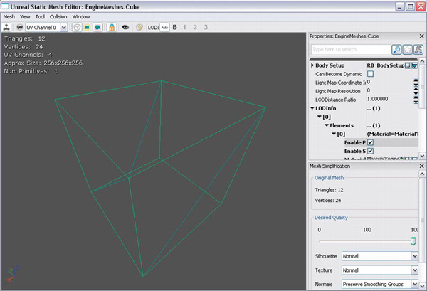
Figure 4–1. Cube Static Mesh in Static Mesh Editor (Viewing collision mesh and the cube as a wireframe)
For a Sphere (see Figure 4–2), the collision mesh is, of course, spherical and differs from a Cube in the same way a physical ball differs from a block. As in the real world, the different shapes behave differently when colliding with other objects.
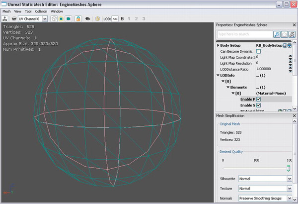
Figure 4–2. Sphere Collision Mesh in Static Mesh Editor (Viewing collision mesh and sphere as a wireframe)
The collision mesh generally follows the shape of the static mesh and must be convex not concave. In convex meshes all parts of the mesh are outward bending and there are no holes in the mesh. Concave meshes may have holes in them and have parts that are inward bending. You are not limited to a specific set of collision meshes. You can create your own collision meshes through a separate, free 3D modeling program like Blender available at http://www.blender.org. These meshes must be prefixed with “UCX_” which is called a “Convex Mesh Primitive” and match a corresponding regular mesh. For example, in Blender the mesh “UCX_Cube” would be the collision mesh for the mesh named “Cube”. These two meshes would be placed one on top of the other so that they line up perfectly. They then would be exported in a format such as .fbx that can be imported into the Unreal UDK. The collision mesh can then be viewed in the Unreal Static Mesh Editor after selecting View ![]() Collision from the menu.
Collision from the menu.
You can also use the feature in the Unreal Static Mesh Editor called K-DOP to generate simple collision meshes for your static mesh. However, this method is only good for a very rough collision mesh and may not be suitable for your needs. This may be especially true if you are building a physics-type game like Angry Birds that may require more precise collision detection.
NOTE: Other graphics programs that can create UDK-compatible content are 3D Studio Max and Maya. Trial versions are available that last 30 days and are fully compatible.
For more information on 3d Studio Max go to:
http://usa.autodesk.com/3ds-max/
For more information on Maya go to:
Collision Objects
When simulating realistic collisions are concerned, the UDK has two main types of collision objects which are the KActor and KAsset. This section will give you a basic overview of the KActor and KAsset. Also, in the hands-on examples in this section, you will:
- Create a new KActor and apply a force to it
- Create a new KAsset and apply a force to it
KActor and KAsset Overview
In terms of meshes in the UDK system there are static meshes and skeletal meshes. Static meshes are meshes that have no bones or any flexible skeletal structure such as doors, gates, blocks, rocks, and chairs. Skeletal meshes are meshes that have bones and a skeletal structure such as characters, ropes, wires, and chains.
In terms of rigid body collisions there are two types of objects KActors and KAssets. KActors contain static meshes and can be used by the physics engine for realistic rigid body collisions using the KActor’s collision mesh. KAssets contain skeletal meshes that can be used by the physics engine for realistic rigid body collisions using the mesh’s collision areas that are set up in Unreal Phat. KActors and KAssets are placeable which mean that objects of these classes can be placed into a level using the Unreal Editor. You can also dynamically create new KActors and KAssets during a game but you must use the KActorspawnable class for KActors and the KAssetspawnable class for KAssets.
Creating CustomKActors and KAssets
You can create custom KActors and KAssets by creating a new class that derives from a KActor or KAsset. For example, the following class RigidBodyCube derives from the Kactor class (see Listing 4–1). In the defaultproperties a new StaticMeshComponent is created and named RigidBodyCubeMesh. The actual mesh is defined by the variable StaticMesh. The RigidBodyCubeMesh is then set as the StaticMeshComponent for this KActor and added to the Actor’s Components array which ties this mesh to the KActor’s location and rotation.
Listing 4–1. Deriving a class from the KActor class
class RigidBodyCube extends Kactor

defaultproperties

{

    Begin Object Class=StaticMeshComponent Name=RigidBodyCubeMesh

        StaticMesh=StaticMesh'EngineMeshes.Cube'

    End Object

    StaticMeshComponent=RigidBodyCubeMesh

    Components.Add(RigidBodyCubeMesh)

}
An example of a class deriving from a Kasset is the class RopeSection that derives from a dynamic Kasset class KAssetspawnable (see Listing 4–2).A new SkeletalMeshComponent called RopeSection is created in the defaultproperties block. Here we define the SkeletalMesh and the PhysicsAsset that are used for this skeletal mesh component. RopeSection is then set as the SkeletalMeshComponent for this object and added to the Components array.
Listing 4–2. Deriving a class from KAssetspawnable
class RopeSection extends KAssetspawnable;

defaultproperties

{

    Begin Object Class=SkeletalMeshComponent Name=RopeSection

        SkeletalMesh=SkeletalMesh'physics_assets.SKM_Wire'

        PhysicsAsset=PhysicsAsset'physics_assets.SKM_Wire_Physics_02'

    End Object

    SkeletalMeshComponent=RopeSection

    Components.Add(RopeSection)

}
However, before we can get these KActors and KAssets to collide we need to set the collision parameters. Collision parameters are discussed later in this chapter. For now, we just wanted to introduce how you would create the general framework for a new physics object.
Applying a Force to a KActor and KAsset
In terms of applying a force to a KActor you can use the ApplyImpulse() function located in the KActor class. The ApplyImpulse() function declaration is as follows and takes in an impulse direction, impulse magnitude, and the location where to apply this force as required parameters.
ApplyImpulse(Vector ImpulseDir,

              float ImpulseMag,

              Vector HitLocation,

              optional TraceHitInfo HitInfo,

              optional class<DamageType> DamageType );
For a KAsset you must apply a force to the KAsset’s SkeletalMeshComponent by using the AddImpulse() function. The actual function is located in the PrimitiveComponent class and has a declaration as follows. The Impulse parameter contains both the magnitude and direction of the force. The Position is the location where to apply the force in world space. The BoneName is the bone to apply the force to if this is a skeletal mesh. If bVelChange is True, then the Impulse will be interpreted as the change in velocity instead of a force and the mass of this object will have no effect.
AddImpulse(vector Impulse,

            optional vector Position,

            optional name BoneName,

            optional bool bVelChange);
The following examples illustrate how to apply a force to a Kactor and a Kasset.
Hands-on Example: Creating a KActor and applying a force to it
In this tutorial you will be creating a KActor from a static mesh asset using the Unreal Editor and placing this Kactor in a new level. You will then be able to apply a force to this actor by clicking on it with your mouse from within the Mobile Previewer.
Creating a new Level with KActors
The first thing you need to do is create a new level in the editor and add some KActors to the level. Follow these steps to add a sphere:
- Bring up the Unreal Editor and the default level should pop up.
- Create a new level by clicking on the File
 Save As menu item to save the current map as a different file. When the file Save As dialog box opens, type in Example41Map for the filename and click Save. This should save your map into the
 UDKUDK-2011-06UDKGameContentMapsdirectory by default. - Next you need to create a KActor from a static mesh. Set your Packages section located in the lower-left-hand corner of the Content Browser to Engine.
- Check the Static Meshes checkbox under the Object Types Favorites section and type Sphere in the search bar above that.
- Click on the static mesh called Sphere.
- Right-click on an empty space in the level where you want to place this mesh and select Add Rigid Body:EngineMeshes.Sphere from the context menu (see Figure 4–3). This will place your new rigid body into the level.

- The first thing you may notice is that the sphere is way too big. In order to make this sphere smaller as well as do some initial setup double-click on the sphere to bring up its properties (see Figure 4–4).
Figure 4–4. Properties of new KActor formed from static mesh
- Under the KActor category click on “Wake On Level Start” checkbox to begin the physics simulation for this object when the level starts.
- Under the Display Category change the “Draw Scale” by clicking on its input field and changing the number 1 to .10. This shrinks the size of the sphere to one tenth of its original size. You may also have to reposition the sphere so that is above ground by clicking on the up (Z Axis) of the sphere transformation widget (see Figure 4–5) and dragging the sphere upward so that it does not penetrate the ground.
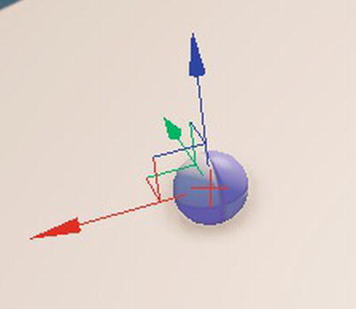
Figure 4–5. Sphere transformation widget
Next, let’s add a cube to the level using the same process we used for the sphere.
- Change the asset search term to cube. You should see a static mesh called TexPropCube.
- Select this asset by clicking on it with the left mouse button.
- Place this mesh into your game level using the same procedure you used with the sphere: Right-click on the level where you want to place the cube and select Add Rigid Body: EditorMeshes.TexPropCube (see Figure 4–6).

- Again, the cube will be very big so double-click on the cube to bring up the KActor’s properties.
- Just as with the sphere check the Wake on Level Start checkbox under the KActor properties and change the Draw Scale property under the Display category to .10.
- Move the cube using the object’s transformation widget so that it is completely above ground and positioned where you want it. The transformation widget is the set of axes located at the object’s center. Click and drag the X, or Y transformation axis to move the object around the arena and the Z axis to move the object up and down.
- Now, save the level by selecting the File Save All option. Figure 4–7 shows the level with the two objects added.
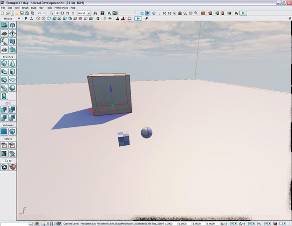
Figure 4–7. Final level with resized sphere and cube rigid bodies
Creating the Unreal Script Code
The next thing we need to do is create a new folder for this example called ExampleCh41 and another folder under that called Classes at C:UDKUDK-2011-06DevelopmentSrc under your UDK installation directory. This is where your source code files will be placed. Create a new file called ExampleCh41Game .uc and save it to your newly created folder. Save the file under the ExampleCh41Game Classes directory you just created.
Custom Game Type
To define the game type for this example, enter the code that follows into the file. Note that instead of providing a large block of code at once, I’m going to walk through it a piece at a time. Just add each new piece as we discuss it, or you can find the full code in the book’s source code.
The following declares a class ExampleCh41Game that derives from FrameworkGame. This class defines what kind of game we will be playing:
The function OnEngineHasLoaded() is called once the Unreal Engine has started and outputs a message stating that this new game type is now active.
event OnEngineHasLoaded()

{

    WorldInfo.Game.Broadcast(self," ExampleCh41Game  Type Active - Engine Has Loaded

!!!!");

}
The PreventDeath function returns True indicating that the player can not die in this game type.
function bool PreventDeath(Pawn KilledPawn, Controller Killer, class<DamageType>

DamageType, vector HitLocation)

{

    return true;

}
The SetGameType function returns the current game type.
static event class<GameInfo> SetGameType(string MapName, string Options, string Portal)

{

    return super.SetGameType(MapName, Options, Portal);

}
In the defaultproperties section take special note that the PlayerControllerClass points to our custom player controller class ExampleCh41PC located in the ExampleCh41 directory. We will create the ExampleCh41PC class later.
defaultproperties

{

    PlayerControllerClass=class'ExampleCh41.ExampleCh41PC'


    DefaultPawnClass=class'UDKBase.SimplePawn'

    HUDType=class'UDKBase.UDKHUD'


    bRestartLevel=false

    bWaitingToStartMatch=true

    bDelayedStart=false

}
We have just finished creating a class that defines our custom game. The HUDType variable is set to the default class needed to display the mobile input controls. We will learn how to customize the HUD or Heads Up Display in Chapter 6.
In the next section we specify a custom Player Controller which determines exactly how the player interacts with the game.
Custom Player Controller
The next class we need to create is our custom player controller class. It is in this class we create code where the player can touch a KActor and apply a force to that KActor.
You will need to create a new plain text file called ExampleCh41PC in the same directory as the previous UnrealScript file. Enter the following code into this new file and save it. Again, we’ll go through the code a piece at a time.
The ExampleCh41PC class is derived from SimplePC and is the class that is responsible for processing the input from the player. PC is short for “Player Controller”.
class ExampleCh41PC extends SimplePC;
PickDistance holds the maximum distance that the picked object can be from the player.
var float PickDistance;
The ApplyForceRigidBody() function is where the force is actually applied to the rigid body object. See Listing 4–3.
Listing 4–3. Applying a Force to a Rigid Body
function ApplyForceRigidBody(Actor SelectedActor,

                              Vector ImpulseDir,

                              float ImpulseMag,

                              Vector HitLocation)

{

    if (SelectedActor.IsA('KActor'))

    {

        WorldInfo.Game.Broadcast(self,"*** Thrown object " @ SelectedActor @

                                               ", ImpulseDir = " @ ImpulseDir @

                                               ", ImpulseMag = " @ ImpulseMag @

                                               ", HitLocation = " @ HitLocation);

        KActor(SelectedActor).ApplyImpulse(ImpulseDir,ImpulseMag, HitLocation);

    }

    else

    {

        WorldInfo.Game.Broadcast(self,"!!!ERROR Selected Actor " @ SelectedActor @

                                              " is not a KActor, you can not apply an

impulse to this object!!!");

    }

}
The function takes a reference to an Actor and first tests the Actor to see if it is a KActor class object. This is done through the IsA() function which is defined in the Object class. The IsA() function returns True if the reference refers to an object of the KActor class.
If the Actor is a KActor then the KActor’s class function ApplyImpulse() is called to apply an impulse to the KActor object. In this case we are applying an impulse to the SelectedActor object. In order to do this we must first convert the SelectedActor object (which is defined as a reference to an Actor) to a KActor by casting it. This is possible because KActor is a subclass of Actor. The ApplyImpulse function takes as input the force direction, the amount of the force, and the location on the object where the force is applied.
The PickActor() function does the actual work of selecting an actor in the 3d game world based on a screen input from the iOS device. See Listing 4–4.
function Actor PickActor(Vector2D PickLocation, out Vector HitLocation, out TraceHitInfo

HitInfo)

{

    local Vector TouchOrigin, TouchDir;

    local Vector HitNormal;

    local Actor  PickedActor;

    local vector Extent;


    //Transform absolute screen coordinates to relative coordinates

    PickLocation.X = PickLocation.X / ViewportSize.X;

    PickLocation.Y = PickLocation.Y / ViewportSize.Y;


    //Transform to world coordinates to get pick ray

    LocalPlayer(Player).Deproject(PickLocation, TouchOrigin, TouchDir);


    //Perform trace to find touched actor

    Extent = vect(0,0,0);

    PickedActor = Trace(HitLocation,

                         HitNormal,

                         TouchOrigin + (TouchDir * PickDistance),

                         TouchOrigin,

                         True,

                         Extent,

                         HitInfo);

    //Return the touched actor for good measure

    return PickedActor;

}
A 2d screen coordinate is converted to a ray that is projected into the 3d game world and if an actor is hit then that actor is returned else a None is returned. This is the exact same function as in the example in Chapter 2. The SwipeZone() callback function handles the player’s input. See Listing 4–5.
Listing 4–5. Managing input
function bool SwipeZoneCallback(MobileInputZone Zone,

                                 float DeltaTime,

                                 int Handle,

                                 EZoneTouchEvent EventType,

                                 Vector2D TouchLocation)

{

    local bool retval;


    local Actor PickedActor;

    local Vector HitLocation;

    local TraceHitInfo HitInfo;


    // Variables for physics

    local Vector ImpulseDir;

    local float ImpulseMag;


    retval = true;


    if (EventType == ZoneEvent_Touch)

    {

        // If screen touched then pick actor
        PickedActor = PickActor(TouchLocation,HitLocation,HitInfo);


        WorldInfo.Game.Broadcast(self,"PICKED ACTOR = "

                                        @ PickedActor @ ", HitLocation = "

                                        @ HitLocation @ ", Zone Touched = "

                                        @ Zone);


        // Set to roughly a 45 degree angle

        ImpulseDir = Normal(Vector(Pawn.Rotation)) + vect(0,0,1);

        ImpulseMag = 100;

        ApplyForceRigidBody(PickedActor,ImpulseDir,ImpulseMag,HitLocation);

    }

    else

    if(EventType == ZoneEvent_Update)

    {

    }

    else

    if (EventType == ZoneEvent_UnTouch)

    {

    }

    return retval;

}
The difference between this function and the previous SwipeZone() function in Chapter 2 is that code has been added that defines the force that is to be applied to the picked object. The ApplyForceRigidBody() function is then called on this object. The force is defined so that it appears from the player’s standpoint that he is kicking the object forward and upward: the impulse direction.
The impulse direction is defined as the sum of two vectors (see Figure 4–8). The first vector points in the direction the player is facing through the conversion of the Player’s rotation to a vector through the Vector() cast:
Normal(Vector(Pawn.Rotation))
That vector is then normalized which means that the vector’s magnitude is set to 1. The second vector is a vector pointing straight up with a length of 1:
vect(0,0,1)
When you add the two vectors together you get a force vector that points up and forward from the viewpoint of the player:
ImpulseDir = Normal(Vector(Pawn.Rotation)) + vect(0,0,1)
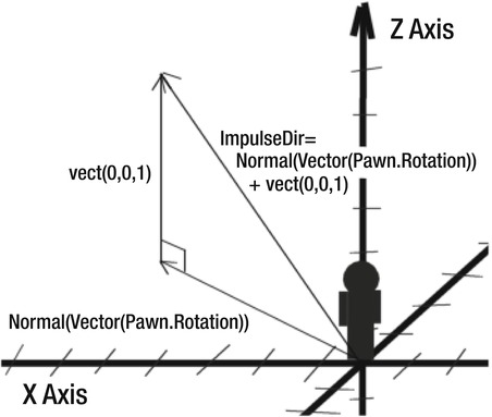
Figure 4–8. Calculating the Impulse Direction vector
NOTE: A vector is a quantity that has a magnitude and a direction and is used to represent such things as velocities, accelerations, and forces. Vectors can be added together to produce a resultant vector that is the net result of all the vectors combined. To get a more in depth discussion of vectors, please see Chapter 8 on 3D math.
The SetupZones() function sets up the SwipeZoneCallback() function to process player input. See Listing 4–6.
Listing 4–6. Settting up the Input Zones
function SetupZones()

{

    Super.SetupZones();


    // If we have a game class, configure the zones

    if (MPI != None && WorldInfo.GRI.GameClass != none)

    {

        LocalPlayer(Player).ViewportClient.GetViewportSize(ViewportSize);

        if (FreeLookZone != none)

        {

            FreeLookZone.OnProcessInputDelegate = SwipeZoneCallback;

        }

    }

}
PickDistance is set to a default value of 10000.
defaultproperties

{

    PickDistance = 10000;

}
The PickDistance is the maximum distance that an object can be from the player in order to be “picked” by the player.
We have now finished all the coding for this tutorial. The new ExampleCh41Game class we created specified that this game will use a custom player controller called ExampleCh41PC. It is this new player controller class that allows the user to select KActor objects and apply a force to them.
Next we need to configure the mobile game setup for the UDK for compiling our new code and for playing the actual game on the mobile previewer.
Configuring the New Game Type
You need to add in the mobile control zone definitions for our game type in the file Mobile-UDKGame.ini located by default at C:UDKUDK-2011-06UDKGameConfig.The following line defining the RequiredMobileInputConfigs for our game type ExampleCh41.ExampleCh41Game does that:
[ExampleCh41.ExampleCh41Game]

RequiredMobileInputConfigs=(GroupName="UberGroup",RequireZoneNames=("UberStickMoveZone",

"UberStickLookZone","UberLookZone"))
Now, open the UDKEngine.ini file located in the same directory. Under the UnrealEd.EditorEngine section heading, add in the line as below so that our new example will be added to the compilation list:
[UnrealEd.EditorEngine]

ModEditPackages= ExampleCh41
When you have finished editing the .ini files, bring up the Unreal Frontend and compile your new code.
Running the New Game Type
Start up the Unreal Editor and load in the level associated with this tutorial that you just created. Set your game type by selecting View ![]() World Properties from the main menu which brings up the world properties window. Under the Game Type category set the Default Game Type property to ExampleCh41Game.
World Properties from the main menu which brings up the world properties window. Under the Game Type category set the Default Game Type property to ExampleCh41Game.
Then start up the mobile game previewer by selecting the Play ![]() On Mobile Previewer from the main menu. (See Figure 4–9.)
On Mobile Previewer from the main menu. (See Figure 4–9.)

You can click on the sphere and cube to apply a force that will kick the object forward and upward. You may also need to use your mobile virtual joysticks to move the player so he can see the objects. Try moving around the arena and kicking the objects from various directions.
Hands-On Example: Creating a KAsset and applying a force to it
In this tutorial we will be creating a KAsset from a skeletal mesh asset and applying a force to this mesh. A skeletal mesh is different from a static mesh in that it is a mesh that contains moveable parts called bones.
Creating a KAsset
A good example of this is called SKM_Wire that is in the physics_assets.upk package that is downloadable from the official UDK website located at http://download.udk.com/tutorials/using-udk/3dbuzz_assets.zip
Unzip the file after you download it to a temporary directory.
- Create a new directory called “3dbuzz” under the
C:UDKUDK-2011-06UDKGameContent directory. - Copy the physics_assets.upk to this directory. This should put this new package into the Unreal Editor’s content manager. Start up the Editor and check to make sure the new assets appear under UDKGame Content 3dbuzz directory under Packages. You may have to right-click on the 3dbuzz directory and select “Fully Load” to refresh the Content Browser’s view.
- Next, right-click the SKM_Wire in the Content Browser. Select Create New Physics Asset from the context menu shown in Figure 4–10.
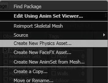
Figure 4–10. Creating a new Physics Asset
- A dialog box should show up asking you to enter the package and group where to place the new asset and the name of the new physics asset itself. Enter the information requested as shown in the Figure 4–11.
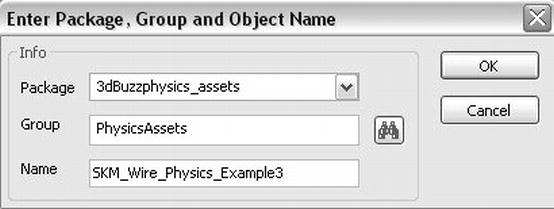
Figure 4–11. Naming a new Physics Asset
- Click the OK button. Next, another dialog box shows up requesting some setup information. Accept the default options, except change the Use Verts With entry to Any Weight as in Figure 4–12.
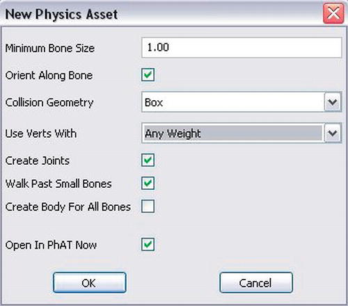
- Click the OK button and this new asset should be opened in Unreal Phat (Phat is short for Physics Assets). See Figure 4–13.
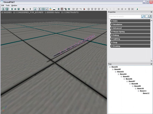
Figure 4–13. Unreal Physics Asset with our new Asset
Unreal Phat is used to set collision volumes and physics constraints for skeletal meshes. You should see a wire mesh that is divided by bounding boxes which enclose the separate bones that make up this wire. A bounding box is an invisible mesh that is used by the UDK Physics Engine to calculate physics collisions. Once you make sure that your wire looks similar to the above figure then close Unreal Phat window. Right-click on the new physics asset you created and select “Save” from the menu that pops up to save this asset and associated package.
Adding a KAsset to a Level
Our next step is to add a KAsset to the level. This KAsset will be the wire that we just created a physics asset for. We will also show you how exactly to put this in your level and how to set it up.
- Load in our level map from the previous tutorial.
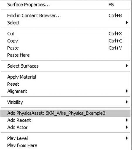
- Find and then select the new physics asset you have created. Right-click on the level where you want to put this new wire and select the Add Physics Asset option. See Figure 4–14.
- A wire mesh should be created in the level. Bring the wire up some so that you can get a better look at it using the transformation widget. See Figure 4–15.
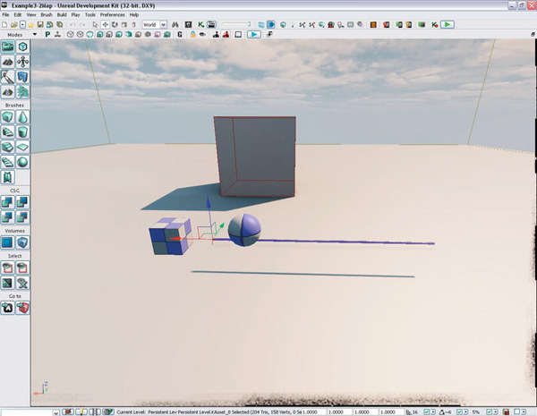
- Next, double-click on the wire to bring up its Properties window. See Figure 4–16.
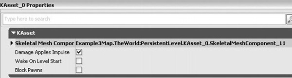
Figure 4–16. The KAsset Properties window
- Click on the Wake on Level Start checkbox to begin the physics simulation for this object when the level starts and then close the window.
- Now click on File Save As and save the level, for example, as Example4–2Map when the dialog box comes up.
Now that we have added the KAsset to our level, let’s turn to the code.
Creating the Unreal Script Code
It’s time now for you to create the code for this example. Create a new directory for this example as you did for the previous example at DevelopmentSrcExampleCh42Classes where you will place the code for this tutorial. Next you will define the game type and then the player controller.
Custom Game Type
The code for the new game type is almost the same as ExampleCh41. Although take note of the new class definition ExampleCh42Game as well as the new player controller that is derived from the PlayerController class. See Listing 4–7.
Listing 4–7. Game Type
class ExampleCh42Game  extends FrameworkGame;

event OnEngineHasLoaded()

{

    WorldInfo.Game.Broadcast(self," ExampleCh42Game  Type Active - Engine Has Loaded

!!!!");

}

function bool PreventDeath(Pawn KilledPawn, Controller Killer, class<DamageType>

DamageType, vector HitLocation)

{

    return true;

}

static event class<GameInfo> SetGameType(string MapName, string Options, string Portal)

{

    return super.SetGameType(MapName, Options, Portal);

}


defaultproperties

{


    PlayerControllerClass=class'ExampleCh42.ExampleCh42PC'


    DefaultPawnClass=class'UDKBase.SimplePawn'

    HUDType=class'UDKBase.UDKHUD'


    bRestartLevel=false

    bWaitingToStartMatch=true

    bDelayedStart=false

}
Custom Player Controller
Applying a force to a KAsset is a little different than for a KActor. For a KAsset you need to apply the force to the SkeletalMeshComponent of the KAsset object. Here we have specified the bone to apply the impulse to which is ‘Bone06’. This would be roughly the center of the wire since the wire is divided into 12 bones. You can verify this by bringing the wire up in UnrealPhat. Please refer back to Figure 4–12 where you can clearly see the 12 bones indicated by rectangular boxes.
For the player controller for this class the only things that have changed from the last tutorial are the class definition and the ApplyForceRigidBody function. See Listing 4–8.
Listing 4–8. Player controller class
class ExampleCh42PC  extends SimplePC;

var float PickDistance;

function ApplyForceRigidBody(Actor SelectedActor,

                              Vector ImpulseDir,

                              float ImpulseMag,

                              Vector HitLocation)

{

    if (SelectedActor.IsA('KActor'))

    {

        WorldInfo.Game.Broadcast(self,"*** Thrown object " @ SelectedActor @

                                               ", ImpulseDir = " @ ImpulseDir @

                                               ", ImpulseMag = " @ ImpulseMag @

                                               ", HitLocation = " @ HitLocation);

        KActor(SelectedActor).ApplyImpulse(ImpulseDir,ImpulseMag, HitLocation);

    }

    else


    if (SelectedActor.IsA('KAsset'))

    {

        WorldInfo.Game.Broadcast(self,"*** Thrown object " @ SelectedActor @

                                               ", ImpulseDir = " @ ImpulseDir @

                                               ", ImpulseMag = " @ ImpulseMag @

                                               ", HitLocation = " @ HitLocation);

        KAsset(SelectedActor).SkeletalMeshComponent.AddImpulse(ImpulseDir* ImpulseMag,

,'Bone06'),    }

    else

    {

        WorldInfo.Game.Broadcast(self,"!!!ERROR Selected Actor " @ SelectedActor @

                                              " is not a KActor or KAsset, you can not

apply an impulse to this object!!!");

    }

}

function Actor PickActor(Vector2D PickLocation, out Vector HitLocation, out TraceHitInfo

HitInfo)

{

    local Vector TouchOrigin, TouchDir;

    local Vector HitNormal;

    local Actor  PickedActor;
    local vector Extent;


    //Transform absolute screen coordinates to relative coordinates

    PickLocation.X = PickLocation.X / ViewportSize.X;

    PickLocation.Y = PickLocation.Y / ViewportSize.Y;


    //Transform to world coordinates to get pick ray

    LocalPlayer(Player).Deproject(PickLocation, TouchOrigin, TouchDir);


    //Perform trace to find touched actor

    Extent = vect(0,0,0);

    PickedActor = Trace(HitLocation,

                        HitNormal,

                        TouchOrigin + (TouchDir * PickDistance),

                        TouchOrigin,

                        True,

                        Extent,

                        HitInfo);


    //Return the touched actor for good measure

    return PickedActor;

}

function bool SwipeZoneCallback(MobileInputZone Zone,

                                float DeltaTime,

                                int Handle,

                                EZoneTouchEvent EventType,

                                Vector2D TouchLocation)

{

    local bool retval;


    local Actor PickedActor;

    local Vector HitLocation;

    local TraceHitInfo HitInfo;


    // Variables for physics

    local Vector ImpulseDir;

    local float ImpulseMag;


    retval = true;


    if (EventType == ZoneEvent_Touch)

    {

        // If screen touched then pick actor

        PickedActor = PickActor(TouchLocation,HitLocation,HitInfo);


        WorldInfo.Game.Broadcast(self,"PICKED ACTOR = "

                                       @ PickedActor @ ", HitLocation = "

                                       @ HitLocation @ ", Zone Touched = "

                                       @ Zone);


        // Set to roughly 45 degree angle

        ImpulseDir = Normal(Vector(Pawn.Rotation)) + vect(0,0,1);

        ImpulseMag = 500;


        ApplyForceRigidBody(PickedActor,ImpulseDir,ImpulseMag,HitLocation);


    }
    else

    if(EventType == ZoneEvent_Update)

    {

    }

    else

    if (EventType == ZoneEvent_UnTouch)

    {

    }

    return retval;

}

function SetupZones()

{

    Super.SetupZones();


    // If we have a game class, configure the zones

    if (MPI != None && WorldInfo.GRI.GameClass != none)

    {

        LocalPlayer(Player).ViewportClient.GetViewportSize(ViewportSize);

        if (FreeLookZone != none)

        {

            FreeLookZone.OnProcessInputDelegate = SwipeZoneCallback;

        }

    }

}

defaultproperties

{

    PickDistance = 10000;

}
Configuring the New Game Type
Now we need to set up the new code for compilation and setup the new game and map to run in the Mobile Previewer. Under your UDKGameConfig directory add or change entries in your Mobile-UDKGame.ini and UDKEngine.ini files to the following.
In your Mobile-UDKGame.ini file add mobile input controls for your new game.
[ExampleCh42.ExampleCh42Game]

RequiredMobileInputConfigs=(GroupName="UberGroup",RequireZoneNames=("UberStickMoveZone",

"UberStickLookZone","UberLookZone"))
In your UDKEngine.ini file, add in ExampleCh42 to the compilation list
[UnrealEd.EditorEngine]

ModEditPackages=ExampleCh42
Running the New Game Type
Bring up the Unreal Editor and load in the level with the wire. Select the View ![]() World Properties to bring up the world Properties window. Under the Game Type category set the Default Game Type to ExampleCh42Game.
World Properties to bring up the world Properties window. Under the Game Type category set the Default Game Type to ExampleCh42Game.
Run your Mobile Game on the previewer by selecting Play ![]() On Mobile Previewer from the Editor’s menu and click on the wire to apply a force. See Figure 4–17.
On Mobile Previewer from the Editor’s menu and click on the wire to apply a force. See Figure 4–17.
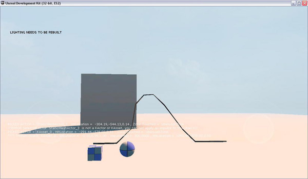
Figure 4–17. KActors and a KAsset
You should be able to kick around both the cube and sphere which are KActors and the wire which is a KAsset.
In conclusion, KActors and KAssets form the basis for objects providing realistic collisions. KActors are objects that are composed of static meshes and KAssets are objects that are composed of skeletal meshes. You can easily apply forces to both kinds of objects through Unreal Script and have the Unreal Physics Engine process them.
Physics Constraints
This section will discuss physics constraints. First an overview is given followed by a hands-on example where you tie several objects together and apply a force to see how those tied objects react.
Physics Constraints Overview
Physics constraints are objects that can be used to bind together different objects. Physics constraints are very flexible and have many options that can specify exactly how objects are to be tied together. With a physics constraint you can bind one actor to another or to the world itself by specifying None for that actor. If constraining a skeletal mesh you can specify which bone name to bind to.
For example, an arrow attached to a string that when fired from a bow will allow the user to retract the arrow and retrieve whatever the arrow has penetrated. The arrow would be a static mesh KActor and the string would be a skeletal mesh KAsset that are tied together via a physics constraint. The arrow would be tied to one end of the string which would be the bone at the end of the string mesh. When the arrow hits the target a dynamic constraint is generated to tie the arrow to the target which is then pulled back to the user of the bow.
Linear Constraints
Linear constraints can be hard. That is, when the two objects reach their linear limits, they stop suddenly. Linear constraints can also be soft in that instead of stopping suddenly they behave as if they are attached by a spring. Finally, linear constraints can also be set to break if enough force is applied to the constraint.
The following list provides some additional information for each type of linear constraint:
- Hard Linear Constraints—You can limit linear movement of constrained objects by setting
bLimitedto 1 for that axis and settingLimitSizeto the limits for that axis - Soft Linear Constraints— If
bLinearLimitSoftis set to true then the linear limits make the constraint behave like a spring using theLinearLimitStiffnessvalue to determine the extent of this behavior rather than hard limits where the object suddenly stops when it reaches this limit. TheLinearLimitDampingvalue would then control the damping. - Breakable Linear Constraints—You can also set if this constraint is breakable or not. If
bLinearBreakableis true then this constraint can break if the force exerted on it is greater than or equal to theLinearBreakThresholdvalue.
Angular Constraints
Angular Constraints can be hard, soft, and breakable similar to the linear constraints except these constraints refer to angles rather than linear distance. The following list describes the several types of angular constraints:
- Hard Angular Constraints— In terms of angular movement if you set
bSwingLimitedto true you can limit the constrained object’s angle to a cone. The values ofSwing1LimitAngleandSwing2LimitAngledefine the swing limited movements.If
bTwistLimitedis set to true then the twist between the two constrained bodies is limited. The value ofTwistLimitAnglewill then determine the limits of the twist angle. - Soft Angular Constraints— If
bSwingLimitSoftis set to true then the constraint will act like a spring instead of being a hard limit and the value ofSwingLimitStiffnesswill determine the behavior of this spring withSwingLimitDampingcontrolling the damping.If
bTwistLimitSoftis set to true then the constraint acts as a spring instead of a hard limit andTwistLimitStiffnesscontrols the spring stiffness withTwistLimitDampingcontrolling the damping. - Breakable Angular Constraints—If
bAngularBreakableis set to true then this constraint can be broken by twisting it apart when the force applied is greater than or equal toAngularBreakThreshold.
You can create physics constraints using the Unreal Editor and place them into the level or you can create them dynamically while the player is playing the game.
Predefined Constraints
There are already some pre-defined constraint types that set up the above values to make the constraint behave in a certain manner such as:
- Ball and Socket Constraint (RB_BSJointActor) which has its linear movement locked and its angular movements completely free.
- Hinge Constraint (RBHingeActor) which has its linear movement locked and can swing around like a door hinge.
- Prismatic Constraint (RBPrismaticActor) which has 2 out of 3 linear axes of movement locked and all of the angular movements locked. This allows it to behave similar to a sliding gate or door.
- Pulley Constraint (RB_PulleyJoinActor) which simulates a pulley where pulling down one object constrained by the pulley pulls up on the other object.
Dynamically Created Physics Constraints
You can also dynamically create physics constraints. The following is an example of creating a physics constraint using Unreal Script using the RB_ConstraintActorSpawnable class.
Var RB_ConstraintActorSpawnable  Constraint1;

Var Actor RopeStart,RopeSection2;


Pos = RopeSection2.Location;

Constraint = Spawn(class'RB_ConstraintActorSpawnable',,,Pos);

Constraint.InitConstraint(RopeStart, RopeSection2 , 'Bone12', 'Bone01'),
Now that you have an idea of how constraints work, let’s put them to work in a practical example.
Hands-On Example: Creating physics constraints with the Unreal Editor
In this example we will show you how to create physics constraints in the Unreal Editor. Physics constraints are what you use to tie objects together in various ways. Examples that use physics constraints include doors, sliding gates, punching bags and of course the wire we used in our previous tutorial. The wire was composed of smaller segments that were constrained together. In this example you will tie together a cube and a sphere to the ends of the wire you created in the previous example. You will then apply a force to parts of this combination and observe the reaction.
Adding New Objects to a Level
First we need to add in some new elements to our level from the KAsset example. We need to make copies of the cube, sphere, and the wire and put them together using physics constraints.
- Start the Unreal Editor and load in the level from the previous example that contains the sphere, cube, and wire.
- Right-click the sphere and select Copy from the context menu.
- Right-click on the place in the level where you want to place the sphere and select Paste.
You may have to move the new object so that it does not penetrate the ground using the transformation widget. Use the same procedure to copy and paste copies of the cube and the wire in the same general area.
Constraining Objects
Once you get all the objects copied and pasted you will need to constraint these together. To do this we will use a physics constraint called a ball and socket joint. The ball and socket joint constrains the objects linearly so that the constrained objects do not move in the X, Y, and Z directions. However, the ball and socket joint is not constrained in terms of its angular movement so it is free to rotate around the X, Y, and Z axes. You can also modify these properties if you want to after you create the new constraint. To create a new ball and socket constraint change the tab in the Unreal Editor from “Content Browser” to “Actor Classes”.
- Select RB_BSJointActor under the Physics category. See Figure 4–18.

- Then right-click on an empty area in your level and select Add RB_BSJoint Actor Here to add it to your level. See Figure 4–19.
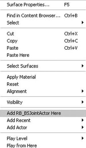
The constraint should appear in the level. See Figure 4–20.

Figure 4–20. Physics Constraint and Properties
There are two key properties under the RB_Constraint Actor category. The Constraint Actor 1 and Constraint Actor 2 properties are the actors to bind together with this physics constraint. Under the RB_Constraint Setup category, Constraint Bone 1 refers to the bone from the first actor (if any) to constrain and the Constraint Bone 2 refers to the bone from the second actor (if any) to constrain. Thus, you can constrain a static mesh (KActor) to a skeletal Mesh (KAsset) using one of the skeletal mesh’s bones. This is actually what we are going to do.
- First arrange a cube, one end of the wire, and the constraint as in the following. See Figure 4–21.
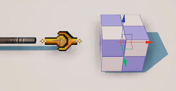
- Then move the wire, constraint and cube so that they are close together but not overlapping. The reason for this is if you overlap them too much the collision areas of both objects with overlap and the physics engine will try to fix this situation with attempting to push them apart resulting in weird behavior.
- Then double-click on the constraint to bring up its properties. Next you need to set the lock on the upper right hand side of the properties window so that you can select an actor in the viewport and keep the properties windows open and on top. See Figure 4–22.

Figure 4–22. Click on the Lock Icon to keep window open and on top
- After clicking the lock icon the graphic should change from an unlocked image to one that is locked. See Figure 4–23.

Figure 4–23. Properties window is now locked
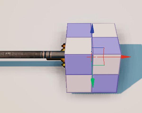
- Now you can easily click on the wire and set this as Constraint Actor 1. Click on the cube and set this as Constraint Actor 2. The Constraint Bone 1 will be either Bone01 or Bone12 depending on the wire’s orientation. After setting the bone you should see a line going from the constraint to the actual bone in the wire that it is now constrained to. If this bone is not at the end of the wire that is closest to the cube then you need to change the bone name to Bone01. See Figure 4–24.

Figure 4–24. Constraint binding a KAsset (Bone1 at End of Wire) with a Kactor (Cube)
- After properly setting the constraint properties you need to slide the end of the wire, constraint, and the cube closer together to make it look as if they are attached. You may need to turn off the grid snapping feature of the editor in order to get a good fit between the objects. Grid snapping is a feature that allows the user to move an object only in specified increments. For our example, uncheck the Grid Snapping checkbox (see Figure 4–25).

Figure 4–25. Turning Grid Snapping on/off
After placing the cube and the wire closer together it should look something like Figure 4–26.
- Next, you need to set up the constraints for the sphere and the other end of the wire using the same method as for the cube. The final result should look like Figure 4–27.

Figure 4–27. Sphere and Cube constrained to opposite ends of the Wire.
- Now save the level and exit the Unreal Editor.
Changing the Unreal Script
The next thing you need to do is increase the value of the force applied to an object when you click on it. Open the ExampleCh42PC.uc file in the ExampleCh42 directory and change the line in the function SwipeZoneCallback() to increase the impulse magnitude.
ImpulseMag = 500;
Now you are ready to run the game.
Running the new Game Type
Follow these steps to run the game and see what you’ve created:
- Bring up the Unreal Frontend and recompile your script code.
- Start up the Unreal Editor and load in the level for this exercise.
- Set the game type to ExampleCh42Game. Select View World Properties to bring up the World Properties window and set the Default Game Type to ExampleCh42Game under the Game Type category.
- Run the game on the mobile previewer by selecting Play On Mobile Previewer.
- Click on the sphere. You should see the sphere fly upward and forward while at the same time being attached to one end of the wire. As the sphere hits the ground it should also move the cube as well since the cube is attached to the sphere via the wire. See Figure 4–28.
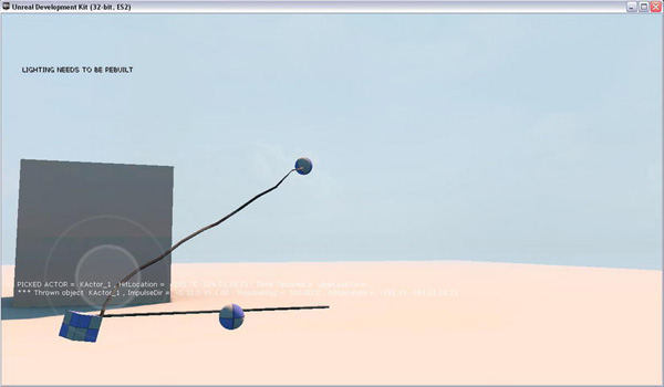
Figure 4–28. Using Physics Constraints to bind together a Sphere, Cube and a Wire
Collisions
This section covers collisions. First an overview of collisions in the UDK is given, followed by two hands-on examples. In the first example, you create a custom KActor collision object that is able to detect when another object collides with it. The second example shows how to make this custom object explode and disappear when hit hard enough.
Collision Overview
This section will explain how you would set up and handle collisions for a physics object. For our example, we will use a new class called RigidBodyCube that is derived from a KActor class.
class RigidBodyCube extends KActor

placeable;
The RigidBodyCollision() function is declared in the Actor class and will be overridden here. This function will process collisions for this object.
event RigidBodyCollision(PrimitiveComponent HitComponent,

                          PrimitiveComponent OtherComponent,

                          const out CollisionImpactData RigidCollisionData,

                          int ContactIndex)

{

    // Process Collision Here

}
This function is called under certain circumstances when a PrimitiveComponent that is owned by this class has
- bNotifyRigidBodyCollision = true
- ScriptRigidBodyCollisionThreshold is > 0
- Is involved in a physics collision where the relative velocities between the two objects exceed the ScriptRigidBodyCollisionThreshold value.
In the defaultproperties section, the 3D static mesh that represents this class is created through defining a StaticMeshComponent called RigidBodyCubeMesh and adding it to this class’s Component array.
defaultproperties

{

    Begin Object Class=StaticMeshComponent Name=RigidBodyCubeMesh

        StaticMesh=StaticMesh'EngineMeshes.Cube'


        CollideActors=true

        BlockActors=true

        BlockRigidBody=true


        bNotifyRigidBodyCollision=true

        ScriptRigidBodyCollisionThreshold=0.001

        RBChannel=RBCC_GameplayPhysics
        RBCollideWithChannels=(Default=true,

                                BlockingVolume=true,

                                GameplayPhysics=true,

                                EffectPhysics=true)

        End Object

    StaticMeshComponent=RigidBodyCubeMesh

    Components.Add(RigidBodyCubeMesh)

    CollisionComponent = RigidBodyCubeMesh


    bWakeOnLevelStart = true


    Physics = PHYS_RigidBody

    BlockRigidBody = true

    bBlockActors = true

    bCollideActors = true

}
The Component array holds items that are attached to this class object’s location and rotation. The actual 3D static mesh that is used to represent this class is defined in the StaticMesh variable that is set equal to a Cube. The StaticMeshComponent of the KActor is also set to the RigidBodyCubeMesh. The CollisionComponent which points to the collision mesh used for colliding this object against other objects also is set to the RigidBodyCubeMesh.
The following lists the key variables that must be set to produce rigid body collisions for this class and for components within this class:
- The
CollideActorsvariable must be set to true so that this object will be considered for collisions. - The
BlockActorsvariable should be set to True so the Player will be blocked from moving through this object. - The
BlockRigidBodyvariable must be set to True to have this object collide with other objects that use the Novodex physics engine. - The
bNotifyRigidBodyCollisionvariable must be set to true and theScriptRigidBodyCollisionThresholdvariable must be > 0 to have theRigidBodyCollision()function called for collision processing. - The variable
RBChannelshould be set toRBCC_GameplayPhysicswhich indicates what type of object this is with respect to a rigid body physics collision. TheRBCollideWithChannelsvariable indicates what other kinds of objects can collide with this one. - The variable bWakeOnLevelStart is set to true to indicate that this object’s physics simulation should begin when the level starts up.
- The Physics variable of this object is set to
PHYS_RigidBodyto indicate that Rigid Body physics simulation using the Novodex physics engine should be performed on this object. - The variable
BlockRigidBodyin the KActor class is set to true to indicate that objects of this class will collide with other Rigid Bodies. - The variable
bBlockActorsin the KActor class is set to true to indicate that objects of this class will block a player from moving through it. - The variable
bCollideActorsin the KActor class is set to true to indicate that objects of this class are enabled for collision detection.
Next, let’s see how the above variables are used in a real hands-on example.
Hands-on Example: Creating a Collision Object and Putting It in a Level
In this tutorial you will creating a new class RigidBodyCube that will be a KActor rigid body and that will be placeable in a level using the Unreal Editor. An object of the RigidBodyCube class will be able to tell when it is hit. When hit the function RigidBodyCollision() will be called and code can be added to handle the event.
Creating the Unreal Script
The first thing we need to do is create the code for RigidBodyCube object as well as the other classes, such as the game type, and player controller, and compile it. We need to do this in order to put this new class into the UDK system where the Unreal Editor will have access to it.
Create a new directory for your code at DevelopmentSrc ExampleCh43Classes under your UDK installation directory. Then, as previously, you will define the game type and create the player controller. Finally, you define the RigidBodyCube class.
Custom Game Type
First create the class that defines the type of game the player will be playing and put it in a new file ExampleCh43Game.uc. See Listing 4–9.
Listing 4–9. Game type
class ExampleCh43Game extends FrameworkGame;


event OnEngineHasLoaded()

{

    WorldInfo.Game.Broadcast(self," ExampleCh43Game Type Active - Engine Has Loaded

!!!!");

}


function bool PreventDeath(Pawn KilledPawn, Controller Killer, class<DamageType>

DamageType, vector HitLocation)

{

    return true;

}


static event class<GameInfo> SetGameType(string MapName, string Options, string Portal)

{

    return super.SetGameType(MapName, Options, Portal);
}


defaultproperties

{


  PlayerControllerClass=class'ExampleCh43.ExampleCh43PC'


    DefaultPawnClass=class'UDKBase.SimplePawn'

    HUDType=class'UDKBase.UDKHUD'


    bRestartLevel=false

    bWaitingToStartMatch=true

    bDelayedStart=false

}
Custom Player Controller
Next, you need to create the custom player controller. Create a new file called ExampleCh43PC.uc using the code in Listing 4–10.
Listing 4–10. Player controller
class ExampleCh43PC  extends SimplePC;


var float PickDistance;


function ApplyForceRigidBody(Actor SelectedActor, Vector ImpulseDir,float ImpulseMag,

Vector HitLocation)

{

    if (SelectedActor.IsA('KActor'))

    {

        WorldInfo.Game.Broadcast(self,"*** Thrown object " @ SelectedActor @

                                               ", ImpulseDir = " @ ImpulseDir @

                                               ", ImpulseMag = " @ ImpulseMag @

                                               ", HitLocation = " @ HitLocation);

        KActor(SelectedActor).ApplyImpulse(ImpulseDir,ImpulseMag, HitLocation);

    }

    else

    if (SelectedActor.IsA('KAsset'))

    {

        WorldInfo.Game.Broadcast(self,"*** Thrown object " @ SelectedActor @

                                               ", ImpulseDir = " @ ImpulseDir @

                                               ", ImpulseMag = " @ ImpulseMag @

                                               ", HitLocation = " @ HitLocation);

        KAsset(SelectedActor).SkeletalMeshComponent.AddImpulse(ImpulseDir* ImpulseMag,

,'Bone06'),

    }

    else

    {

        WorldInfo.Game.Broadcast(self,"!!!ERROR Selected Actor " @ SelectedActor @

                                              " is not a KActor or KAsset, you can not

apply an impulse to this object!!!");

    }

}
function Actor PickActor(Vector2D PickLocation, out Vector HitLocation, out TraceHitInfo

HitInfo)

{

    local Vector TouchOrigin, TouchDir;

    local Vector HitNormal;

    local Actor PickedActor;

    local vector Extent;


    //Transform absolute screen coordinates to relative coordinates


    PickLocation.X = PickLocation.X / ViewportSize.X;


    PickLocation.Y = PickLocation.Y / ViewportSize.Y;

       //Transform to world coordinates to get pick ray

    LocalPlayer(Player).Deproject(PickLocation, TouchOrigin, TouchDir);

        //Perform trace to find touched actor    Extent = vect(0,0,0);

    PickedActor = Trace(HitLocation,

                         HitNormal,

                         TouchOrigin + (TouchDir * PickDistance),

                         TouchOrigin,

                         True,

                         Extent,

                         HitInfo);


        //Return the touched actor for good measure

        return PickedActor;

}

function bool SwipeZoneCallback(MobileInputZone Zone,

                                 float DeltaTime,

                                 int Handle,

                                 EZoneTouchEvent EventType,

                                 Vector2D TouchLocation)

{

    local bool retval;


    local Actor PickedActor;

    local  Vector HitLocation;

    local TraceHitInfo HitInfo;


    // Variables for physics

    Local Vector ImpulseDir;

    Local float ImpulseMag;


    Local float KickAngle;


    // Constants defined in Object.uc

    // const Pi = 3.1415926535897932;

    // const RadToDeg = 57.295779513082321600;      // 180 / Pi

    // const DegToRad = 0.017453292519943296;       // Pi / 180

    // const UnrRotToRad = 0.00009587379924285;     // Pi / 32768

    // const RadToUnrRot = 10430.3783504704527;     // 32768 / Pi

    // const DegToUnrRot = 182.0444;

    // const UnrRotToDeg = 0.00549316540360483;


    retval = true;        if (EventType == ZoneEvent_Touch)

    {
        // If screen touched then pick actor

        PickedActor = PickActor(TouchLocation,HitLocation,HitInfo);


        WorldInfo.Game.Broadcast(self,"PICKED ACTOR = "

                                       @ PickedActor @ ", HitLocation = "

                                       @ HitLocation @ ", Zone Touched = "

                                       @ Zone);


        KickAngle = 15 * DegToRad;

        ImpulseDir = (Normal(Vector(Pawn.Rotation)) * cos(KickAngle)) + (vect(0,0,1) *

sin(KickAngle));


        ImpulseMag = 500;

        ApplyForceRigidBody(PickedActor,ImpulseDir,ImpulseMag,HitLocation);

    }

    else

    if(EventType == ZoneEvent_Update)

    {

    }

    else

    if (EventType == ZoneEvent_UnTouch)

    {

    }

    return retval;

}


function SetupZones()

{

    Super.SetupZones();


    // If we have a game class, configure the zones

    if (MPI != None && WorldInfo.GRI.GameClass != none)

    {

        LocalPlayer(Player).ViewportClient.GetViewportSize(ViewportSize);

                if (FreeLookZone != none)

        {

            FreeLookZone.OnProcessInputDelegate = SwipeZoneCallback;        }

    }

}


defaultproperties

{

    PickDistance = 10000;

}
Most of the code is the same as the previous example in Listing 4–8. However, there are some new elements.
KickAngle = 15 * DegToRad;
Kickangle is the angle that the force is applied to the object measured from the horizontal and is set to 15 degrees.
ImpulseDir is a vector that represents the direction of the force that will be applied to the object. The ImpulseDir is composed of two parts the forward vector component and the vertical vector component that when added together produces the final direction of the force. The forward component of the direction is calculated by multiplying the normalized vector representing the direction the player’s pawn is facing by the cosine of the KickAngle. The vertical component is calculated by multiplying the Z axis unit vector by the sine of the KickAngle.
NOTE: Basically, we figure out the horizontal and vertical components of the ImpulseDir vector on a 2D plane and then project them onto the 3D world by multiplying each component by horizontal and vertical 3D unit vectors. Please refer to Chapter 8 for more information on vectors, sine, cosine, etc as well as a detailed explanation of the mathematics involved in this example.
This gives the forward and vertical components a range of 0 to 1. If the KickAngle is 0 then the cosine of this angle is 1 and the sine of this angle is 0. This would make the direction all in the forward direction and none in the vertical direction as expected. If the KickAngle is 90 degrees or PI/2 then the cosine of the angle would be 0 and the sine of the angle would be 1. This would make the forward component 0 and would maximize the vertical direction.
ImpulseDir = (Normal(Vector(Pawn.Rotation)) * cos(KickAngle)) + (vect(0,0,1) *

sin(KickAngle));
The other code in Listing 4–10 was explained previously in the first Hands-on Example of this chapter.
The RigidBodyCube Class
The next class you will need to create is the RigidBodyCube class. Create a new file called RigidBodyCube.uc and enter the following code into it and then save the file. Declare the new RigidBodyCube class as follows. The placeable option at the end of the class indicates that this class is defined as placeable. That means that using the Unreal Editor you can select this class from the Actor Classes tab and right-click on the level to place an object of this type in the actual game level. The new RigidBodyCube class is declared as a subclass of KActor. See Listing 4–11.
Listing 4–11. RigidBodyCube class
class RigidBodyCube extends KActor

placeable;

event RigidBodyCollision(PrimitiveComponent HitComponent,

                          PrimitiveComponent OtherComponent,

                          const out CollisionImpactData RigidCollisionData,

                          int ContactIndex)

{

WorldInfo.Game.Broadcast(self,"RigidBodyCube COLLISION!!!! - " @ self @

                                  ", HitComponent =  " @ Hitcomponent @

                                  " Has Collided with " @ OtherComponent @

                                  " With Force " @

VSize(RigidCollisionData.TotalNormalForceVector));

}

defaultproperties

{
        Begin Object Class=StaticMeshComponent Name=RigidBodyCubeMesh

        StaticMesh=StaticMesh'EngineMeshes.Cube'


        CollideActors=true

        BlockActors=true

        BlockRigidBody=true


        bNotifyRigidBodyCollision=true

        ScriptRigidBodyCollisionThreshold=0.001

        RBChannel=RBCC_GameplayPhysics

        RBCollideWithChannels=(Default=true,

                                BlockingVolume=true,

                                GameplayPhysics=true,

                                EffectPhysics=true)

    End Object

    StaticMeshComponent=RigidBodyCubeMesh

    Components.Add(RigidBodyCubeMesh)


    CollisionComponent = RigidBodyCubeMesh

    bWakeOnLevelStart = true


    bEdShouldSnap = false


    Physics = PHYS_RigidBody

    BlockRigidBody = true

    bBlockActors = true

    bCollideActors = true

}
The variable bEdShouldSnap is set to false to indicate that this object by default should not use grid snapping while in the editor. The rest of the code in the default properties block was explained in the collision overview section that was presented before this example.
Game Type Setup
Now we need to set up our new game type and compile our new code. In your UDKGameConfig directory change Mobile-UDKGame.ini and UDKEngine.ini to compile our new code.
Mobile-UDKGame.ini

[ExampleCh43.ExampleCh43Game]

RequiredMobileInputConfigs=(GroupName="UberGroup",RequireZoneNames=("UberStickMoveZone",

"UberStickLookZone","UberLookZone"))

UDKEngine.ini

[UnrealEd.EditorEngine]

ModEditPackages= ExampleCh43
Now bring up the Unreal Frontend and compile the code.
Setting up the Level
The next thing to do is to bring up the Unreal Editor so you can set up the level.
- First of all you need to load in your level from that last example and save it as a different map for this exercise.
- Go to the Actor Classes tab and under the Physics Kactor category and select the new
RigidBodyCubeclass you just created. See Figure 4–29.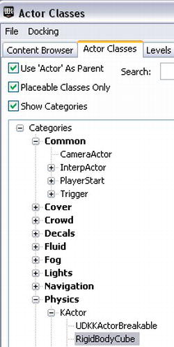
Figure 4–29. Selecting your new RigidBodyCube class from the Actor Classes Browser
- Right-click on an empty area in the level and select Add RigidBodyCube Here to add the object to your level. Double-click on the object to bring up its properties. See Figure 4–30.

- Change the Draw Scale property under the Display category to .20 and close out the properties window.
- Next you need to create a wall of blocks using this new class in the center of the arena. To help you along, selecting a block and then holding down the Alt key while dragging the transformation widget will allow you to simultaneously create a new copy of this object and drag that copy of the object using the transformation widget. Holding down the Ctrl key and clicking on multiple objects will allow you to select multiple objects for movement or copying using the Alt key technique. Also, make copies of the Spheres and place them around this wall of blocks, as in Figure 4–31.
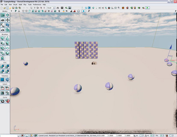
Figure 4–31. A wall made of our custom class RigidBodyCube
Running the Game Type
Finally, we are ready to try out our game. Change the level’s default game type to ExampleCh43Game and start the game up on the mobile previewer.
Try moving around the wall and kicking balls into it. When the ball hits the wall a message should appear stating that there was a RigidBodyCube collision. See Figure 4–32.

Figure 4–32. Ball hitting a block made of our new class RigidBodyCube
Hands-On Example: Making an exploding wall of blocks
This tutorial will build upon the last tutorial. Now what we need to do is take that wall of blocks and make them explode when you hit them with another object hard enough. In order to do this we need to change the code in the RigidBodyCube class.
Just under the class declaration add in the following variables. The ExplosionTemplate refers to the particle system that will be used for the explosion of a RigidBodyCube. You can search for particle systems in the Content Browser by checking the box under the Object Type ![]() Favorites heading and selecting “Mobile Game” under Packages. The Explosion variable holds a reference to a new emitter that is created using the
Favorites heading and selecting “Mobile Game” under Packages. The Explosion variable holds a reference to a new emitter that is created using the SpawnEmitter() function.
Var ParticleSystem ExplosionTemplate;

Var ParticleSystemComponent Explosion;
For this example, we have decided to “destroy” the block by moving it out of the player’s view and turning off Rigid Body physics for this object to save processing resources. This way we can easily add in more information later if needed such as the time this block was destroyed, what object destroyed it, and so on. The OutOfViewLocation variable holds the location in the world where destroyed blocks are moved to.
Var vector OutOfViewLocation;
The MinimumForceToExplode variable is the minimum force it would take to destroy a RigidBodyCube class object. bDestroyed is set to true if the RigidBodyCube is destroyed.
In the defaultproperties section add in the default values of the following variables
MinimumForceToExplode = 370;

bDestroyed = false

OutOfViewLocation = (X = 0, Y = 0, Z = -5000)

ExplosionTemplate = ParticleSystem'Castle_Assets.FX.P_FX_Fire_SubUV_01'
For the ExplosionTemplate default value you can actually view this system from within Unreal Cascade. Search for particle systems using the search term “fx_fire” in the “UDKGame” package and you should see 1 particle system asset. Double-click on this asset to bring it up in Unreal Cascade. See Figure 4–33
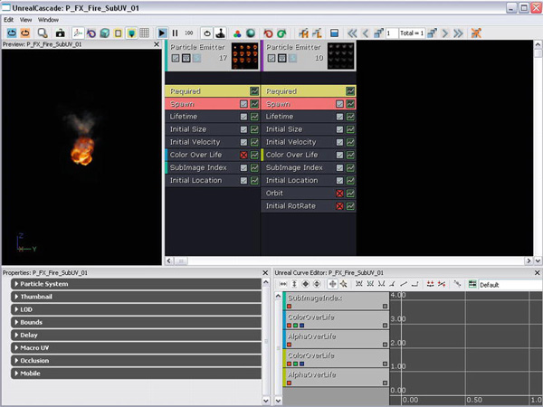
Figure 4–33. Our particle system used for explosions viewed in Unreal Cascade
You also need to change the RigidBodyCollision() function to the new function that follows. What this function does is first test to see if collision force between this object and the object that it collided into is equal to or greater than the minimum force needed to destroy this object. If it is then the object is destroyed. First a new explosion is created using a particle emitter that is spawned from a pool of particle emitters. Next, this object is moved to a location out of the player’s view, its physics state is set to none and its destroyed variable is set to true.
event RigidBodyCollision(PrimitiveComponent HitComponent,

                              PrimitiveComponent OtherComponent,

                              const out CollisionImpactData RigidCollisionData,

                              int ContactIndex)

{

    local vector ExplosionLocation;

    local float CollisionForce;


    WorldInfo.Game.Broadcast(self,"RigidBodyCube COLLISION!!!! - " @ self @

                                      ", HitComponent =  " @ Hitcomponent @

                                      " Has Collided with " @ OtherComponent @

                                      " With FOrce " @

VSize(RigidCollisionData.TotalNormalForceVector));


    CollisionForce = VSize(RigidCollisionData.TotalNormalForceVector);


    if (CollisionForce >= MinimumForceToExplode)

    {

        // Spawn Explosion Emitter

        ExplosionLocation = HitComponent.Bounds.Origin;

        Explosion = WorldInfo.MyEmitterPool.SpawnEmitter(ExplosionTemplate, ExplosionLocation);


        // Object has been Destroyed

        bDestroyed = true;


        // Move Rigid Body out of view

        HitComponent.SetRBPosition(OutOfViewLocation);

        SetPhysics(Phys_None);

    }

}
Recompile this code and launch the game. Kick some objects into the wall. See Figure 4–34.
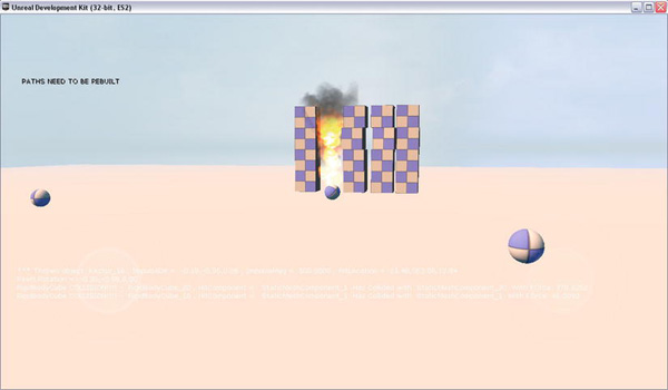
Figure 4–34. Kicking objects into wall formed by exploding RigidBodyCubes
Summary
In this chapter we covered the UDK physics system. We discussed collision meshes and how you can create your own through a 3d modeling program like Blender. We showed you how to create both KActors from static meshes and KAssets from skeletal meshes and how to apply forces to each type of object. Then we showed you how to use physics constraints to tie together KActors and KAssets so that a force applied to one of these objects will affect all of them. Next we demonstrated how to create a new class that was a placeable rigid body that is able to react to collisions. Building on that example we added code to make that new class explode when it collides with another object.