Chapter 8
3D Math Review
In this chapter we will review some basic 3D math concepts needed to fully understand the hands-on examples presented in the other chapters, including the frameworks that follow.
Understanding 3D math is needed for such things as positioning objects such as a camera in a 3D world, applying forces to objects, finding distances in between two objects, and finding if a cover node protects an actor hiding behind it from enemy fire. In general anything that deals with positioning an object, motion (which is nothing more than positioning an object in different locations at certain time intervals), or with measuring angles in a 3D world will require some knowledge of 3D math.
In this chapter you will learn about:
- Vector addition
- Vector multiplication
- Dot products
- Cross products
- Cover nodes that protect an actor from the enemy.
- Third-person camera positioning
- Deriving the direction vector for kicking objects at an arbitrary angle
Vectors
Vectors are essential to understanding 3D math. Vectors are quantities that have a magnitude and a direction. Vectors can represent quantities like forces that are applied to objects or represent the location of objects in the game world. Vectors can also represent location, velocity, or acceleration of objects in the game world.
Scalars, by contrast, are quantities that just have magnitude, like a speed 55 miles per hour, for example. A velocity vector would have both magnitude and direction, such as 55 miles per hour in a northwest direction.
Direction with respect to vectors is indicated by an arrow. Magnitude can be shown graphically by the length of this arrow.
Some properties of vectors are that they:
- Can be added together to produce a resultant vector that represents the net direction and magnitude of the vectors that are added.
- Can be multiplied by a scalar to change the magnitude of a vector but not the direction.
- Are used in dot products and cross products to find the angle between two vectors and to find a vector that is perpendicular to a pair of vectors.
You can visualize vectors as arrows that indicate direction and that have a length or magnitude like in Figure 8–1. This represents vectors on a 2D plane.
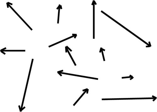
Figure 8–1. Vectors represented as arrows with magnitude and direction on a 2D plane
To visualize vectors within the Unreal 3D game world a better picture would be like in Figure 8–2.
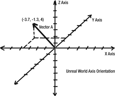
Figure 8–2. A vector in the 3D Unreal world coordinate system
In the Unreal world the X and Y axes represent the ground plane and the Z axis points upward toward the sky.As you can see from Figure 8–2 a vector is defined by two or three numbers in the form (X, Y, Z) depending if the vector is a 2D vector or a 3D vector.
The X, Y, and Z values represent the location of the head of the vector's arrow on the X, Y, and Z axes. For example, the Vector A in Figure 8–2 would be defined as –3.7 units on the X axis, -1.3 units on the Y axis, and 4 units on the Z axis. Based on these values we know the direction the vector is pointing. From these values we can also find the magnitude of this vector.
Vector Magnitude
The standard formula for finding the length or magnitude of a vector is as shown in Figure 8–3.
Figure 8–3. Finding the length of a vector
The above formula states that the length of vector A is the square root of the sum of the squares of each component of vector A.The components of A being the X, Y, and Z values of the vector which are (Ax, Ay, Az). The ||A|| notation indicates the absolute value of A, which means the result is always a positive number.
Using Vector A in Figure 8–2 as an example, Ax would be –3.7, Ay would be -1.3, and Az would be 4. Each of these terms would be squared and then added together. Then the square root would be taken from the sum, and the result would be the magnitude of Vector A.
MagA = SquareRoot((-3.7 * -3.7) + (-1.3 * -1.3) + (4 * 4))
MagA = SquareRoot(13.69 + 1.69 + 16)
MagA = SquareRoot(31.38)
MagA = 5.60
You can do the above in an UnrealScript class function as:
local vector VectorA;

local float Length;

VectorA = vect(-3.7, -1.3, 4);
In UnrealScript there is a built in function to perform this operation which is the VSize() function. So in order to get the length of Vector A, you would just send Vector A as in input parameter like this:
Length = VSize(VectorA);
The Length variable would now contain the magnitude of Vector A.
Rotator to Vector Conversion
An Actor's rotation in the UDK game world is defined by a rotator which is a structure defined in the Object class.
struct immutable Rotator

{

    var() int Pitch, Yaw, Roll;

};
The pitch, yaw, and roll define an object's rotation around the X, Z, and Y axes.
You use the SetRotation() function to change the rotation of the Actor. The variable Rotation in the Actor class holds the object's rotation values in a Rotator structure.
For example to set an Actor to a state where it is not rotated you would use the following code in that Actor's class:
function ResetRotation()

{

    local Rotator TempRot;


    TempRot.pitch = 0;

    TempRot.yaw = 0;

    TempRot.Roll = 0;

    SetRotation(TempRot);

}
Since we are using the UDK, rotations are handled by the UDK graphics engine and we don't have to do any more work besides setting the rotation using SetRotation(). Without the UDK, we would need to rotate each object using matrix multiplication to get the desired rotation in the X, Y, and Z axes.
NOTE: If you are interested in the non UDK method of using matrices to transform and rotate objects then check out 3D Computer Graphics, Third Edition, by Alan Watt.
In UnrealScript there is an easy way to convert the rotation of an object to a vector value that points in the direction the front of the object is facing. For example, to get a vector that points in the direction the player's pawn is facing you would do the following:
PawnFrontVector = Vector(Pawn.Rotation);
You would use this in your player controller class.
Normalizing Vectors
Normalized vectors are vectors of length 1 and are also called unit vectors. The importance of normalized vectors is that you can isolate the direction of the vector from the magnitude. That is, once you find the unit vector that indicates direction, then you can make this vector have any magnitude you want by multiplying the desired magnitude by the unit vector. Figure 8–4 shows the formula used for normalizing a vector.
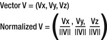
Figure 8–4. Calculating Normal Vectors
You normalize a vector by dividing each vector component by the magnitude of the original vector.
In UnrealScript there is a built in function called Normal() to perform this calculation. For example, the following would normalize vector V and return the new vector.
NormalizedV = Normal(V);
Vector Addition
Two vectors can be added by adding each of the components of the vectors. For example, two vectors A and B can be added together by adding the X, Y, and Z components of each vector.
ResultantVector = (Ax + Bx, Ay + By, Az + Bz);
For example, vector A is (1,0,0) which is a normal vector that points along the X axis, and vector B is (0,0,1) which is a normal vector that points upward along the Z axis. The resultant vector would be:
ResultantVector = (1 + 0, 0 + 0, 0 + 1)
ResultantVector = (1,0,1)
You can also add vectors graphically. However, this is not recommended as it gets complex quickly when dealing with many vectors.
Graphically, adding a group of vectors would look as in Figure 8–5.
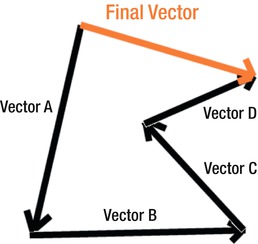
Figure 8–5. Adding Vectors
In order to add vectors together graphically you need to put them together head to tail. The resultant vector is the vector from the tail of the beginning vector to the head of the ending vector. Figure 8–5 illustrates how Vectors A, B, C, and D can be added together to get a final vector that is the net result of all the vectors combined.
It is much easier to add multiple vectors numerically. For example to add four vectors:
Vector A = (1,0,0)
Vector B = (0,0,1)
Vector C = (0,1,0)
Vector D = (1,1,1)
ResultantVector = (2,2,2)
In UnrealScript, you don't need to add the components but just add the vectors themselves as follows:
var vector VectorA,VectorB,VectorC,VectorD;

var vector ResultantVector;

VectorA = vect(1,0,0);

VectorB = vect(0,0,1);

VectorC = vect(0,1,0);

VectorD = vect(1,1,1);

ResultantVector = VectorA + VectorB + VectorC + VectorD;
Scalar Multiplication
A scalar value is a quantity that has only a magnitude and no direction, such as a number representing things like the speed of an object. A vector can be multiplied by a scalar value by multiplying each vector component by the scalar.
For example, assume we have a unit vector B that is pointing along the x axis:
Vector B = (1,0,0)
We want to multiply this vector by scalar S which is 10. The resulting vector would be:
Resultant Vector = (1 * 10, 0 * 10, 0 * 10)
Resultant Vector = (10,0,0)
A unit vector can be multiplied by a scalar so that the resulting vector is of length scalar. See Figure 8–6.

Figure 8–6. Unit vector being scaled by a scalar
The resulting vector is the same direction as the unit vector but the length has been changed to the value of S.
An example of where this would be useful is when you want to apply a certain amount of force to an object in a certain direction. You would make the direction vector into a unit vector of length 1, and then you would multiply the unit vector times the amount of force you want to apply to the object. The resulting vector is the force vector that includes the direction and amount of force to apply to the object. In the above example, Vector B would represent the unit direction vector and the scalar value S which is 10 would represent the force. The resultant vector represents a force of 10 along the x axis.
You can also change the direction of a vector to point in the opposite direction by multiplying it by a scalar value of –1. See Figure 8–7.
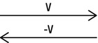
Figure 8–7. Changing the direction of a vector
For example, you want to find a vector that represents the back side of the player's pawn. In order to do this you would multiply the vector representing the front of the player's pawn by –1 to get a vector that points in the opposite direction.
Unit Circle
In order to understand fundamental trigonometry functions like sine and cosine you need to understand the unit circle. See Figure 8–8.

Figure 8–8. The Unit Circle with an angle Theta shown
A unit circle is a circle of radius of length 1 and is used to illustrate how cosine and sine values are derived. Understanding how cosine and sine values are derived from the unit circle is important since cosine and sine functions are involved in so many key things like vectors, dot products, and trigonometric identities that are needed to program games in a 3D world. The x axis of the unit circle defines cosine values which range from –1 to 1. The y axis defines sine values which also range from –1 to 1. An angle that is defined by ![]() (theta) can range from 0 to 360 degrees.
(theta) can range from 0 to 360 degrees.
NOTE: Rotation angles in the UDK are measured in Unreal Rotation Units. For example, the value of PI is 32768 Unreal Rotation Units. The value UnrRotToRad is defined in the Object.uc file and is used to convert Unreal Rotation Units to Radians.
Sine and cosine values are determined by the angle's intersection with the unit circle. For example, at 0 degrees the cosine value is 1 and the sine value is 0. At 90 degrees the cosine value is 0 and the sine value is 1. At 180 degrees the cosine value is –1 and the sine value is 0.
Right Triangle
The right triangle is important because it is used in several important trigonometric identities. See Figure 8–9.
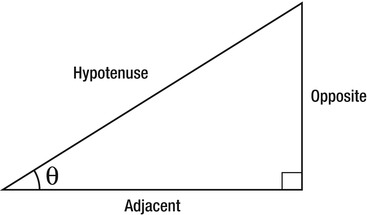
Figure 8–9. The right triangle
Key trigonometric identities are:
- Sin(
 ) = Opposite/Hypotenuse
 - Cos() = Adjacent/Hypotenuse
And
- Hypotenuse * Sin() = Opposite
- Hypotenuse * Cos() = Adjacent
The above identities are useful when trying to break a vector into its components. For example, imagine you kick an object that has a velocity vector that is 20 ft/s and makes an angle with the ground of 45 degrees. Let's assume you want to find the horizontal speed of the ball along the ground. The velocity vector can be considered the hypotenuse of a right triangle and the ground would be the adjacent side of the triangle:
Adjacent = Hypotenuse * cos(45)
VelocityGround = VelocityTotal * cos(45)
VelocityGround = 20 * cos(45) = 14.14
Dot Product
Imagine two vectors with an angle theta between them as in Figure 8–10.
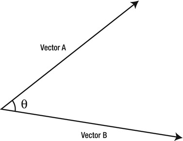
Figure 8–10. Two vectors with an angle theta
The definition of the dot product is given in Figure 8–11.
Figure 8–11. Dot Product definition
The dot product of two vectors is equal to the magnitude of vector A multiplied by the magnitude of vector B multiplied by the cosine of the angle between the two vectors.
To find the angle between the two vectors from the dot product you would use the formula in Figure 8–12.
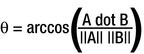
Figure 8–12. Finding an angle from the dot product of two vectors
The angle between objects in the 3D game world can be an important factor. One example is displaying information about important game objects only when they are in the view of the player. To do this you would only display information onscreen when these objects are within a certain angle with respect to the front of the player's pawn. One vector would be the one from the player to the object you are testing. The other vector would be the one pointing outward from the front of the player's pawn. You can then find the angle between these vectors using the equation in Figure 8–12. If the angle is within a certain range then you can display information about this object on screen.
In UnrealScript there is a built in dot function to perform the dot product between two vectors. For example, the following code finds the angle in degrees between two vectors assuming the two vectors have already been normalized.
AngleDegrees = acos(SlotNormal Dot DirectionToThreat) * RadToDeg;
A dot product can also be used to project a vector onto a unit vector as shown in Figure 8–13.
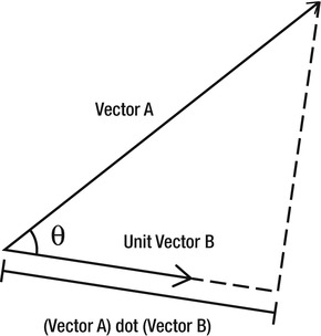
Figure 8–13. Dot product projection onto a unit vector
Note in the figure that using the dot product to project an arbitrary vector on a unit vector is basically another way of finding out the value of the Adjacent side of a right triangle. The Adjacent side of the triangle would be the one with the unit vector.
Cross Product
The cross product between two vectors generates a vector that is perpendicular to both vectors. See Figure 8–14.
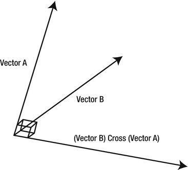
Figure 8–14. Cross Product
The cross product comes in handy when trying to find a vector to the left and right side of an Actor. For example, an enemy bot is hiding in cover and you want it to move sideways out of cover and fire at the player and then move back into cover. In order to do this you will need to find a vector that is perpendicular to both the bot's pawn front vector and the game world's up vector which would be the same as the positive Z axis. To do this you would take the cross product of these two vectors.
In UnrealScript there is a built in cross operator that calculates the cross product of two vectors. For example, the code below generates a perpendicular vector to the two input vectors using the cross operator.
RightVec = FrontVec cross vect(0,0,1);
Cover Nodes
A good applied example that uses vectors, angles, dot products, and trigonometric functions like sine and cosine is an example that involves creating cover nodes.In this section we will give an overview of cover nodes and a hands-on example that demonstrates their use in the Unreal world.
Cover Node Overview
A cover node is an area designated by the user that can provide protection or cover to a player or a computer-controlled bot from enemy fire. The cover node is implemented in the UDK in the class CoverLink. See Figure 8–15.

Figure 8–15. The UDK Cover Link (green and black image on the right) and Cover Slot (red block)
The cover node in the UDK consists of the actual node which is represented by a circular image with a picture of a man in the center and one or more cover slots. The cover slots are represented by a red block with an arrow pointing outward representing the cover slot's normal or perpendicular vector. For the examples in this book we assume a cover node has only 1 cover slot. Multiple cover slots per cover node are supported by the UDK; however, for simplicity we assume only 1 cover slot per cover node.
The general idea is that the cover slot be placed against an object that will serve as the cover with the cover slot's normal vector pointing toward the cover object. See Figure 8–16.

Figure 8–16. New Custom Cover Node System
In Figure 8–16 we have the cover node and a cover slot. The cover slot is placed against an object that will serve as cover from enemy fire. The cover slot's normal vector is oriented so that it faces the cover. The threat angle on the figure is the angle between the cover slot normal vector and the vector that goes from the cover node slot to the threat.
In addition, we have something new not in the default CoverLink class in the UDK base code. The cover protection angle is a new value that we have added to the new cover node class CoverLinkEx. This new class that is derived from the CoverLink class will be created in the hands-on example that follows this section. The cover protection angle is a value specified by the user which defaults to 45 degrees and measures from the cover slot normal to both the right and left sides of the normal.
A threat is covered if it is in the area between the two vectors that represent the cover protection angle. That is, the threat angle is less than the cover protection angle.
Hands-on Example: Cover Nodes
In this example we will be creating the new cover node class mentioned previously and showing it off in a demo where multiple bots take cover from the player who is considered by the bots to be the threat to take cover from. First we will create the new game type for this demo. Then, we will create the player controller, the bot's controller, the bot's pawn, and then the new cover node class. We will need to compile the code first so that the new cover node class is put into the UDK system before we start creating our new level that uses this new cover node class.
Creating the Game Type
We need to create a new directory under our source directory located at:
C:UDKUDK-2011-06DevelopmentSrc
for the June 2011 version of the UDK. If you are using a different version of the UDK then the above default directory will be different. Under the above directory create the folder ExampleCh8.Under that directory create the Classes directory. You will be putting all your source code for this hands-on example in this Classes directory.
The new game type that you will need to create is in Listing 8–1.
Listing 8–1. Game Type
class ExampleCh8Game extends FrameworkGame;


event OnEngineHasLoaded()

{

    WorldInfo.Game.Broadcast(self,"ExampleCh8Game Type Active - Engine Has Loaded !!!!");

}


function bool PreventDeath(Pawn KilledPawn, Controller Killer, class<DamageType> DamageType, vector HitLocation)

{

    return true;

}

static event class<GameInfo> SetGameType(string MapName, string Options, string Portal)

{

    return super.SetGameType(MapName, Options, Portal);

}

defaultproperties

{

    PlayerControllerClass=class'ExampleCh8.ExampleCh8PC'

    DefaultPawnClass=class'JazzPawnDamage'

    HUDType=class'UDKBase.UDKHUD'


    bRestartLevel=false

    bWaitingToStartMatch=true

    bDelayedStart=false

}
The PlayerControllerClass variable points to our new custom player controller for this example.
Creating the Player Controller
Next, you will need to create the new player controller class shown in Listing 8–2. This code should be familiar from earlier chapters. The important changes are set in bold.
Listing 8–2. Player Controller
class ExampleCh8PC extends SimplePC;


var Controller FollowBot;

Var Pawn FollowPawn;

var bool BotSpawned;

var Actor BotTarget;

var float PickDistance;


function Actor PickActor(Vector2D PickLocation, out Vector HitLocation, out TraceHitInfo HitInfo)

{

    local Vector TouchOrigin, TouchDir;

    local Vector HitNormal;

    local Actor  PickedActor;

    local vector Extent;


    //Transform absolute screen coordinates to relative coordinates

    PickLocation.X = PickLocation.X / ViewportSize.X;

    PickLocation.Y = PickLocation.Y / ViewportSize.Y;


    //Transform to world coordinates to get pick ray

    LocalPlayer(Player).Deproject(PickLocation, TouchOrigin, TouchDir);


    //Perform trace to find touched actor

    Extent = vect(0,0,0);

    PickedActor = Trace(HitLocation,

                        HitNormal,

                        TouchOrigin + (TouchDir * PickDistance),

                        TouchOrigin,

                        True,

                        Extent,

                        HitInfo);

    //Return the touched actor for good measure

    return PickedActor;

}

function SpawnBot(Vector SpawnLocation, optional Vector Offset)

{

    SpawnLocation = SpawnLocation + Offset;

    FollowBot = Spawn(class'BotCoverController',,,SpawnLocation);

    FollowPawn = Spawn(class'BotCoverPawn',,,SpawnLocation);

    FollowBot.Possess(FollowPawn,false);

    BotCoverController(FollowBot).BotThreat = Pawn;

    BotCoverpawn(FollowPawn).AddDefaultInventory();

    BotCoverPawn(Followpawn).InitialLocation = SpawnLocation;

    FollowPawn.SetPhysics(PHYS_Falling);

}

function bool SwipeZoneCallback(MobileInputZone Zone,

                                float DeltaTime,

                                int Handle,

                                EZoneTouchEvent EventType,

                                Vector2D TouchLocation)

{

    local bool retval;

    retval = true;

    if (EventType == ZoneEvent_Touch)

    {
        WorldInfo.Game.Broadcast(self,"You touched the screen at = " @

                                       TouchLocation.x @ " , " @ TouchLocation.y @

                                       ", Zone Touched = " @ Zone);

        // Start Firing pawn's weapon

        StartFire(0);

    }

    else

    if(EventType == ZoneEvent_Update)

    {

    }

    else

    if (EventType == ZoneEvent_UnTouch)

    {

        // Stop Firing Pawn's weapon

        StopFire(0);

    }

    return retval;

}

function SetupZones()

{

    Super.SetupZones();

    // If we have a game class, configure the zones

    if (MPI != None && WorldInfo.GRI.GameClass != none)

    {

        LocalPlayer(Player).ViewportClient.GetViewportSize(ViewportSize);

        if (FreeLookZone != none)

        {

            FreeLookZone.OnProcessInputDelegate = SwipeZoneCallback;

        }

    }

}

function PlayerTick(float DeltaTime)

{

    Super.PlayerTick(DeltaTime);

    if (!BotSpawned)

    {

        SpawnBot(Pawn.Location,vect(0,0,500));

        SpawnBot(Pawn.Location,vect(0,0,1000));

        SpawnBot(Pawn.Location,vect(0,0,1500));

        SpawnBot(Pawn.Location,vect(0,0,2000));

        SpawnBot(Pawn.Location,vect(0,0,2500));

        BotSpawned = true;

        JazzPawnDamage(Pawn).InitialLocation = Pawn.Location;

    }

}

defaultproperties

{

    BotSpawned=false

    PickDistance = 10000

}
Again, most of this code should look familiar to you from previous chapters. The key changes are in the SpawnBot() function where the bot's controller has been changed to the BotCoverController class and the bot's pawn has been changed to the BotCoverPawn class.The SpawnBot() function has also been modified to accept an offset vector that is added to SpawnLocation. The PlayerTick() function has been modified to create five bots that will be controlled by the new BotCoverController class using the new SpawnBot() function.
Creating the Bot's Pawn
Next, you need to create the pawn class for the bot. See Listing 8–3. You will recognize most of this code from previous examples. The line with the important change is set in bold.
Listing 8–3. Bot Pawn
class BotCoverPawn extends SimplePawn;


var Inventory MainGun;

var SoundCue JazzHitSound;

var vector InitialLocation;


event TakeDamage(int Damage, Controller InstigatedBy, vector HitLocation, vector Momentum, class<DamageType> DamageType, optional TraceHitInfo HitInfo, optional Actor DamageCauser)

{

    PlaySound(JazzHitSound);

    Health = Health - Damage;

    WorldInfo.Game.Broadcast(self,self @ " Has Taken Damage IN TAKEDAMAGE, HEALTH = " @ Health);


    if (Health <= 0)

    {

        SetLocation(InitialLocation);

        SetPhysics(PHYS_Falling);

        Health = 100;

    }

}

function AddGunToSocket(Name SocketName)

{

    local Vector SocketLocation;

    local Rotator SocketRotation;

    if (Mesh != None)

    {

        if (Mesh.GetSocketByName(SocketName) != None)

        {

            Mesh.GetSocketWorldLocationAndRotation(SocketName, SocketLocation, SocketRotation);

            MainGun.SetRotation(SocketRotation);

            MainGun.SetBase(Self,, Mesh, SocketName);

        }

        else

        {

            WorldInfo.Game.Broadcast(self,"!!!!!!SOCKET NAME NOT FOUND!!!!!");

        }
    }

    else

    {

        WorldInfo.Game.Broadcast(self,"!!!!!!MESH NOT FOUND!!!!!");

    }

}

function AddDefaultInventory()

{

    MainGun = InvManager.CreateInventory(class'JazzWeapon2Damage'),

    MainGun.SetHidden(false);

    AddGunToSocket('Weapon_R'),

    Weapon(MainGun).FireOffset = vect(0,13,-70);

}

defaultproperties

{

    // Jazz Mesh Object

    Begin Object Class=SkeletalMeshComponent Name=JazzMesh

        SkeletalMesh=SkeletalMesh'KismetGame_Assets.Anims.SK_Jazz'

        AnimSets(0)=AnimSet'KismetGame_Assets.Anims.SK_Jazz_Anims'

        AnimTreeTemplate=AnimTree'KismetGame_Assets.Anims.Jazz_AnimTree'

        BlockRigidBody=true

        CollideActors=true

    End Object

    Mesh = JazzMesh;

    Components.Add(JazzMesh);


    // Collision Component for This actor

    Begin Object Class=CylinderComponent NAME=CollisionCylinder2

        CollideActors=true

        CollisionRadius=+15.000000

        CollisionHeight=+45.000000

    End Object

    CollisionComponent=CollisionCylinder2

    CylinderComponent=CollisionCylinder2

    Components.Add(CollisionCylinder2)


    JazzHitSound = SoundCue'KismetGame_Assets.Sounds.Jazz_Death_Cue'

    InventoryManagerClass=class'WeaponsIM1'

}
Most the code in the pawn was presented in previous chapters. The key change from previous versions is that the CollisionRadius is now set to 15 from 25. Refer to Chapter 5 (Figure 5-4) for a visual of a collision radius within a collision cylinder. The reason for this is that the collision radius was too large and was interfering with the movement of the bot around sharp corners of an object such as a box that had cover nodes on all four sides.
Creating the Bot's Controller
Next, we need to create the new controller for the bot. The first piece of code in Listing 8–4 deals with class variables and a function to free occupied slots in the UDK cover system.
The UnclaimAllSlots() function loops through the linked list of cover nodes pointed to by the WorldInfo.Coverlist variable and calls the Unclaim() function on the cover node to mark all the slots of that node as free that are occupied by the bot.
class BotCoverController extends UDKBot;


// Navigation

var Actor CurrentGoal;

var Vector TempDest;

var Actor TempGoal;


// Cover Link

var CoverLink CurrentCover;

var bool BotInCover;


// Bot's Enemy

var Pawn BotThreat;


function UnclaimAllSlots()

{

    local CoverLink CoverNodePointer;

    local CoverLink TempNodePointer;

    local bool done;


    CoverNodePointer = WorldInfo.Coverlist;


    done = false;

    while (!done)

    {

        CoverNodePointer.Unclaim(Pawn, 0, true);

        if (CoverNodePointer.NextCoverLink != None)

        {

            TempNodePointer = CoverNodePointer.NextCoverLink;

            CoverNodePointer = TempNodePointer;

        }

        else

        {

            done = true;

        }

    }

    Pawn.ShouldCrouch(false);

    BotInCover = false;

}
The next piece of code, shown in Listing 8–5, deals with finding available cover nodes.
The FindClosestEmptyCoverNodeWithinRange() loops through all the available cover nodes and picks the cover node that is valid for the threat, available, and closest to the bot.The slot is tested for validity by calling the IsCoverSlotValid() function on the new cover node class object. The slot is tested for availability by calling the IsCoverSlotAvailable() function on the new cover node object.
Listing 8–5. Finding the closest valid and empty cover node
function CoverLink FindClosestEmptyCoverNodeWithinRange(Vector ThreatLocation, vector Position, float Radius)

{

    local CoverLink CoverNodePointer;

    local CoverLink TempNodePointer;

    local bool done;
    local CoverLink ValidCoverNode;

    local bool SlotValid;

    local bool SlotAvailable;

    local bool NodeFound;

    local int DefaultSlot;


    local float Dist2Cover;

    local float ClosestCoverNode;


    CoverNodePointer = WorldInfo.Coverlist;

    DefaultSlot = 0;  // Assume only 1 slot per cover node.

    ClosestCoverNode = 999999999;


    ValidCoverNode = None;

    NodeFound = false;


    done = false;

    while (!done)

    {

        SlotValid = CoverLinkEx(CoverNodePointer).IsCoverSlotValid(0,ThreatLocation);

        SlotAvailable = CoverLinkEx(CoverNodePointer).IsCoverSlotAvailable(0);


        Dist2Cover =  VSize(CoverNodePointer.GetSlotLocation(DefaultSlot) - Position);

        if (SlotValid && SlotAvailable && (Dist2Cover < ClosestCoverNode))

        {

            ValidCoverNode = CoverNodePointer;

            ClosestCoverNode = Dist2Cover;

            NodeFound = true;

        }


        // Goto Next CoverNode

        if (CoverNodePointer.NextCoverLink != None)

        {

            TempNodePointer = CoverNodePointer.NextCoverLink;

            CoverNodePointer = TempNodePointer;

        }

        else

        {

            // No more Cover Nodes

            done = true;

        }

    }

    if (!NodeFound)

    {

        WorldInfo.Game.Broadcast(self,"!!! Can Not Find Valid CoverNode");

    }

    return ValidCoverNode;

}
The code in Listing 8–6 determines if the current cover is valid for the current threat. The FindEnemyLocation() returns the current location of the bot's enemy. The IsCurrentCoverValid() function returns true if the current cover node is valid and protects the bot from incoming fire from the enemy. Otherwise the function returns false.
Listing 8–6. Determining if the current cover is valid
function FindEnemyLocation(out vector EnemyLocation)

{

    EnemyLocation = BotThreat.Location;

}

function bool IsCurrentCoverValid()

{

    local bool RetVal;

    local vector ThreatLoc;


    RetVal = false;

    FindEnemyLocation(ThreatLoc);

    RetVal = CoverLinkEx(CurrentCover).IsCoverSlotValid(0, ThreatLoc);

    return Retval;

}
The next segment of code, shown in Listing 8–7, covers the function that is used to prepare the bot to move to another cover.
In the PrepMoveToCover() function:
- The Threat's location is found (the Player's location)
- The closest available cover node is found using the function
FindClosestEmptyCoverNodeWithinRange()and returned in the variableNextCover. - If a cover has been found then the
CurrentCovervariable is set to theNextCover. TheCurrentGoalof the bot is then set to this new cover node.All current cover nodes occupied by this bot are marked as empty.Next, the bot claims the cover node that it will move to which is held inCurrentCover.
Listing 8–7. Preparing to move to a cover node
function PrepMoveToCover()

{

    local vector ThreatLoc;

    local CoverLink NextCover;


    FindEnemyLocation(ThreatLoc);

    NextCover = FindClosestEmptyCoverNodeWithinRange(ThreatLoc, Pawn.Location, 9999999);

    if (NextCover != None)

    {

        WorldInfo.Game.Broadcast(self,"Moving to Next Cover " @ NextCover);

        CurrentCover = NextCover;

        CurrentGoal = CurrentCover;

        BotInCover = false;

        UnclaimAllSlots();

        CurrentCover.Claim(Pawn, 0);

    }

}
The code in Listing 8–8 generates the actual path to the goal using the navigation mesh. This function was originally presented in Chapter 5.
event bool GeneratePathTo(Actor Goal, optional float WithinDistance, optional bool bAllowPartialPath)

{

    if( NavigationHandle == None )

    return FALSE;


    // Clear cache and constraints (ignore recycling for the moment)

    NavigationHandle.PathConstraintList = none;

    NavigationHandle.PathGoalList = none;


    class'NavMeshPath_Toward'.static.TowardGoal( NavigationHandle, Goal );

    class'NavMeshGoal_At'.static.AtActor( NavigationHandle, Goal, WithinDistance, bAllowPartialPath );


    return NavigationHandle.FindPath();

}
Listing 8–9 involves the TakeCover state. The TakeCover state moves the bot to the location of the current covernode as shown in Figure 8–16.
Listing 8–9. TakeCover State
state TakeCover

{

    Begin:


    //WorldInfo.Game.Broadcast(self,"NAVMESH, CurrentGoal = " @ CurrentGoal @ " , BotInCover = " @ BotInCover);


    if (CurrentGoal != None)

    {

        if(GeneratePathTo(CurrentGoal))

        {

            NavigationHandle.SetFinalDestination(CurrentGoal.Location);


            if( NavigationHandle.ActorReachable(CurrentGoal) )

            {

                // then move directly to the actor

                MoveTo(CurrentGoal.Location, BotThreat);

                BotInCover = true;

            }

            else

            {

                // move to the first node on the path

                if( NavigationHandle.GetNextMoveLocation(TempDest, Pawn.GetCollisionRadius()) )

                {

                    // suggest move preparation will return TRUE when the edge's

                    // logic is getting the bot to the edge point

                    // FALSE if we should run there ourselves

                    if (!NavigationHandle.SuggestMovePreparation(TempDest,self))

                    {

                        MoveTo(TempDest, BotThreat);


                    }

                }
            }

        }

        else

        {

            //give up because the nav mesh failed to find a path

            WorldInfo.Game.Broadcast(self,"FindNavMeshPath failed to find a path!, CurrentGoal = " @ CurrentGoal);

            MoveTo(Pawn.Location);

        }

    }

    LatentWhatToDoNext();

}
Figure 8–17. Bots are Taking Cover from Player (shown on far left)
The code for the bot's AI is shown in Listing 8–10.
Listing 8–10. The main AI point
auto state Initial

{

    Begin:

    LatentWhatToDoNext();

}

event WhatToDoNext()

{

    DecisionComponent.bTriggered = true;

}

protected event ExecuteWhatToDoNext()

{

    if (IsInState('Initial'))

    {

        PrepMoveToCover();

        GotoState('TakeCover', 'Begin'),

    }

    else
    if (IsInState('TakeCover'))

    {

        if (BotInCover)

        {

            //Pawn.StopFire(0);

            if (IsCurrentCoverValid())

            {

                GotoState('TakeCover', 'Begin'),

            }

            else

            {

                PrepMoveToCover();

                GotoState('TakeCover', 'Begin'),

                //Pawn.StartFire(0);

            }

        }

        else

        {

            GotoState('TakeCover', 'Begin'),

        }

    }

}

defaultproperties

{

    CurrentGoal = None;

    BotInCover = false;

}
The main bot AI logic occurs in the ExecuteWhatToDoNext() function. After the bot is first created it is in the Initial state. From the Initial state the PrepMoveToCover() function is called to prepare the bot to move to a new cover. Next, the bot moves into the TakeCover state.
If the bot is already in the TakeCover state and if the bot has not reached the target cover node yet, then continue with the bot moving toward the cover node. The TakeCover state moves the bot toward the target cover node.
If the bot is already in cover then, check to see if the current cover node is valid. If the current cover node is valid then go back to the TakeCover state. If the current cover node is invalid then call the PrepMoveToCover() function and go to the TakeCover state.
Creating the New Cover Node Class
Next, we need to create the new cover node class called CoverLinkEx shown in Listing 8–11.
Listing 8–11. CoverLinkEx Cover Node
class CoverLinkEx extends CoverLink;


var() float CoverProtectionAngle;


function bool IsCoverSlotValid(int SlotIndex, vector ThreatLocation)

{

    local bool Valid;
    local vector SlotLocation;

    local Rotator SlotRotation;

    local vector SlotNormal;


    local vector DirectionToThreat;

    local float AngleDegrees;


    Valid = false;


    SlotLocation = GetSlotLocation(SlotIndex);

    SlotRotation = GetSlotRotation(SlotIndex);


    SlotNormal = Normal(Vector(SlotRotation));

    DirectionToThreat = Normal(ThreatLocation - SlotLocation);

    AngleDegrees = acos(SlotNormal Dot DirectionToThreat) * RadToDeg;


    if (AngleDegrees < CoverProtectionAngle)

    {

        Valid = true;

    }

    return Valid;

}

function bool IsCoverSlotAvailable(int SlotIndex)

{

    local bool SlotAvailable;


    SlotAvailable = false;

    if (Slots[SlotIndex].SlotOwner == None)

    {

        SlotAvailable = true;

    }

    return SlotAvailable;

}

defaultproperties

{

    CoverProtectionAngle = 45.0

}
The following are the key things to notice in the listing:
- This class is derived from the default cover node class
CoverLinkprovided in the base UDK code. Here a key change is the addition of theCoverProtectionAnglevariable that holds the angle measured from the cover slot normal in which the cover gives protection. The CoverProtectionAngle variable is shown in Figure 8–16 as the Protection Angle with one side of the angle denoted by dotted lines. - The
IsCoverSlotValid()function returns true if the cover slot is valid for the input slot number and threat location.The angle in degrees formed by theSlotNormalvector and theDirectionToThreatvector is calculated. This angle is called the Threat Angle in Figure 8–16. If this angle is less than theCoverProtectionAnglethen this cover slot is valid for this threat. - The
IsCoverSlotAvailable()function returns true if the cover node slot indicated by theSlotIndexparameter is empty and has no owner. Otherwise a false value is returned. - The
CoverProtectionAngleis specified by default as 45 degrees but can be changed using the Editor since it is declared as a var(). The parentheses denote that this variable is editable in the Unreal Editor.
Setting Up the Game Configuration
Next, we need to set up this new example for compilation and for playing on the mobile previewer.In the configuration directory located at
C:UDKUDK-2011-06UDKGameConfig
change the UDKEngine.ini and Mobile-UDKGame.ini configuration files to the following. (If you are using a different UDK version then the above directory will be different.)
UDKEngine.ini

[UnrealEd.EditorEngine]

ModEditPackages=ExampleCh8

Mobile-UDKGame.ini

[ExampleCh8.ExampleCh8Game]

RequiredMobileInputConfigs=(GroupName="UberGroup",RequireZoneNames=("UberStickMoveZone","UberStickLookZone","UberLookZone"))
Save the configuration files. You may need to write protect them to preserve the contents since the UDK sometimes overwrites them. Although this does not usually happen, it is advisable to take this precaution if you are working on a project over an extended period of time.
Bring up the Unreal Frontend and compile the scripts.
Setting Up the Level
Next, we need to actually the build the level that uses the new CoverLinkEx class that we created.
- Bring up the Unreal Editor.
- In the Content Browser search for vendorcrate.
- This should bring up a static mesh of a crate. Select the crate and then copy and paste it, or drag and drop it into the empty default level in an open area.
- In the Generic Browser, change to the Actor Classes tab.
- Under the Cover
 CoverLink section select the CoverLinkEx class.
 - Right click on an empty area in the level and select the Add CoverLinkEx Here option to put the new modified coverlink in the level. See Figure 8–18.

- The arrow that points outward from the cover node slot is the cover node slot normal. This should be placed against the object that is going to serve as cover. Move and rotate the cover node until the slot normal faces one side of the crate and is located against it. See Figure 8–19.

- Repeat steps 6 and 7 to put cover nodes on all four sides of the vendor crate.
- Select the vendor crate and all the cover nodes by holding down the Ctrl key and clicking on the crate and the cover nodes.
- Copy the vendor crate and all the cover nodes by holding down the Alt key and moving these objects to another open area.
- Create a total of five of these crates with cover nodes by repeating step 10 four more times.
- Add a pylon to the level in an open area by right clicking and selecting Add Actor Add Pylon.
- Build the AI paths by selecting Build AI Paths from the Unreal Editor menu.
- Save this level by selecting File Save Current Level from the Unreal Editor menu. See Figure 8–20 to see what this level should roughly look like.
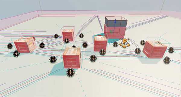
Figure 8–20. Level with cover and cover nodes
Running the Final Game
Next, while still in the Unreal Editor, change the default game type to ExampleCh8Game. Select the View ![]() World Properties menu item, and then set this value in the World Properties window.
World Properties menu item, and then set this value in the World Properties window.
Now run the game on the mobile previewer.Jazz bots should be dropping on your head and moving toward cover.Move your pawn around and you should see the bots trying to hide from you (see Figure 8–21 and 8–22). Ignore the message about the lighting needing to be rebuilt, as that does not have any effect on the actual gameplay.
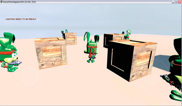
Figure 8–21. Bots taking cover from the player
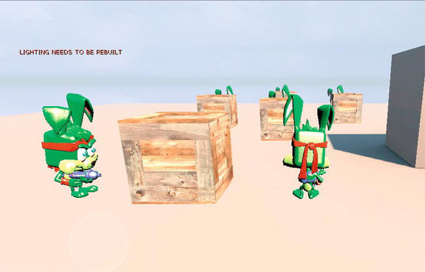
Figure 8–22. Bots taking cover from player
In-Depth Example Explanations
In this section we will provide more in depth explanations of key issues dealing with vectors, trigonometry, and 3D math.
Specifically we will cover
- How to position the camera in the world behind the player.
- How to apply a force to an object at a certain angle.
Third-Person Camera Positioning
In Chapter 3, we used third-person camera positioning to move the camera behind the player's pawn. The key issue is how to find the exact location to place the camera so that it is at a certain distance behind the player's pawn and makes a certain angle with the ground.
The key function in terms of moving the camera behind the player is the CalcCamera() function from the Jazz1Pawn class shown in Listing 8–12.
Listing 8–12. CalcCamera function from the Jazz1Pawn class
simulated function bool CalcCamera( float fDeltaTime, out vector out_CamLoc, out rotator out_CamRot, out float out_FOV )

{

    local vector BackVector;

    local vector UpVector;


    local float  CamDistanceHorizontal;

    local float  CamDistanceVertical;


    // Set Camera Location

    CamDistanceHorizontal = CamOffsetDistance * cos(CamAngle * UnrRotToRad);

    CamDistanceVertical   = CamOffsetDistance * sin(CamAngle * UnrRotToRad);


    BackVector = -Normal(Vector(Rotation)) * CamDistanceHorizontal;

    UpVector   =  vect(0,0,1) * CamDistanceVertical;


    out_CamLoc = Location + BackVector + UpVector;


    // Set Camera Rotation

    out_CamRot.pitch = -CamAngle;

    out_CamRot.yaw   = Rotation.yaw;

    out_CamRot.roll  = Rotation.roll;


    return true;

}
Here's what the code does:
- The camera's final position is the location of the player's pawn moved horizontally backward by the
BackVectoroffset vector and upward by theUpVectoroffset vector. - The
BackVectorpoints in the opposite direction from the player's front and has a magnitude ofCamDistanceHorizontalunits. - The
UpVectorpoints upward and has a magnitude ofCamDistanceVerticalunits. - The
CamDistanceHorizontalandCamDistanceVerticalvariables are calculated using the properties of a right triangle that were dicussed earlier in this chapter. - The
CamOffsetDistanceis the distance between the player's pawn and the camera.
See Figure 8–23 for a diagram.
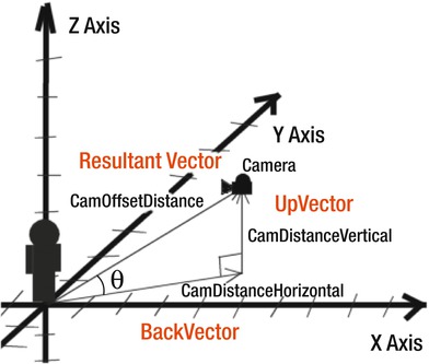
Figure 8–23. Third-Person Camera Diagram
The final position of the camera is calculated by adding the Resultant Vector to the player location. The Resultant vector is calculated by adding the BackVector to the UpVector. Graphically, to represent the addition of two vectors you put them head to tail with each other then draw the resultant vector from the tail of the first vector to the head of the last vector. CamDistanceVertical and CamDistanceHorizontal are scalar values derived from the CamOffsetDistance scalar value and the angle Theta which is the angle the camera makes with the ground. CamDistanceHorizontal is equal to CamOffsetDistance * cos(Theta). CamDistanceVertical is equal to CamOffsetDistance * sin(Theta).
Deriving a Direction Vector for Kicking an Object
In Chapter 4, we had to derive a direction vector for kicking an object in a 3D world. The issues involved finding the direction vector to kick the ball assuming a 2D world and then translating this vector into a full 3D world.
As part of determining the direction vector, we needed to first break it down into horizontal and vertical components. The key parts of the code in terms of setting the angle to kick an object are shown in Listing 8–13.
Listing 8–13. Kicking an Object
KickAngle = 15 * DegToRad;

ImpulseDir = (Normal(Vector(Pawn.Rotation)) * cos(KickAngle)) + (vect(0,0,1) * sin(KickAngle));

ImpulseMag = 500;
The general idea is to first get the normalized vector that represents the direction that the object will be kicked. Then you can multiply this vector by the magnitude of the force you wish to apply to the object.
The first thing you will need to do is build the direction vector. The direction vector is composed of a horizontal component which is the FrontUnitVector and the vertical component which is vect(0,0,1). See Figure 8–24.
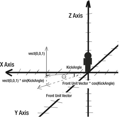
Figure 8–24. Building the direction vector
If we just added both vectors together then we would get a KickAngle of 45 degrees since the slope of the vector would be 1 since both vectors are unit vectors that have a length of 1.
To calculate the direction vector for an arbitrary angle is more complex. First let's find the direction vector for a KickAngle in 2 dimensions. See Figure 8–25.
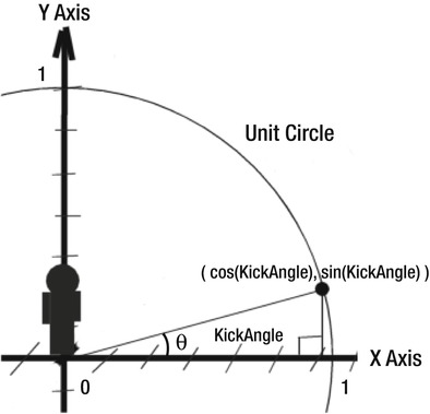
Figure 8–25. Calculating a direction vector in 2D
In Figure 8–25 you see the unit circle which has a radius of 1. According to the identities associated with a right triangle the horizontal value of the direction vector is cos(KickAngle) and the vertical value of the direction vector is sin(KickAngle).
Now we know how to get the direction vector from an arbitrary KickAngle on a 2D plane. However, our world is 3D so now we must somehow project this 2D direction vector into our 3D world.
We do this by multiplying the FrontUnitVector by cos(KickAngle) and the up unit vector which is vect(0,0,1) by sin(KickAngle) and adding them together to get the final direction vector in the 3D world.
Summary
In this chapter we covered vectors, vector addition, vector multiplication, dot and cross products using vectors. Next we went through a hands-on example that created a new cover node type where the user was able to set an angle of protection. If the threat was within this angle then the cover node provided protection to the occupant from this threat. Otherwise it does not. Finally we discussed in detail how certain things in previous chapters were accomplished such as the third-person camera and deriving the direction vector for kicking an object at a certain angle. The final few chapters are the framework chapters that will give you a good starting point for creating your own games.