
C H A P T E R 24
![]()
Construction of a packetC Executable
Based upon the compiler and development environment that you are using with packetC, the tool-chain and your course of action to create a packetC application may vary. As of the time of writing, there is only one available tool-chain that supports the various vendor execution platforms. The following discussion provides some insight into the tool-chain and the methodology behind building a packetC application. Refer to the PacketWorks IDE User Guide for a complete walk-through of the development environment and the associated options available for installation, development, and debugging of an application.
The tool-chain overview is shown in Figure 24-1 below, walking through how packetC source code is compiled into an executable and then merged into a configuration for a run-time package of applications that can be loaded onto a processor blade. Object RAVE Code (.ORC) is the output format of a packetC application being compiled and is similar to an executable found on traditional computing platforms. Similar to modern PC execution environments where dynamic linking is required, executables require configuration to identify how they apply to their surroundings such as network input and out interfaces. One or more .ORC executables may be placed in an Application Deployment Package (.ADP) for loading onto a system which includes wiring diagrams of the “virtual patch panel” that turns each packetC application acting as a “virtual appliance” into a completed deployment environment for a processor blade tying virtual interfaces on the applications to physical interfaces on the blade.
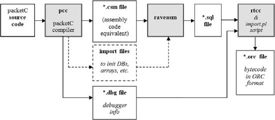
Figure 24-1. Tool-chain overview
Figure 24-1 provides a view into the tool-chain behind packetC. The high-level packetC source code is compiled into the respective assembly level opcodes (RAVE) which are in turn compiled to the binary opcodes in the executable ORC. Along the way, data files are processed to provide a means to initialize data sets at execution time as well as output to support the debugger.
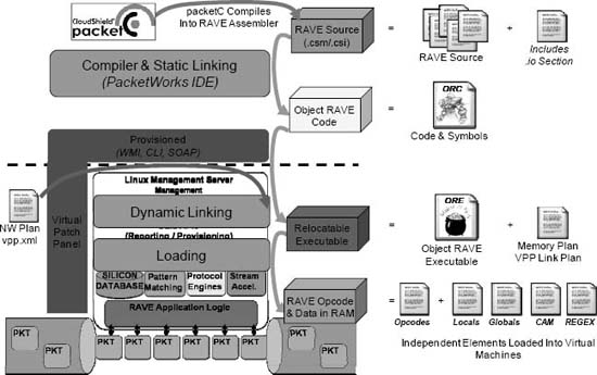
Figure 24-2. Exploded view of packetC tool-chain and intermediary files
The diagram shown in Figure 24-2 is another view into the tool-chain shown more logically with the output files and formats shown along the right. This provides a view that ties a bit more into the memory regions of the processor blades and the logical subsystems contained within those blades. This information is linked and loaded during provisioning to the platform.
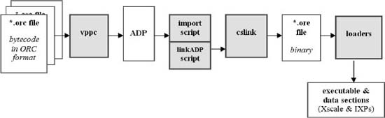
Figure 24-3. packetC tool-chain flow of compilation
As an ORC represents a single application, and processor blades can execute a collection of applications combined together, there needs to be a method for depicting their interaction and managing memory allocation. This is performed through a virtual patch panel configuration (vppc) that generates an XML data file tying a collection of packetC applications together (Figure 24-3). These are stored in an ADP which is then used by the processor blade on-system linkers and loaders to move the execution logic into the control-plane and data-plane processors. The final memory map of all applications in memory on the processor blade is the object rave executable (ORE) which represents the state of memory maps. Noting that new applications can be loaded without updating other applications or their memory areas, the ORE is a dynamic configuration known to the processor blade.
Multiple individuals will generally be involved in the development of an application as well as the definition and construction of an application deployment package loaded onto a system. The actors, in formal modeling of the relationship of the lifecycle of an application being developed to being deployed, are shown in relationship to each other in Figure 24-4.
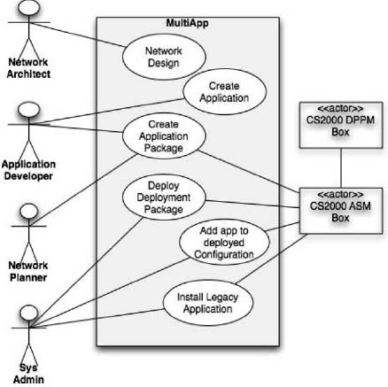
Figure 24-4. Representative actors working with packetC virtual appliances
Developers will code an application, and compile and debug it within a development environment. The result of their efforts will be an executable, an ORC, that can be shared with a network planner. The network planner will use a set of modeling and configuration tools, such as a virtual patch panel configurator, to generate an application deployment package, ADP, for a target system. This is provided to a system administrator to deploy on one or more systems. This simple conceptual model is what is represented above and the tools shown throughout this chapter provide insight into what is leveraged to accomplish these steps.
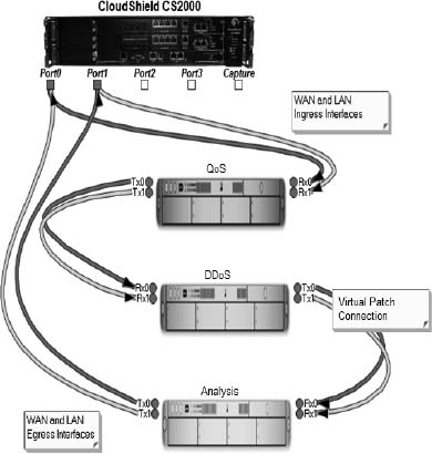
Figure 24-5. Simple virtual patch panel containing three packetC virtual appliances
Upon completion or acquisition of one or more applications (ORC), an ADP will be constructed modeling how the applications will logically operate on the processor blade. A view of a virtual patch panel contained within the ADP along with the applications is shown in Figure 24-5. Each virtual appliance shown represents an ORC, and the graphical connection of the wiring diagram will result in the generation of the XML file stored within the ADP describing the entire load for the processor blade. An XML file is part of the ADP describing the virtual interfaces on applications as well as their connectivity to physical interfaces on the target platform (CS-2000 DPPM-510 5-port GigE Blade shown).
A View into the CloudShield PacketWorks IDE Tools
The following descriptions and images within this chapter provide a view into some of the common and more unique elements built into the integrated development environment supporting packetC. With packetC targeting parallel systems with a focus on networking and content processing, there are several tools the developer will require to support completion of an application. In particular, the development of a network application which has no user interface and a stream of packets as the only input device, changes the notion of a debugging environment. Furthermore, the crafting of regular expressions and evaluating application performance drove the creation of new tools. In addition the commonplace tools for team development are also present. . These figures are from the CloudShield PacketWorks IDE 3.1 which uses an Eclipse-based development environment for the creation of packetC applications.
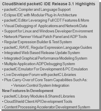
Figure 24-6. CloudShield PacketWorks IDE 3.1
Many of the key features of the IDE are shown in Figure 24-6 along with features that are coming in upcoming releases. The specific features may vary from one vendor environment to another as well as releases from CloudShield. However, what is important to focus on is the supporting tools to address the notion that packetC operates within an environment presuming capabilities being performed in the underlying operating system or virtual machine. In particular, the receipt and transmission of packets is scheduled and managed by the operating environment. Tools that perform configuration of this environment including the connection and flow of packets between multiple packetC applications are not common to a Linux or Windows platform. Furthermore, providing tools for modeling regular expressions is important when this mechanism is the foundation for search sets and their ability to perform unstructured content processing. While this book cannot tackle nor does it intend to serve as a means of stepping through the constructive nature of the development process and tools required to build and debug for a given platform, it is important to gain a sense for the different types of tools often necessary for developing packet processing applications in packetC.
Developers using the CloudShield PacketWorks IDE for packetC will receive a manual describing the IDE and all its tools as well as a POSIX regular expression language guide in addition to packetC samples and highlighted deviations from packetC that are specific to a target platform.
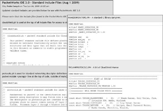
Figure 24-7. Standard include files on packetC.org
Programming in C is often as much about the art of leveraging include files as it is about knowing the actual grammar of C. In the same manner, packetC developers will craft and leverage numerous include files in order to simplifying the development of applications. All packetC applications need to leverage a target platform include, such as cloudshield.ph, as well as leverage a suggested protocol include file, such as protocols.ph. While provided with an IDE, these are also subject to updates due to the release of new platforms or errors. The packetC.org forum is the location for finding updates to platform include files as well as the many standard include files discussed and referenced in Chapter 27. Furthermore, the community of developers will often share samples and include files with helpful sets of constants, as in the case of NAMEDOPERATORS.PH, or code libraries as seen in Figure 24-7.
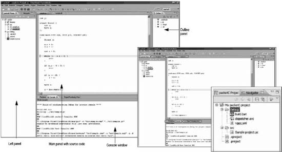
Figure 24-8. packetC Eclipse environment
Even though packetC is a new language, it is able to take advantage of the breadth of features in open development environments such as Eclipse. The packetC tools are installed into the IDE as plug-ins and allow for development of complementary management applications in Java and C in the same environment as packetC development. Standard features for version control, enhanced C style visual editors and tool-chain output in console windows are fully supported as shown in Figure 24-8.
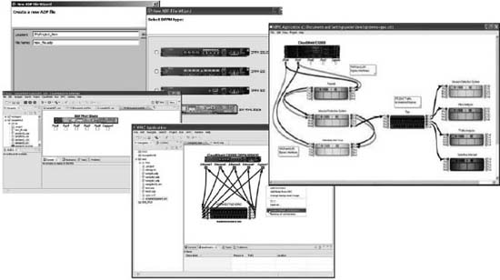
Figure 24-9. Virtual patch panels for connecting packetC applications
Most examples of network applications map directly to a physical view of appliances, such as routers, switches, firewalls and intrusion prevention systems. A given host executing packetC applications may need to perform the equivalent of more than one physical appliance. A packetC application, when compiled into a resulting executable also presents a view to the operating environment depicting a number of virtual interfaces and the resources required to load the application. For target systems supporting more than one application, similar to a modern virtual machine based server deployment, there needs to be a way to depict how to flow packets from the physical interfaces on the host platform to and through each virtual appliance developed in packetC. The virtual patch panel configuration (vppc) tool shown in Figure 24-9 provides a graphical interface to wire up a network of virtual appliances in the same manner that a network engineer would diagram how they would wire up their physical appliances.
Each different processor blade in a target host may have different physical interface counts that would result in a different configuration of virtual appliances. As packetC applications can dramatically vary in their capabilities, this may also result in a wide variety of virtual interfaces to be required such as seen in the number of ports in a switch versus a firewall. Some packetC developed virtual appliances may even create copies of traffic resulting in conditions where there are more virtual interfaces in a virtual appliance than physical interfaces in the host platform. The rightmost image in Figure 24-9 shows the case of an inline virtual appliance (left side middle) copying traffic to another virtual appliance (middle appliance) that is performing load distribution to four (right) different virtual appliances by protocol.
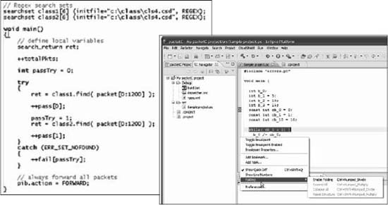
Figure 24-10. C style editor for packetC
With the introduction of many new keywords and grammar constructs in packetC, traditional C editors may struggle in Eclipse to provide the desired enhancements to the development process. Enhanced packetC editors are available that provide keyword highlighting, integration with debuggers for setting breakpoints, as well as traditional stylistic templates with packetC style guidelines implemented as defaults. Figure 24-10 shows a section of code within the IDE with some of the highlighting enabled. Developers are not required to leverage any specific editor for packetC, however, the availability of tools with features that provide integrated checking of syntax, coding style templates and integration with version control and debugging solutions can make the development process flow more quickly.
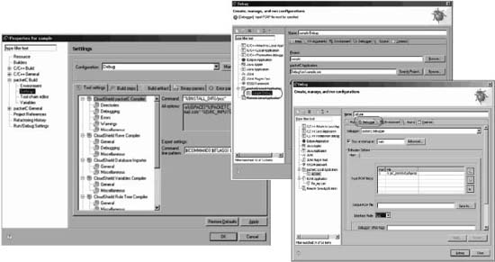
Figure 24-11. Tool-chain control options
While many packetC applications will be small and focused in their size and scope, others may be the results of large team efforts building very complex solutions. As packetC applications grow, so do the demands upon the development environment to aide in team-based development and introducing complex data sets for debugging. Data management becomes especially critical in networking applications as the user input and output may be collections of packet captures streamed through virtual interfaces and log files showing resultant data sets. A number of configuration options are able to be configured for a packetC project as shown in Figure 24-11 to support compilation from numerous sources as well as to support the debug environment.
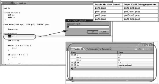
Figure 24-12. Visual debugging in packetC
While many of the language enhancements introduced in packetC can reduce the number of lines of code compared to a C application performing identical functionality often by an order of magnitude or more, bugs still crop up. An integrated environment with break points, data watch settings and run-time stepping functions are critical to debugging applications where capture files provide cryptic means supporting only black box debugging. Figure 24-12 shows some of the simple integrated debugging features in packetC development environments.
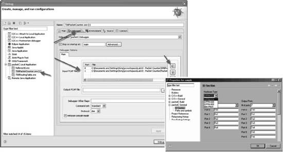
Figure 24-13. Multiple packet capture file coordination
With multiple virtual interfaces on a packetC virtual appliance, each requires a set of input conditions and resultant output collections of packets that can be analyzed during and post debugging. The IDE must coordinate the source packet captures, generally stored in .pcap format for use with tools such as Ethereal. In Figure 24-13 above, the port numbers shown next to files names in the window at the left maps the capture file to a given virtual interface. The dialog shown at the right provides a configuration tool to specify the number of input and output interfaces to associate with a given virtual appliance under test. Network applications pose unique debugging challenges compared to traditional applications where keyboard, mouse, and video interfaces are the common input and output devices under the control of a human tester. Furthermore, traffic generation equipment for testing network devices works well to flood a device at speed, but often poorly to send a single packet into a system or coordinate specific packets to arrive from disparate interfaces at the same time. Finally, if a virtual appliance expects its output to be the result of another virtual appliance, such as a virtual Ethernet firewall sitting behind a virtual SONET to Ethernet router, the input conditions of one solution may only operate properly using the output of another. A packetC debugger must account for these conditions among others.
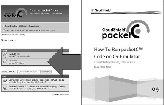
Figure 24-14. Emulating the packetC operating environment on Linux
Throughout this book, considerable time has been spent on the requirements packetC places on the host system as well as the unique features provided by processors that execute packetC developed applications. In Appendix B a view into hardware designed specifically to process packetC applications is shown. While highly tuned systems are required at this time to process network traffic at 10 Gigabits per second or higher, in development and in small scale deployments, an emulated environment on a traditional computing system may be all that is required. An emulator is available on packetC.org that provides a simple command line tool executing in Linux to execute a single packetC virtual appliance. With this emulator, a development environment, and the investment of some time with the associated instructions as shown in Figure 24-14, a newcomer to packetC can craft and test their first packetC applications on an available Linux system.

Figure 24-15. POSIX regular expression evaluation plug-in
Within packetC is buried yet another language, namely POSIX regular expressions. While network headers are easily descripted using structured methods supported by packetC descriptors, the Internet era has created new protocols without any industry standards of controls which are predominately represented in textual forms rather than byte aligned fields. To process unstructured data, such as HTTP and HTML, regular expressions provide a means to express an algorithm to instruct the system how to find data of interest within the payload of a packet. Just as packetC needs to be debugged, so do regular expressions. While many simple tools exist to evaluate regular expressions, packetC applications often leverage multiple tables of regular expressions that need to be tested against different data sets. The image in Figure 24-15 highlights one view of a regular expression evaluation plug-in that allows for the editing of expressions and testing against a set of sample data ensuring that the resulting offsets of searches are as expected by the developer.
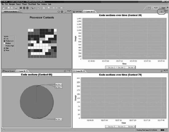
Figure 24-16. Multi-context real-time debugger utilization
While functionality can be tested in a debugger on a development platform, often real-time debugging is required to evaluate an application under load. Figure 24-16 shows two simple views of a packetC application under load. The first, shown at the top is a view into the multiple contexts. As packetC applications are designed to run on multi-core systems, determining utilization under load and hot spots, often tied to contexts stuck in endless loops, is best seen by watching metrics of an operational system. The figure above is looking at a 96 core system where 96 packets are able to be processed at any given time and the color, or gradation in grayscale, represents load level. Another tool that is useful is the measurement of time by section of code. Often tuning focuses on the reduction in the lines of code, while packetC focuses on the reduction in the lines of code during a given period of time across a number of packets. Sometimes it is better to determine which sections of code are used most often and reduce their code size, potentially at the detriment to the number of lines of code in another section less often utilized. Developing graphs of time in code sections as a measure of a system under load provides critical tools for moving applications from poorly performing data rates to extreme high performance. Real-world examples have seen code performing at a few hundred megabits per second on a system after weeks of developer tuning result in multigigabit performance after just a few hours of tuning when looking at the application with these tools.
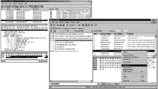
Figure 24-17. Viewing and editing packet captures
Throughout this chapter the reference to packet captures as an input and output of packetC virtual appliances has been made. Within the integrated development environment the captures will be present in project directories and the tools to view and edit packets as expected features. Figure 24-17 provides a view into the traditional tools used to view and edit packet captures, such as Ethereal and Packetyzer, respectively. While Linux systems generally provide command line tools to capture and view dumps of the packets on the network interfaces, it is fairly rare to find tools to edit and craft packets from scratch. As solutions are focused on processing traffic found in a WAN or cloud environment, it is often difficult to have ready access to captures of the traffic of interest. Furthermore, in solutions that are security focused, looking for specific exploits in the wild in network form can be quite cumbersome. Using tools to edit capture files of only the packets of interest and then being able to insert data of interest to specific packetC subroutines dramatically reduces the time to perform unit testing.
This chapter introduced some of the underlying mechanisms implemented with a packetC tool-chain that support the simplified packet processing environment present in the packetC grammar. Furthermore, as those expected capabilities simplify development, they also leave a lot of open questions about how choices are implemented that affect the processing environment. The brief walk-through of some of the unique configuration elements and tools to support development of packetC provides a cursory view into how development of packetC applications will often vary from traditional C projects, even for networking. Further information can be found in user guides focused on the packetC integrated development environment. However, a cursory understanding of the tools and expectation of tools placed upon an IDE to support the packetC developer should provide the requisite answers to how a developer can accomplish successful development leveraging unique packetC functionality such as search sets. The examples above are not inclusive of everything required or present, but should at least introduce the concept of the differences in tools for developing applications that live within the network.