

Construct a Concept Sheet
Step Three
A basic understanding of the fault and the conditions that caused it are of paramount importance in understanding any type of defect. You must be able to change any unfavorable conditions that affect quality. So, as with all defects, determining what caused the flaw is important. Having focused on the fault in the previous chapters, it is now time to consider its cause.
Enter the Concept Sheet
Developing a concept sheet is the third step in formulating a proficient plan of attack for understanding the cause of a problem and solving it.
Each problem solver brings acquired knowledge to a study. Because of this, it’s important to leverage the knowledge of the whole team when developing a method to solve a particular problem. Your problem-solving team’s primary activity is to create a concept sheet. This sheet will help you determine which conditions are contributing to the problem.
A concept sheet defies precise definition. It can be a rudimentary sketch of a condition, or an intricate explanation of a process. A concept sheet is therefore anything that enables an observer to conceive, visualize, or create a theoretical model that simplifies cause identification. The weakness of developing concept sheets is the lack of innovation due to investigator inexperience. To help those lacking experience, and to aid those who need to hone their problem-solving skills, I provide many examples.
The following concept sheets were used to identify actual problems. Each sheet includes a brief explanation so you can apply it to related problems.
Poor Fusion Weld Concept Sheet
Problem: A heater hose assembly bracket was subject to broken welds before installation. Evaluation of the pipes showed there to be discoloration—signifying heat transfer—but no penetration at the weld-bead mating surfaces. The concept sheet we developed (see Figure 3-1) provided visual clues that allowed us to address inadequacies in the weld operation.
Solution: We realized it was necessary to change the weld direction from a vertical to a horizontal pass across the pipe and bracket interface to ensure quality welds. This new pattern was required because the process was not capable of ensuring proper flush mating between the components each time.
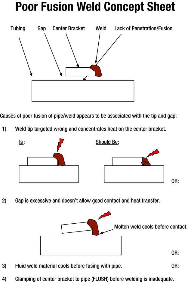
Figure 3-1. Poor Fusion Weld Concept Sheet
Front Cover Oil Leak Concept Sheet
Problem: An engine front cover oil leak caused process rejects and affected first-time quality. We developed a concept sheet (see Figure 3-2) that facilitated the recognition of the possible causes. The sketch indicated that the fit in areas where the parts interfaced, damage, and the lack of a quality casting could all be creating an oil leak.
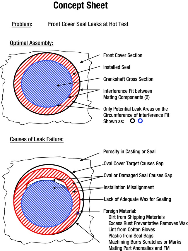
Figure 3-2. Front Cover Oil Leak Concept Sheet
The sheet shows two sketches that were used for comparison. The top sketch indicates the optimal assembly of the components. We knew that the most significant leak areas were on the circumference of the mating components, which generally require a firm interference fit to ensure sealing.
The bottom sketch summarizes the problem conditions that we considered when attempting to define the possible leak paths. The concept sheet identifies the conditions we knew we should consider in addition to other visual inspections.
The leak conditions could include:
Porosity in the casting
Porosity in the seal
Oval gap in the cover
Oversize cover hole
Oval or damaged seal
Installation misalignment
Machining burr, scratches, or marks
Foreign material, such as dirt from packaging, lint or strings from gloves, packaging particles, or excess rust preventive
Sealing lip damage
Solution: The leak was accompanied by pinhole porosity inherent in the casting adjacent to a boss area,1 but 0.020 inches below the surface. Changing the boss location and the sectional area adjacent to the porosity-sensitive area eliminated the porosity. It appeared that the thick and thin metal sections solidified differently and voids were created when proper metal flow was not provided. Visual observation of the leak conditions was therefore rewarding.
What follows is a general template you can use to find leaks of all kinds, a common occurrence in most manufacturing facilities.
Problem: All components containing castings, seals, gaskets, welded components, machined finishes, and so on, are subject to leaks that affect first-time quality. The concept sheet (see Figure 3-3) provides sketches of conditions as they should be, as well as how they may actually be. The difference between the two conditions provides clues that you can use to analyze the leak. Parts should mate, fit flush, and have the proper finish and orientation. When they don’t—because of mismatches, voids, damage, poor finish, poor alignment, or positioning—leaks result.
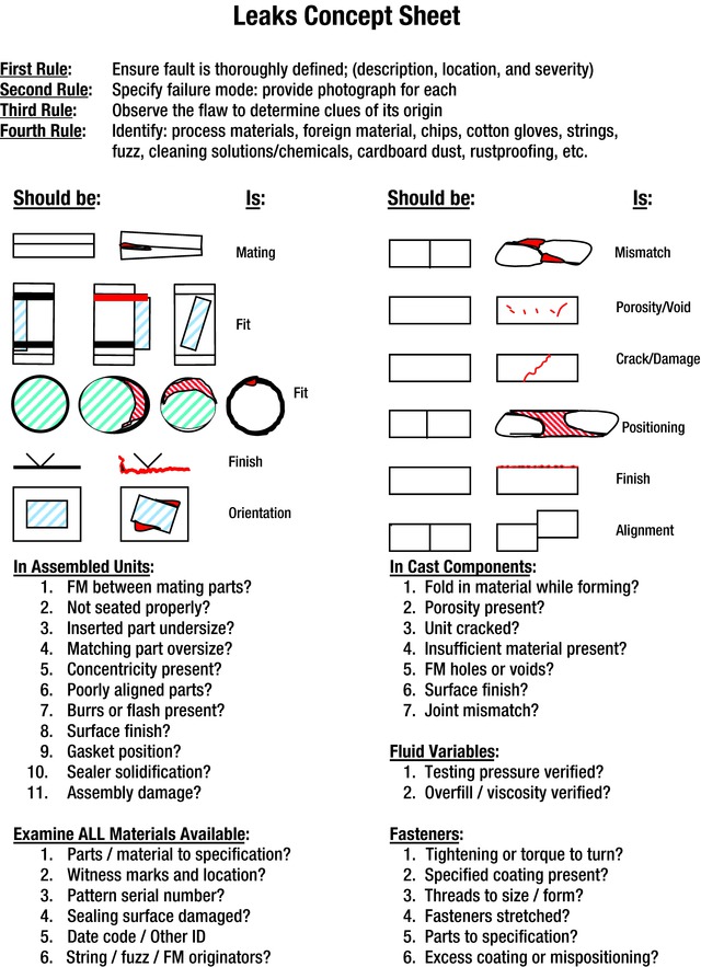
Figure 3-3. General Leaks Concept Sheet
The top of the sheet also lists some useful rules that you can follow when you encounter leaks. The four rules are self-explanatory and will help you define the leak. First, you must ensure that the fault is properly defined. You then specify the failure mode2 and capture it in a photograph if possible. Next, you identify potential origins of the leak; sometimes there are multiple causes. And, finally, you identify foreign material if it is present.
As you can see, the sketches are augmented by the clues presented below them. You should consider casting, assembly, fastener, and pressure variables. The lack of O-rings, misplaced gaskets, missing sealants, and damaged surfaces will become apparent with cursory examination.
In some cases, the problem may stem from an interaction. Interactions are when two things that have no individual effect adversely affect an operation in tandem. For example, if molten iron is spilled onto a dry floor during a foundry operation, it will splash and disperse. If the spill happens to fall on a water-soaked floor, an interaction is imminent. The heat from the molten iron changes the water to steam, which frees itself from the iron with explosive strength. This interaction can be violent.
In a later example, there is a condition where the application of the proper amount of grease provides an adequate seal if no major foreign material is present. It is even possible to have some foreign material present and still get an adequate seal. However, the presence of a small amount of foreign material may result in a leak if there is insufficient grease to provide a robust condition for sealing. This is also an interaction between variables.
Using the leak concept sheet assists you in identifying and solving most direct-effect leak causes. You might also be able to identify interaction components using this sheet, but you’ll have to perform additional evaluations to be certain.
![]() Note Concept sheets are applicable to all types of problems. You can express them as Venn or block diagrams and apply them to problems beyond traditional manufacturing, such as with sensing devices, electrical components, and many other areas.
Note Concept sheets are applicable to all types of problems. You can express them as Venn or block diagrams and apply them to problems beyond traditional manufacturing, such as with sensing devices, electrical components, and many other areas.
The following explanation for a sensor failure that was rated as a “No Trouble Found” (NTF) by one investigator was later resolved under reexamination at the supplier. This case study uses an NTF concept sheet (see Figure 3-4) that you can use as an example for problems that initially don’t seem to have a cause.
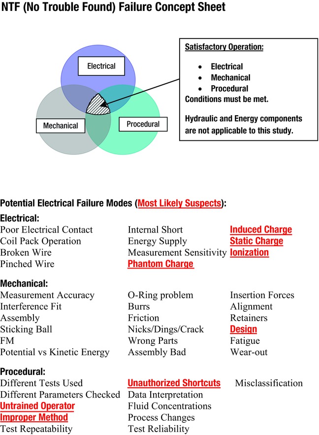
Figure 3-4. No Trouble Found (NTF) Concept Sheet
Problem: Failed components at the assembly plant were found acceptable during reevaluation at the supplier location. The supplier suggested there was a phantom ionic charge that was generated in a sensing device when a tramp element (a contaminant) was allowed to interact with a transistor. The supplier further suggested that the sensor components had to be redesigned to shield the individual resistor components. This shielding was meant to eliminate the attraction between the highly negatively charged transistor and the positive ions generated by the raw material.
We found this supplier-proposed correction to be costly and unnecessary.
Naturally, the first thing we did to begin to solve the problem was to develop a concept sheet. The sketch on the NTF concept sheet in Figure 3-4 shows the relationship of the characteristics (electrical, mechanical, and procedural) that must be present in the installation of electrical and mechanical sensing devices. (Depending on your problem, hydraulic and energy components may also come in to play. They were not included on this diagram because they were not applicable to the study.) The overlap indicates that all three conditions must be present to allow satisfactory operation.
The table below the sketch identifies conditions that could affect each of the individual characteristics shown above. We considered the items shown in bold the most likely suspects before the investigation began. This table, however, did not restrict the study. Rather, it served to make the investigator more aware of the conditions that may have been present.
We knew that if any of the three input conditions were unsatisfactory, the sensor would not operate properly. As mentioned, since the sensor was acceptable at the supplier but failed upon installation, we had to return the failed sensor to the supplier for reevaluation. This required a costly rework operation in which the flawed component was removed and replaced.
We shipped the sensors that failed after installation overnight to the supplier for final analysis. The supplier retested the sensors on the test stand and found that they operated satisfactorily. The resulting report informed the customer that there was no trouble found (NTF) with the components. They were acceptable.
This type of result causes consternation, because it does not identify the problem and will result in recurrence of additional failures in the future. Upon pressing for a more definitive answer, the supplier reported a possible ion flow reason that proved to be incorrect. We needed to continue our study and so we did a full analysis, as shown in the parallel engineering study (see Figure 3-5).
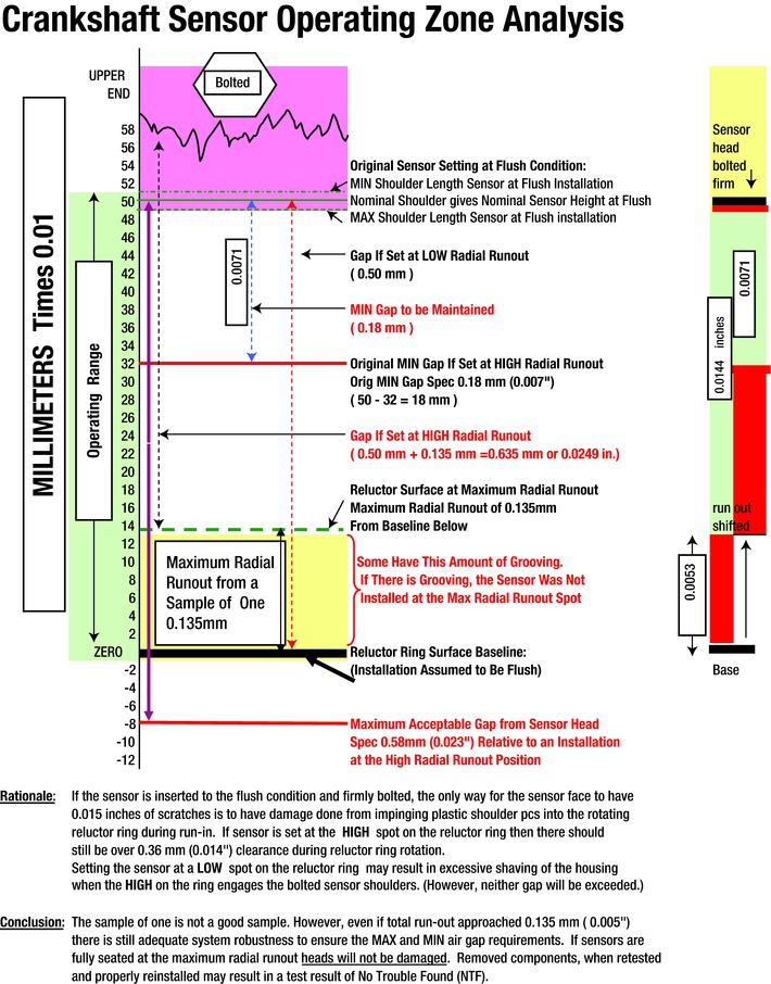
Figure 3-5. Crankshaft Sensor Operating Zone Analysis
Problem restated: Assembly failures were causing rework and were affecting quality because engines were failing tests during final testing. In one case, an important sensor that failed was positioned adjacent to the crankshaft within an engine assembly. Again, it was initially a case of NTF.
To start, we developed a concept sheet (see Figure 3-5). This analysis revealed that the sensor failures occurred only when the sensor was not inserted to the full depth. We found that the sensor could not be installed too close to the crankshaft. It could only be installed too far away from the crankshaft. If it was not installed fully, it could exceed the maximum sensing gap, causing failure.
As you can see, we sketched the sensor in position with a potential radial run-out condition to reduce the ambiguity. Once the sketch was made, we could visualize the bolted sensor and the interference forces that acted upon it. But while the sketch provided valuable clues, it did not provide conclusive evidence of the condition causing the malfunction.
Only after we created the operating zone analysis sketch did it become clear that it was not possible to violate the minimum gap. It was only possible to exceed the maximum gap if the sensor was not bolted tightly and flush to the crankshaft properly.
As a process comparison, look at Figure 3-6. Note the difference in skills and effort required to solve the sensor problem. It is sometimes faster and more convenient to compare the differences between the good and suspect parts.
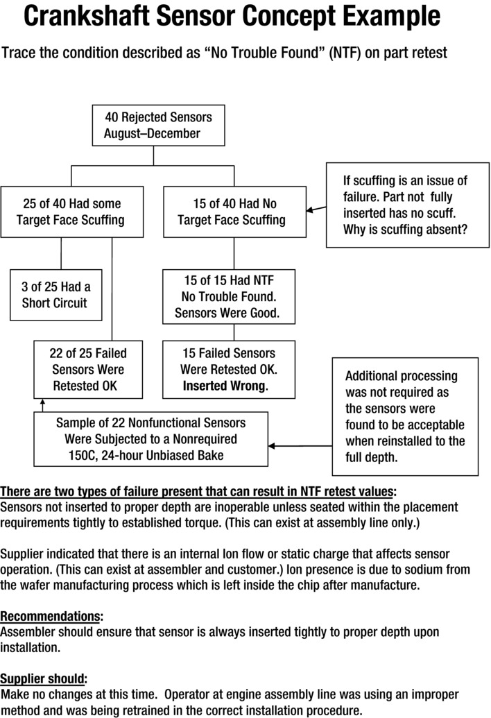
Figure 3-6. Crankshaft Sensor Analysis Block Diagram
There are two types of failure that can result in NTF retest values:
Sensors not inserted to proper depth are inoperable unless seated tightly within the placement requirements to established torque. (This condition can exist at the assembly line only.)
Supplier indicated that there is an internal ion flow or static charge that affects sensor operation. (This can exist either at the assembly line or with the customer.) Ion presence is due to sodium from the wafer-manufacturing process that is left inside the chip after manufacture.
Solution: We retrained assemblers to ensure that the sensor is always inserted tightly to the proper depth upon installation. In addition, we recommended that the supplier make no changes at this time. Operator at engine assembly line was using an improper method and was being retrained in the correct installation procedure.
Case note: The example in Figure 3-6 shows the summary of the study of the defective parts. Again, comparing conditions of good to bad parts proved useful in determining the problem. Since almost all of the rejected parts retested satisfactorily at the supplier, it was apparent that scuffing was not a cause of the problem. However, it was a useful clue.
The fact that a large proportion of the rejected parts had no scuffing was relevant, as it exhibited a visual clue to the installation operation. The failures were caused by an assembler at the engine assembly plant who failed to fully seat the sensor before tightening, as evidenced by the lack of full contact scuffing. The inattention to this task caused an excessive operating gap and continuation of a surface charge. After training, posting instructions, and auditing, the problem was prevented from recurring. We identified the clues to this condition via the concept block diagram—although the scuffing did not cause the problem, it provided a clue that led to its solution.
Initially, these examples may appear too complex or difficult to understand. However, as you attain more problem-solving experience, recognizing major differences and influences becomes easier. You’ll find that you quickly gain experience after working on one or two problems.
Bent Ignition Coil Connector Pins
This section considers a different manufacturing problem, which uses a product flow plan and a mating part to correct a problem at a car assembly plant. Workers were unable to connect the car-wiring harness to the engine after inserting it into the chassis. The plant reported that the engines had bent pins that prevented electrical connection. Workers had to relocate the vehicle and engine to a rework station where the defective engine was repaired or a replacement engine was installed. This was a time-consuming and costly operation. This problem also created what is referred to as a “spill,” because there were hundreds of engines in storage awaiting shipment and they had to be sequestered to prevent delivery to the patron plant. Each stored engine required inspection before shipment.
Problem: A vehicle assembly plant reported rework because of bent ignition coil connector pins. The only identification available at the time of defect detection was the engine serial number, which was not entirely traceable for each component or operation. Because the engine was already installed in a vehicle, the required repairs were disruptive and costly.
We created a list of the data from each of the different potential sources of the problem.
Available from the supplier:
Different suppliers who provided the components
Number of manufacturing cavities for each component
Blueprint tolerances
Percentage fallout (percentage of products that were defective)
Available from the engine plant:
Conveyor saddle number used for engine assembly
Engine identification number
Six identical test stands used to check engine final test
Damaged pin location
Available from the vehicle assembly plant:
Engine identification number
Damaged pin location
Classification of failures
Individual or group failures
The first thing we did was collect the information required to generate clues.
In most cases, variable data is preferred over attribute data because it is more descriptive and lends itself to statistical analysis. In this case, however, it was better to visually observe the process to determine if a precondition of pin misalignment was present (see Figure 3-7). The bent pin on the left came from test stand 3110, whereas the acceptable pins on the right came from test stands 3070, 3080, 3090, 3100, and 3120. The area requiring investigation, therefore, was test stand 3110.
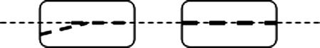
Figure 3-7. Bent Ignition Pin Drawing
A Focus on Process: Engine Assembly Routing
It’s important to look at process flow. If you can follow the process and determine the point at which the component becomes damaged, you know something about which step is causing the defect. After some detective work, we discovered that the parts were acceptable at the engine plant but unacceptable at the assembly plant. Consequently, the damage was caused at the prior engine assembly or test operation, which was at our engine plant before the engine was shipped to the car assembler.
When we assembled components on the conveyor at the engine plant, the engines passed through one of six test stands before being shipped to the vehicle assembly plant. At the assembly plant, they are installed into vehicles and tested to ensure conformance with customer requirements.
We decided to evaluate if the problem found at the vehicle assembly plant was a result of engine plant problems or if it originated after leaving the engine plant. If components are found to be satisfactory at the end of a process, the problem is not with the previous operation(s). However, if any bent pins are found internally, the defect was caused internally and each previous related operation’s output must be checked.
Because the bent pin condition could reasonably be the result of a twisted interference fit or an assembly problem, we acquired a matching component that was used in an assembly. This we used at the end of the engine plant manufacturing process to determine whether the collector pin connection could be made without difficulty. (A mating connector was used.)
A sampling of all connectors going down the line indicated difficulty in installing the connector on engines 146, 149, 151, and 153, which were all processed in sequence on test stand 3110. Since 4 of the 15 engines had a bent pin, and these engines were all tested on test stand 3110, that machine was shut down and scheduled for repairs. None of the other five test stands produced bent pins.
The clue that indicated which areas to investigate is shown in the Engine Routing example (see Figure 3-8) by the broken dotted line. Finding the cause requires an in-depth analysis of the station and the interacting components to ensure problem elimination. Without these clues, an investigation becomes excessive and time consuming.
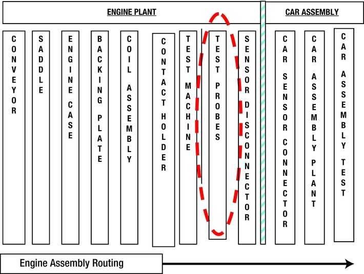
Figure 3-8. Engine Assembly Flow Path
Solution: A bracket with a broken bolt that held a probe in place was creating the bent pins. To ensure alignment with the connector on test stand 3110, we replaced the bolt-bracket assembly. The bolt was replaced in addition to the bracket, because the bracket’s dimensional correctness was askew.
After making the repairs, the engine plant suffered no additional bent pin damage. The line was then audited with a matching connector component at the start and end of each shift. In addition, they checked the sequestered stock to ensure that no more defects would reach the customer.
The strongest clue leading to a solution was when we determined that all the failed assemblies came from the same test stand. However, replacing the bolt didn’t mean the close of the project, because there was a reason that the bolt broke.
The assembly bracket required revision to allow proper seating of the bolt, and the damaged probe was replaced. One of the results of the bent pin problem was that the engine plant audited daily for bent pins, which prevented other malformed pins from being shipped to or reaching the assembly plant.
![]() Note These examples show how using a concept sheet in form of a diagram, routing sheet, or a sketch is important to problem analysis. The concept sheet allows the investigator to formulate the scenarios most likely to be present. You can use these scenarios to determine the most useful steps that can be used in a plan of attack.
Note These examples show how using a concept sheet in form of a diagram, routing sheet, or a sketch is important to problem analysis. The concept sheet allows the investigator to formulate the scenarios most likely to be present. You can use these scenarios to determine the most useful steps that can be used in a plan of attack.
Figure 3-9 shows a PCB process flow map, which is an outline of the routing process for the manufacture of an electrical PCB board. By starting at the upper-left corner and following the directional arrows as specified by the answers given to the questions, you can follow the progress and read the process controls and steps specified in the blocks on the right side of the sheet.
Summary
In every case, you have to address any problem you identify. You must put corrections in place to prevent recurrence. There must also be a plan to ensure that the problem will not resurface. Once you encounter a problem, it is prudent to assemble a file that can be used at a later date to provide information about the cause of the problem and the solution that you initiated. The lessons learned should also be reflected in changes to the design and process FMEA (failure mode effects analysis), as well as the control plan and job instructions for the process. These changes are made to ensure that the conditions that caused the problem are addressed in the design and quality planning for similar future products.
Using visual aids in generating clues for a plan of attack help you problem solve. This process includes evaluating the considerations and collecting the data, discussed in the following chapters. Before moving to data collection, however, I will discuss evaluation considerations for your plan of attack. You can evaluate these scenarios in order to determine which one provides the most influence and can be used in your plan of attack.
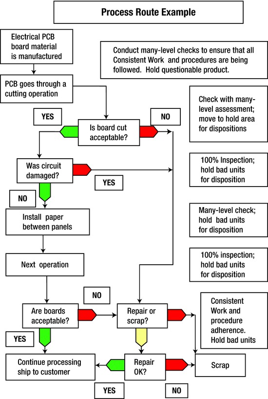
Figure 3-9. PCB Process Flow Example
1Boss is a term used in molding operations to describe the knob-like presence of some solidified molded material that is intended to be machined and drilled to allow the attachment of components. It is a mounting point for fasteners.
2Failure mode is the description of the method of failure. A component might have failed because it is cracked, mismatched, or scratched, depending on the acceptance criteria used.