

Torque-to-Turn Example
This appendix is included to reinforce several important points that were discussed earlier in this book. These include the need to observe and walk the operating system, the need to observe all possible clues, the need to understand how tiny some clues can be, the need to identify the most prevalent failure location, and the need to ensure that your suppliers agree to get prior approval for any changes they make to materials or processes on their end. Let’s look at how all these points play out in a typical manufacturing problem.
Sometimes, two independent conditions can contribute individually to create torque-to-turn problems. In this case, the pistons were supplied by different suppliers.
In this example, an assembly line was used to manufacture two types of engines. The engines had dissimilar faults. One engine had torque-to-turn failures, which means that the force required to turn or spin the crankshaft in the engine assembly was too high or restrictive. This was engine 2 in the on the right side, in Figure D-1, where the torque-to-turn flaw is indicated as “dimensions wrong.” The other engine, which was used for comparison, did not have this similar problem. The following discussion explains what we found as we were completing rework to refurbish torque-to-turn, test-engine failures.
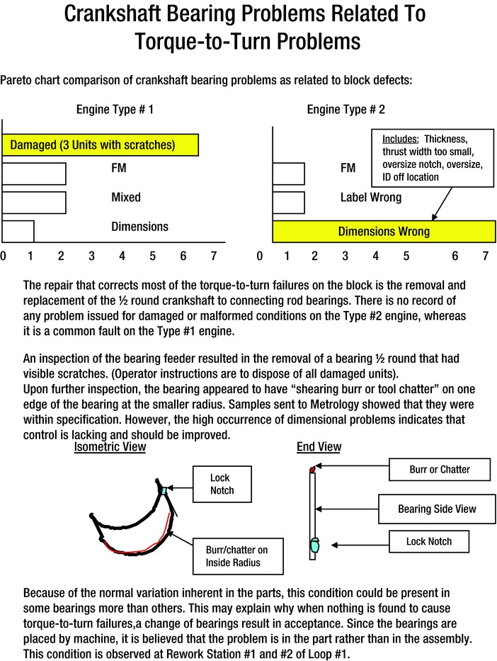
Figure D-1. Engine Torque-to-Turn Failure
The connecting rod bearings were found to be to specification, and there was normal variation inherent in the parts. But there appeared to be a small mark on the lock notch part of the bearing. This mark, observed at a rework station on the assembly line, was present in some bearings more than in others. This may explain why, when nothing was found to cause the torque-to-turn failures, a change of bearings resulted in acceptance. Since the bearings were placed by machine, we believed that the problem was with the part rather than with the assembly.
In the process of the investigation, we also found that there was a predominance of foreign material (FM) present. This was also responsible for creating the torque-to-turn test failures.
Some FM (see Figure D-2) was found between the bearing and the crankshaft pin.
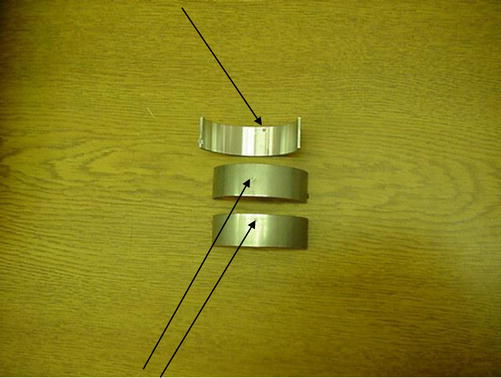
Figure D-2. Photograph of Connecting-Rod Bearing FM
It is extremely important to walk the faulty operation and look for any condition that could contribute to a problem. In this case, we observed that there was a prevalence of chips beneath the piston-assembly station that had accumulated during the manufacturing cycle. The foreign material was later identified as connecting rod flakes that had not been removed from the rods after they had been machined. See results of foreign material in Figure D-3.
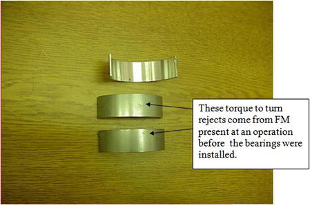
Figure D-3. Photograph of Torque-to-Turn Bearing Rejects
These flakes were due to inadequate DFMEA, PFMEA, testing, and lack of changes to the control plan, as well as the elimination of a cleaning operation by the supplier without permission after the rod design had been changed. The fact that these parts passed the final inspection indicated a failure in the inspection procedures, something that also had to be revised at the supplier.
Figure D-4 shows the old piston connecting-rod assembly on the left and the newly revised piston connecting-rod assembly on the right. The replacement assembly has sloped shoulders, whereas the old one had flat shoulders. This difference in slope allowed the automatic drills in machining to displace by bending a sliver of material on the sloped surface. It had been previously removed when the machining was performed on the flat surface assembly rod. This illustrates the importance that any change, no matter how small, must be reviewed and approved before it can be made.
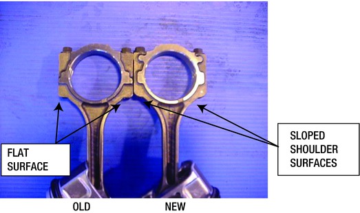
Figure D-4. Photograph of Connecting Rod Modification
During the investigation phase, it was determined that the piston area for the number 5 piston was providing the most problems because of foreign material. The photographs that follow (Figures D-5 and D-6) show the location of the pistons within the assembly-and-transfer fixture after they were unbolted and rotated. This fixture transferred the pistons to an assembler mechanism where they were provided with bearing half rounds before assembly into the engines. This operation was later found to allow some of the flakes to fall into the bearings and the engine bore upon piston assembly.
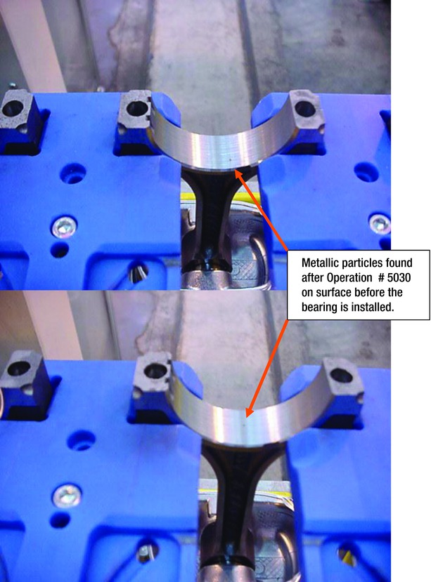
Figure D-5. Piston Assembly Pre-Positioning Fixture
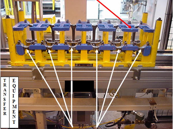
Figure D-6. Photograph of Six Pistons in Assembly and Transfer Fixture
In the evaluation period, we had walked past the piston transfer fixture numerous times without noticing the foreign material (FM) that was under the machine. Only upon walking the floor twice in one day did we notice the FM. During the first walkthrough, the floor had been swept clean; later that same afternoon we noticed the FM under the station.
The pistons were placed into the fixture in sequence as shown, which represented the placement into the engine cavity bore:
Bore:           #6         #4          #2          #1          #3         #5
Place Order:   1st        2nd         3rd         4th         5th       Last
The biggest foreign material problem was evident from the piston stuffed into bore 5. FM chunks were found at the station before the bearing assembly operation.
There was no FM observed on the half round area on the lower section of the connecting rods before and/or after the bearing was installed into the half round. Even after piston rotation, there was no FM on the bearing in the lower part of the pallet. This was observable up to and including the next sequence operation, which was the insertion of the pistons into the engines. From there, the engines were tested and either passed or were rejected for rework.
Figure D-7 shows foreign material particles removed from the floor under the transfer station.
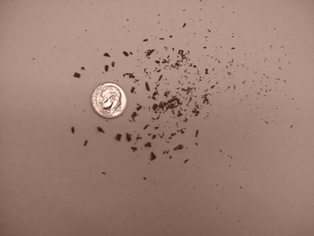
Figure D-7. Photograph of Particulate Found at the Station
We believed this particulate to be powdered metal shavings from the connecting rods. We later proved that this was correct; the newly designed pistons that had a sloped shoulder did not have all the particulate removed after their primary machining operation. The engine plant piston supplier neglected to continue the approved process that had been agreed upon and certified when the contract had been approved. Again, you must scrutinize your suppliers, as they will often attempt to reduce internal costs without prior customer approval.
Many of the methods used to generate clues and to solve problems are apparent in this example. It is not uncommon to find that there may be two or more separate conditions that affect a process and create a flaw. Moreover, whenever materials, processes, or suppliers change, it becomes possible for a negative effect to be produced. Simply walking the problem area, defining the problem, providing photographs, and making visual inspections will generate enough clues to get the investigation started.