

Cracked-or-Broken Example
This appendix contains more examples of cracked-or-broken problems that we have been encountered in various industries. These examples are intended to provide you with other perspectives that you can use when you’re evaluating cracked or broken components. It also explains why the cracked-or-broken check sheet included here should be used to help generate clues.
You can use the sheet shown in Figure C-1 when you’re evaluating a damaged or broken component in conjunction with a concept diagram. The sheet is self-explanatory; questions relate to the strength of the component and the conditions that may have acted upon the component to cause failure. As you gain experience with these forms and methods, you will recognize other valuable considerations applicable to your products. You should save these recognized considerations or items of interest and incorporate them into your most useful sheets.
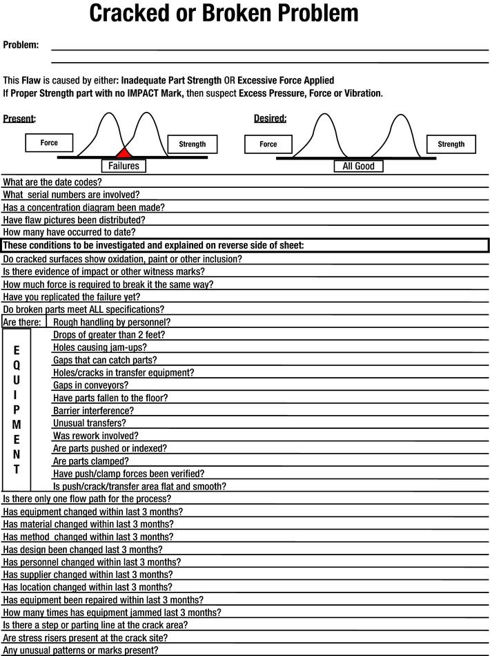
Figure C-1. Cracked or Broken Criteria
The two concept diagrams shown in Figures C-2 and C-3 can provide you with a better understanding of conditions that lead to cracked or broken components. You can use these conditions to analyze similar problems.
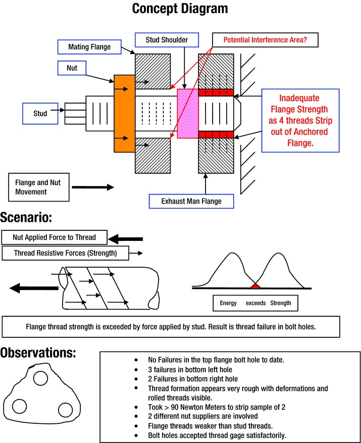
Figure C-2. Stripped Flange Bolt Holes
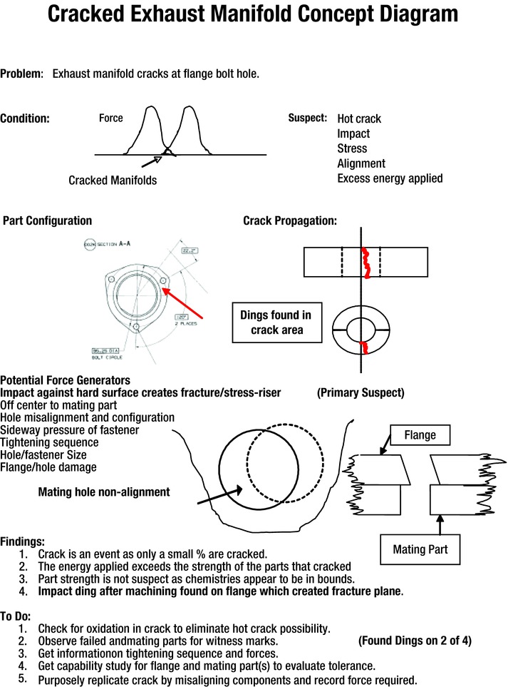
Figure C-3. Cracked Exhaust Manifold Example
The stripped flange bolt problem can help you visualize the forces applied in the assembly of components, as well as any reactive forces that may be present. Figure C-2 shows that there is a potential interference area between the stud shoulder and the mating flange during assembly. This potential interference area is caused when the nut being tightened forces the mating flange into the stud shoulder. The exhaust manifold flange, which was not of proper strength, contained weakened threaded material that was not to specifications. The sketch in Figure C-2 shows where the four threads stripped.
This is further explained in the lower sketches in Figure C-2, which show that the applied force was greater than the resultant resistant forces of the individual threads; these are illustrated by the arrows and force vectors. This imbalance resulted in thread failure. The lower comment box shows examples of the types of observations that can be made in such studies.
The next example, shown in Figure C-3, describes the causes to consider when a component breaks during assembly. If the component material is to specification, you must evaluate other considerations. Hot cracks, impacts, stresses, alignment issues, or excess energy applied are the paramount considerations. In this case, alignment problems were cited. The flange hole was not properly aligned with the mating part, which caused excessive stress. Result: failure.
It should be clear by now that you can identify the causes of cracked or broken components using the methods described in this book. These methods enable you to use a simple concept sheet as a very effective investigative tool.