One of the most critical aspects of managing your VMware ESXi environment is security. ESXi was designed with a focus on providing a secure and safe platform to host your virtual machines. Security is a very complex topic and not something that can be easily summarized with a single chapter. You have already seen a number of topics related to security discussed in earlier chapters, and that will continue to be the case for the remainder of this book. When considering the security of your vSphere environment, you should examine several components, including your ESXi hosts, vCenter Server, network setup, storage access, and virtual machine setup. This chapter will review some of the tools and techniques that are available to secure your environment.
The topics discussed in this chapter include the following:
ESXi architecture and security features
Network protocols and ports for ESXi
Protecting your vSphere environment with firewalls
Enabling ESXi Lockdown Mode
Configuring authentication and users
Replacing ESXi’s self-signed SSL certificates
Configuring IPv6 and IPSec
Securing network storage
Securing virtual networking
Security and clustering
Isolating virtual machine environments
There are two classifications of hypervisors. With a Type 2 or hosted hypervisor, a traditional operating system is installed directly onto the server hardware, and the hypervisor represents a distinct second layer of software. The guest operating systems running in the virtual machines then represent a third layer of software. Examples of Type 2 hypervisors include VMware Server and VMware Workstation. With a Type 1 or bare metal hypervisor, the first software layer is the hypervisor. Examples of Type 1 hypervisors include VMware ESXi, VMware ESX, and Microsoft Hyper-V. The hypervisor directly controls all hardware in the server without the performance impedance of running through a host operating system.
Bare metal hypervisors also enjoy a significant security advantage over Type 2 hypervisors in that they do not come with the security risks of a general operating system. Rather than also needing to provide network services such as file and print services, the hypervisor is designed exclusively for the purpose of running virtual machines. However, even within the available choices of Type 1 hypervisors, there are some significant differences in hypervisor architecture. Some hypervisors such as Hyper-V use a virtualized parent partition to manage the hypervisor layer. This adds another layer of security concern and opens the host to additional security risks that may be embedded within the operating system running in the parent partition. ESXi was designed to approach an embedded firmware model that does not include a management partition and the security risks inherent with that model.
The security focus in the design of ESXi is on the following three separate components: the VMkernel, virtual machines, and the virtual networking layer.
The VMkernel represents the heart of ESXi, and it is the component of ESXi that provides a virtual interface to the virtual machines that run on your hosts. The VMkernel manages interaction with the host’s hardware devices, allocates memory to different processes, and schedules central processing unit (CPU) access. The VMkernel was designed for no other purpose than to run virtual machines, and the API that it exposes is limited to that purpose.
The VMkernel includes the following features to provide a secure environment for virtual machines: kernel module integrity, memory hardening, and the Trusted Platform Module (TPM).
Kernel module integrity consists of digital and module signing. Digital signing is used to ensure the authenticity of integrity of applications, drivers, and modules as they are loaded by the VMkernel. Module signing enables ESXi to identify the developers of applications, drivers, and modules and to verify whether VMware has approved those components.
The purpose of memory hardening is to use memory techniques and modern processor capabilities to protect the system from common buffer overflow attacks that can be used to exploit weaknesses in running code. ESXi uses Address Space Layout Randomization (ASLR) to load the VMkernel, user-mode applications, and executable components such as drivers and libraries at random and unpredictable memory locations. ESXi also takes advantage of Intel XD (eXecute Disable) and AMD NX (No eXecute) support to mark writable areas of memory as nonexecutable.
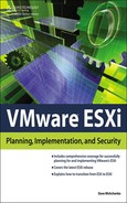
TPM provides platform verification during the boot process as well as cryptographic key storage and protection. TPM requires that the server have a special hardware chip installed that contains a unique Remote Supervisor Adapter (RSA) key. Ensure that TPM is properly enabled in the Basic Input/Output System (BIOS) of the host. During booting, ESXi measures the VMkernel using the TPM and stores the value in one of its platform configuration registers. TPM measurements are propagated to vCenter Server when the ESXi host has been added to vCenter, and the measurements can be obtained by third-party agents using the vCenter Server application programming interface (API). In addition to enabling TPM in the BIOS, enable the Misc.enableTboot option shown in Figure 7.1.
Virtual machines are software containers that encapsulate the necessary components for a guest operating system (OS) to execute. When a guest OS is being installed, it sees a CPU, memory, the network card, and the disk in the same way that it would on a physical host. But these resources are virtualized and thus the guest operating system does not have direct control of the hardware resources in the ESXi host. This design effectively isolates virtual machines from one another. In the case of an OS running on a physical server, an OS failure is isolated to a server’s hardware and does not impact other hosts on the network directly. With a virtual machine, it is critical that a failure in the OS be limited to just the virtual machine and that the failure have no impact on the ESXi host or other virtual machines running on that host. The security design of ESXi virtual machines provides this protection.
This protection also ensures that one virtual machine cannot arbitrarily breach the security of another virtual machine or the host. A user operating in one virtual machine will not be able to take advantage of the fact that other operating systems are running virtual on the same host to circumvent their security unless the user has been granted specific privileges on the ESXi host. All access to hardware on the host is made through the VMkernel, which ensures that the environments are kept isolated and that one virtual machine will not be able to control or circumvent processes within another virtual machine.
Virtual machines require the ability to communicate with other virtual machines and physical hosts, and this is done through a virtual network interface card (NIC). A virtual network card (vmnic) is connected to a virtual switch (vSwitch), which can then provide access to your network when the vSwitch is linked to physical adapters in your ESXi host. A virtual machine with a vmnic is not able to bypass the security of your vSwitch design. If the vSwitch to which a virtual machine is connected has not been linked to your network, the virtual machine will effectively be isolated and only able to communicate with other virtual machines on the same vSwitch. Likewise, two virtual machines on different vSwitches on the same host will not be able to communicate with each other unless both vSwitches have been configured to be linked to your physical network through the network adapters in your ESXi host.
To protect virtual machines further, you should consider the use of limits, shares, and resource reservations. This topic was discussed briefly in Chapter 3, “Management Tools.” By default, ESXi imposes a form of resource reservation to ensure that the resources of the host are divided equally among the virtual machines running on the host. If a virtual machine on the host were to be compromised by a denial-of-service (DoS) attack, the other virtual machines would be partially isolated from the resource drain caused by the DoS. You could further limit the impact of a problem virtual machine by setting specific reservation and limits. With a reservation, you ensure that a virtual machine has a guaranteed quantity of a specific resource and you could also use a limit to ensure that a virtual machine would not consume excessive hardware resources. For low-resource virtual machines that are accessible to the Internet, you may consider lowering the CPU shares or setting a CPU limit for the virtual machines. In the case of a compromise, the virtual machine would have limited CPU resources to attack other hosts and consume fewer CPU resources on the host.
The virtual networking layer includes both the vmnics used in virtual machines and vSwitches. The networking layer provides network connectivity between virtual machines and other hosts on your network. The networking layer is not just limited to providing network service to virtual machines; ESXi uses it for management, communication with other ESXi hosts and vCenter Server, Internet Small Computer System Interface (iSCSI), and network attached storage (NAS).
With your implementation of ESXi, you need to spend some time carefully planning your network design to ensure that virtual machines are properly placed in the correct vSwitches and to ensure that virtual machines and other ESXi network components are properly isolated and protected from each other. ESXi supports 802.1q virtual local area networks (VLANs), which you can use to protect your virtual machines further and to isolate virtual machines and other ESXi network services even within the same vSwitch.
With the isolation that the virtual networking layer can provide, you can securely deploy ESXi to provide access to virtual machines that need to be placed into a demilitarized zone (DMZ) without compromising the security for your other virtual machines and, as important, without exposing management access to ESXi within the DMZ. DMZ virtual machines are typically exposed to the Internet and represent the virtual machines in your environment that are most open to attack by intruders. If you consider the default installation of ESXi, a single vSwitch is created with a virtual machine port group and a management port. If you want to place virtual machines within your DMZ, you don’t want to unplug the network port linked to the management vSwitch and connect that to the DMZ. Rather, create a new vSwitch with a second network port on the host, which would be connected to the physical switch of your DMZ. On this second vSwitch, add a new virtual machine port group for the DMZ. The result would be two isolated vSwitches, and virtual machines on both would not be able to communicate to virtual machines on the other without routing their traffic through an established firewall on your network. Further, no management interface for ESXi would be exposed in the DMZ, and given what you’ve seen with virtual machine isolation, the ESXi host would be safe from attack from a compromised DMZ virtual machine.
As you add physical NIC ports to your host, you could also create additional vSwitches to isolate network traffic for other virtual machines on different network segments or to isolate ESXi storage network traffic. For additional reading on vSwitch design, an excellent online resource is http://kensvirtualreality.wordpress.com/2009/03/29/the-great-vswitch-debate-part-1/, and the ESXi Configuration Guide contains a best practice guide for various network scenarios.
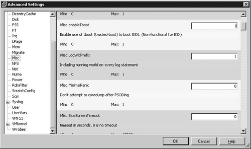
In some scenarios, you may have a limited number of NIC ports on your ESXi host and with the emergence of 10GB networking, you may be consolidating the virtual networking layer onto fewer NICs. In such a case, you can configure your vSwitches with multiple port groups for various network services and then isolate each within the vSwitch with VLANs. The sample shown in Figure 7.2 has a single vSwitch connected to two physical NIC ports in the host. A number of different network services are provided in this scenario, including the management interface for ESX, the network storage interface for ESXi, and virtual machines hosted in a DMZ. Those are obviously not types of traffic that you would want to mix on the same network segment, as compromising a DMZ virtual machine would open the rest of your network infrastructure to attack. In this case, the traffic types are isolated through the use of VLANs.
You may be wondering about network communication between virtual machines on the same vSwitch. If the virtual machines are separated with VLANs, network traffic between the two virtual machines must leave the vSwitch and will be routed between the two subnets through an existing router or firewall. But for two virtual machines on the same VLAN and vSwitch, the network traffic that passes between the virtual machines receives no protection. You can consider deploying firewalls within your virtual machines or may consider employing virtual firewalls. VMware vShield App is an example of a hypervisor-level firewall and provides connection control based on network, application port, protocol type, and application type. This product is discussed later in this chapter.
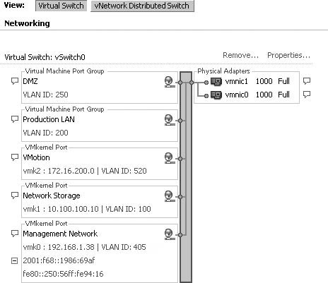
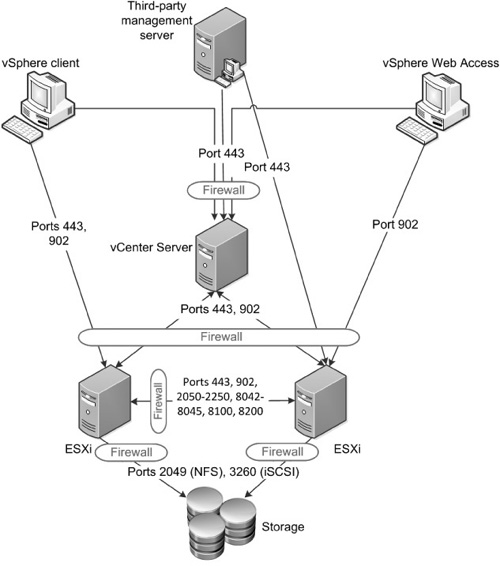
Network access to VMware ESXi, vCenter Server, and other components in your vSphere deployment is made over predetermined Transmission Control Protocol (TCP) and User Datagram Protocol (UDP) ports. As you explore employing firewalls to protect your infrastructure, identify which ports will have to be opened and how the components of your infrastructure will interact. Figure 7.3 displays the network ports used in a typical vSphere implementation.
vSphere client access is made over TCP port 443 and that can be directed at the vCenter Server or directly to a host if you are managing the host directly. But you should note that the vSphere client also connects to the ESXi hosts on port 902. This network traffic is for virtual machine console access. In the case of using vSphere Web Access, the Web interface is provided by vCenter Server, as this component is not included with ESXi. However, when a vSphere Web Access session opens a virtual machine console session, this connection is made directly to the ESXi, as is the case with vSphere client.
Communication between vCenter Server and the ESXi hosts is also made over ports 443 and 902. You will note that High Availability (HA) traffic is limited to the ESXi hosts only. Once you have configured HA on your hosts, which you’ll learn how to do later in this chapter, it is communication among the ESXi hosts that determines HA actions, and the vCenter host is not involved. Your ESXi hosts will also communicate with network storage and, potentially, third-party management tools.
The common ports are summarized in Table 7.1. When configuring your firewalls, you will need to distinguish between TCP and UDP traffic and you should note that in most cases, traffic is unidirectional. The table is not meant to provide an exhaustive list of ports, nor does Figure 7.3 include all the ports that your vSphere environment will use. You can find an exhaustive list in this VMware Knowledge Base article: http://kb.vmware.com/kb/1012382.
Table 7.1. Network Ports for a Typical vSphere Implementation
TCP | UDP | ||||
|---|---|---|---|---|---|
Port | Description | Incoming | Outgoing | Incoming | Outgoing |
80 | HTTP access Port 80 is redirected to the HTTPS landing page Web Services for Management (WS-Management) | X | |||
123 | NTP client | X | |||
389, 636. 1024+ | Communication between vCenter Server hosts for linked mode | X | X | ||
427 | Service Location Protocol used by the CIM client to find CIM servers | X | X | ||
443 | HTTPS access vCenter Server access to ESXi SSL Web port vSphere client access to vCenter Server vSphere client access to ESXi vSphere client access to vSphere Update Manager vSphere Converter access to vCenter Server WS-Management | X | |||
902 | ESXi to ESXi for migration and provisioning Authentication traffic for ESXi and remote console traffic vSphere client access to virtual machine consoles Heartbeat connection from ESXi to vCenter Server (UDP) | X | X | ||
1433 | vCenter Server and Update Manager access to SQL Server | X | |||
1521, 1526 | vCenter Server and Update Manager access to Oracle Database Server | X | |||
2049 | VMkernel port to NFS storage | X | X | ||
2050-2250 | Traffic for High Availability between ESXi hosts | X | X | X | |
3260 | VMkernel port to iSCSI storage | X | |||
5900-5943 | RFB protocol used by management tools such as VNC | X | X | ||
5989 | CIM XML transactions over HTTPS | X | X | ||
8000 | Requests for vMotion | X | X | ||
8042-8045 | Traffic for High Availability between ESXi hosts | X | X | X | |
8100, 8200 | Traffic for Fault Tolerance between ESXi hosts | X | X | X | |
Chapter 3 discussed syslogging. If you implement that, the ESXi hosts will be communicating with the syslog receiver over UDP port 514. Likewise, if you’re using a third-party tool to monitor the hardware in your ESXi host with Common Information Model (CIM), the management server requires access on TCP port 443. If you enable e-mail alerting in vCenter Server, the server communicates with your mail server on TCP port 25. Chapter 4, “Installation Options,” discussed the process for using a Preboot Execution Environment (PXE) server. If you plan to deploy servers via PXE, you need to open ports to the PXE server, the Dynamic Host Configuration Protocol (DHCP) server, and, optionally, a Web or Network File System (NFS) server if you’re using scripted installations and a media depot. If you add VMware Data Recovery and Update Manager, they require another set of network ports. That includes both ports between the vSphere client and the server components of those products, between the ESXi hosts and those same server components, and between the server components and vCenter Server.
Once you have established a good understanding of the network access that various components of your vSphere environment will require, you will be able to plan your firewall deployment to protect those components. Earlier in this chapter, the importance of isolating various types of traffic was discussed. A DMZ virtual machine should have no access, for example, to your storage system. But it is important to consider any host as a potential threat to your vSphere infrastructure. Numerous studies point to insiders as the greater risk to network security than external hackers, and even a virus or instance of malware inadvertently introduced into your environment will pose a risk to any systems it can access.
Firewalls are used to control access to hosts and other network devices by closing all network ports and paths except those specifically configured for the network to function properly. ESXi does not include a firewall because it runs a limited set of well-known services and does not allow the addition of further services. With this design, the need to run a built-in firewall, as is the case with VMware ESX, is significantly reduced in ESXi.
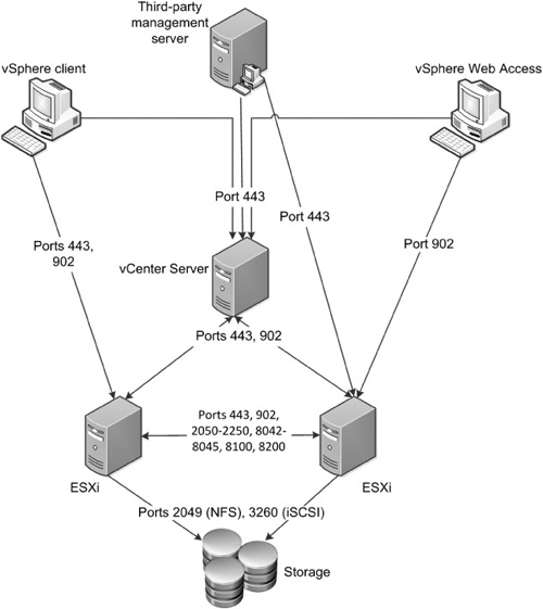
Your deployment of firewalls to protect your vSphere deployment will depend on your security needs. Figure 7.4 shows a number of potential locations for firewalls in a typical vSphere deployment. In this example, all client traffic to the vCenter Server is routed through a firewall. This includes any management applications that will interact with vCenter Server. If you plan to provide remote console access to the virtual machines, you will further have to open your firewall to allow direct access from the client computers to the ESXi hosts for TCP port 902.
You may also consider a firewall between your vCenter Server host and your ESXi hosts. There are a limited number of ports that you have to open for this, but you should keep in mind that modules such as Update Manager and Data Recovery will require additional ports to be open. The sample configuration also has firewall protection between the ESXi hosts and storage devices. Between hosts, the traffic can be considered trusted, but if you have stringent security requirements and are concerned about a breach of your ESXi hosts, you can secure the network for HA, vMotion, Fault Tolerance, and other interhost communication. Given that the vCenter Server and vSphere client do not require access to the network used for interhost communication, you may consider physically isolating the network that is used for that traffic. The same consideration can be given to the network used to connect your ESXi hosts to your storage devices.
Caution
For some implementations, administrators are choosing to use a software initiator within a virtual machine to access iSCSI storage rather than relying on vSphere hosts to access the iSCSI logical unit numbers (LUNs) directly. In some cases, this is due to a performance improvement, whereas in others it is to overcome the 2TB LUN limitation of vSphere. If you choose to provide iSCSI storage access to your virtual machines, you should carefully consider the security implications and design your security to protect both your iSCSI servers and your ESXi host from an attack launched from a compromised virtual machine that has access to the storage network.
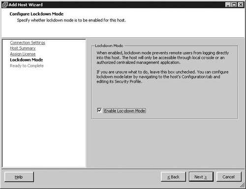
To enhance the security of your VMware ESXi hosts, you can enable Lockdown Mode when adding a host to your vCenter Server or after the vSphere client or the Direct Console User Interface (DCUI). Lockdown Mode restricts which accounts are able to manage the host via the following host services: the vSphere API, which is used by the vSphere Client, the vCLI, and other API clients; CIM; Tech Support Mode; and the DCUI. After you enable Lockdown Mode, no account other than vpxuser will have authentication permission or be able to perform operations directly on the host. This requires that you manage your ESXi host using vCenter Server rather than connecting directly with your management tools.
Caution
With ESXi 4.1, all accounts, regardless of privileges, are prevented from making direct host connections with the vSphere client, the vCLI, PowerCLI, or other management tools. This includes both local accounts on the ESXi host and Active Directory (AD) accounts that have been granted permissions directly on the host. Only connections made via vCenter Server, which uses the vpxuser account to connect, are allowed. This may impact other software or management tools that you want to use with ESXi. The root login and other accounts with root privileges may still log in at the DCUI to perform management tasks including disabling Lockdown Mode. This may be necessary in an emergency situation where your vCenter Server is not available.
When you enable Lockdown Mode, this does not affect the services running on the host. Local Tech Support Mode, Remote Tech Support Mode (SSH), and the DCUI services can still be started or stopped independent of Lockdown Mode. Login with either Local or Remote Tech Support Mode will not be possible when Lockdown Mode is enabled. In Local Tech Support Mode, you will receive the error Login Incorrect, and with Remote Tech Support Mode, you will receive the error Access Denied.
Lockdown Mode can be enabled when you add a host to vCenter Server, as shown in Figure 7.5. You can also enable and disable Lockdown Mode after a host has been added to vCenter Server using the vSphere client or the DCUI.
To enable Lockdown Mode on a host that has already been added to vCenter Server, you can use the following process:
Log in to your vCenter Server with the vSphere client.
Select the host in the inventory panel for which you wish to enable Lockdown Mode.
Select the Configuration tab and click Security Profile.
Click the Edit link next to Lockdown Mode.
Select Enable Lockdown Mode on the Lockdown Mode dialog box.
Click OK to complete the change.
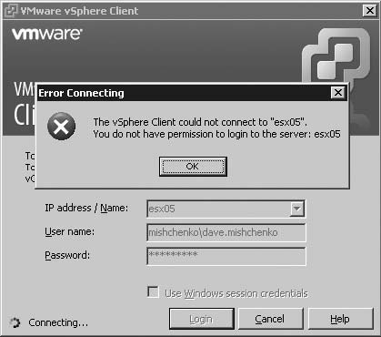
The host enters Lockdown Mode immediately. Any connection made directly to the host via the vSphere API terminates after a short period. Existing Local and Remote Tech Support sessions are not closed automatically. If you attempt to log in directly with the vSphere client after Lockdown Mode is enabled, you will receive the error shown in Figure 7.6.
Tip
To audit the disabling of Lockdown Mode and access Tech Support Mode, see the section “Auditing Tech Support Mode” in Chapter 11, “Under the Hood with the ESXi Tech Support Mode.”
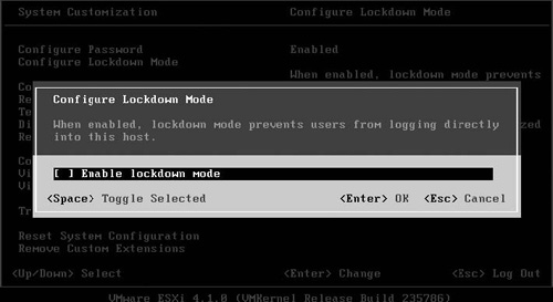
You can also enable and disable Lockdown Mode with the DCUI. This may be necessary if your host is unable to communicate with vCenter Server and you need to connect with the vSphere client or other tools to correct the problem. The following process can be used to disable Lock-down Mode with the DCUI.
Access the DCUI for your ESXi locally at the console or via a remote management card.
Log in with an account such as root that has access to log in to the DCUI.
Select Configure Lockdown Mode on the System Customization menu and press Enter.
On the Configure Lockdown Mode dialog box, press the spacebar to uncheck the option Enable Lockdown Mode, as shown in Figure 7.7.
Press Enter to complete the change.
Caution
It is possible to deny access to the DCUI by stopping the associated service for it. This is possible on the Security Profile screen or with Host Profiles. If the DCUI service is stopped, you cannot log in to the DCUI. This may present a problem should you need to disable Lockdown Mode on a host to allow for a direct connection for troubleshooting purposes. Disabling the DCUI may be appropriate for your ESXi implementation. For example, if you have a host in a remote office, you may not be able to control physical access to that host. However, troubleshooting options may be limited if the host is not accessible via vCenter Server and you will not be able to use the DCUI.
At this point, you will not be able to manage Lockdown Mode as part of the vCLI or PowerCLI, but you will be able to query the lockdown setting with PowerCLI. The following script provides a list of all ESXi hosts that are part of your vCenter Server and displays the lockdown status for the hosts. The Where { $_.Version -match "ESXi"} clause ensures that vSphere ESX hosts are not included in the output from the script.
Get-View -ViewType HostSystem | Select Name,
@{N="Version";E={$_.Summary.Config.Product.Name}},
@{N="State";E={$_.Runtime.ConnectionState}},
@{N="LockedMode";E={$_.Config.AdminDisabled}} | Where { $_.Version -match "ESXi"}

Name              Version                 State              LockedMode
----                -------               -----              ----------
esx01.mishchenko… VMware ESXi              connected             False
esx05.mishchenko… VMware ESXi          notResponding             False
esx02.mishchenko… VMware ESXi              connected             False
The ability to enable or disable Lockdown Mode is available for PowerCLI as part of the virtual interface (VI) Toolkit for Windows Community Extensions project, which is available at http://vitoolkitextensions.codeplex.com/. The Set-TkeVMHostLockdown cmdlet is included, which allows you to enable Lockdown Mode with the following command:
Get-VMHost | Set-TkeVMHostLockdown $True
You can disable Lockdown Mode with this command:
Get-VMHost | Set-TkeVMHostLockdown $False
With the default installations of VMware ESXi and vCenter Server, a fairly basic access structure is put in place. When connecting directly to your ESXi host with the vSphere client, you log in with the root account. If your host has been configured for AD Integration, as shown in Chapter 6, “System Monitoring and Management,” accounts that are part of the AD group ESX Admins will be also able to log in to the host directly. In both cases, you will have full administrative rights on the host. With vCenter Server members of the local administrator, groups on the host will have full control of your vCenter structure. When adding a host to vCenter, the account vpxuser will be created on the host and granted the Administrator role at the host level. All interaction between your vCenter Server and ESXi hosts will be made with that user account.
It is unlikely that this default security implementation will be sufficient for your needs, so you will need to assign additional access to your hosts. VMware ESXi and vCenter Server will use a combination of user account, password, and permissions to determine the access for a user and the authorization that the user has to perform certain actions. Both ESXi and vCenter Server maintain separate user and access lists, but the process of managing users and permissions is the same with both. The next section will discuss the concepts and steps to maintain permissions on a standalone ESXi host. The following section in this chapter will review the processes for vCenter Server and highlight the differences and improvements over managing permissions on a standalone host.
Each VMware ESXi host that you deploy will maintain its own list of users, groups, roles, and permissions. To view the default accounts on your host, select the Home > Inventory > Inventory view. Select the Local Users & Groups tab and click Users. You will see the list shown in Table 7.2, and as you will note, it is a much shorter list than with ESX due to the removal of the Linux-based Service Console in ESXi. ESXi likewise has far fewer locally defined groups than ESX. These groups include root, daemon, nfsnobody, nobody, tty, users, and vimuser.
Table 7.2. The Default ESXi User Accounts
User | Name | Description |
|---|---|---|
root | Administrator | The root user has full administrative rights on the host. By default, this account will have a blank password and should be set after the installation. This account will be used during the process of adding your ESXi host to vCenter Server. |
dcui | DCUI User | The DCUI user is granted the Administrator role at the host level on your ESXi host. The user’s primary role is to configure hosts for Lockdown Mode from the direct console. The user is used as the agent for the DCUI and should not be modified or used to log in to your ESXi hosts. |
nfsnobody | Anonymous NFS User | This is the system account used to access NFS datastores. |
vimuser | vimuser | Vimuser was provided with ESX Server 3.i to allow you to configure a delegate user. This could be necessary when connecting to an NFS server with root squashing enabled. This was experimentally supported and is not available with VMware ESXi 4.1. |
vpxuser | VMware vCenter administration account | This account is used by vCenter Server to issue commands to your ESXi host regardless of the end user that is connected to vCenter Server. This account is granted the Administrator role at the host level. This account will be discussed further in the following section. |
Caution
The vpxuser and dcui users should not be altered in any way. Doing so can create problems when you try to manage the host with vCenter Server or with the DCUI.
To create a new user, you can use the following process:
Start the vSphere client and log in directly to the ESXi host.
From the Home screen, select the Inventory icon to view your ESXi host. You can also use the shortcut Crtl+Shift+H to switch to the Inventory view.
Select the ESXi host in the inventory tree and click the Local Users & Groups tab.
Ensure that the Users view is selected, and then right-click on a blank space in the Users view and select Add.
On the Add New User dialog box, you need to enter a login name and password. It is optional to enter a Username or UID (unique identifier). When the account is created, the next UID will be assigned to the account. You will also notice that there is no option to grant shell access as you would find when creating a local user on an ESX host.
You can optionally add to the user any groups that exist by default or that you have created.
Click OK to complete the creation of the new user account.
Merely adding an account will be insufficient to enable a user to log in to your ESXi host. The account must be granted a role on your ESXi host. Roles are a collection of privileges; when you assign user or group permissions to an object on your ESXi host, you’ll grant the user or group a specific role to an object, and that role will define which privileges are granted to the object.
On an ESXi host, there are three predefined roles that cannot be modified or deleted. These roles can be used to assign privileges to your user or as models for more refined roles. Table 7.3 lists the default roles that you will find on your ESXi host.
Table 7.3. Default Roles on an ESXi Host
Role | Description |
|---|---|
Administrator | This role has all privileges for all object types. This role allows a user or group to manage any object on the host and can be used to manage roles and permissions for other users. By default, the root login will have the role assigned at the host level. The same will be the case with the dcui user and vpxuser if the host has been added to vCenter Server. If you have enabled AD Integration, the AD group ESX Admins will also be assigned this role at the host level. |
Read Only | This role allows a user to see all details and the state of the object to which the permission has been assigned. The user will not be able to perform any actions on the menus or toolbars nor access the console of a virtual machine. |
No Access | The No Access role includes no privileges and can be used to deny access to an object. When you are granting permissions, the privileges in the role used are propagated to child objects by default. You can use the No Access role to deny a user access to an object when that user has been granted permissions to a parent object. |
Use the following steps to create a new role:
Start the vSphere client and log in directly to the ESXi host.
From the Home screen, select the Role icon to view the roles defined on your host. You can also use the shortcut Crtl+Shift+R to switch to the Roles view.
Click the Add Role button.
On the Add New Role dialog box, enter a name for the new role. Then select the privileges that you wish to assign to the role. Figure 7.8 shows some of the privileges appropriate for a virtual machine administrator role.
Click OK to complete creating the new role.
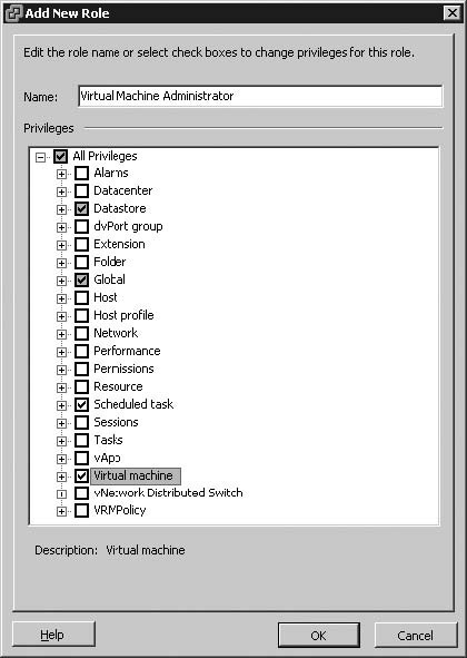
When you create a new role, you will observe that there are a significant number of individual privileges that can be assigned to a role. When you select an individual privilege, a short description is shown for it. You can also refer to The vSphere Datacenter Administration Guide for a list of required privileges for common tasks.
The final step in granting permissions to a user or group consists of granting that user or group a role for an inventory object. For a standalone ESXi host, you can assign permissions to the host, resource pools, or virtual machines. By default, the root and dcui accounts will have the administrator role on all objects on the host. The permission for these accounts is granted at the host level with the Propagate to Child Objects option enabled so that the accounts will have full control of all objects created on the host. When the host is added to vCenter Server, the vpxuser is granted the Administrator role at the host level as well. This is also the case for the AD group ESX Admins when you configure AD Integration.
To assign permissions to an object on your ESXi host, follow these steps:
Start the vSphere client and log in directly to the ESXi host.
From the Home screen, select the Inventory icon to view your host.
Select the object to which you want to grant a new permission and select the Permission tab to view the existing permissions for the object.
Right-click on the object and select Add Permission.
Click Add on the Assign Permissions dialog box to select the user or group.
The Select Users and Group dialog box will open. If you have AD Integration enabled, you can select your AD domain in the Domain drop-down box to select an AD user or group. Once you have selected your user or group, click OK to return to the Assign Permissions dialog box.
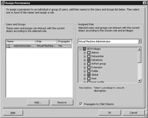
Select the role for the user or group as shown in Figure 7.9.
Click OK to complete assigning the permission.
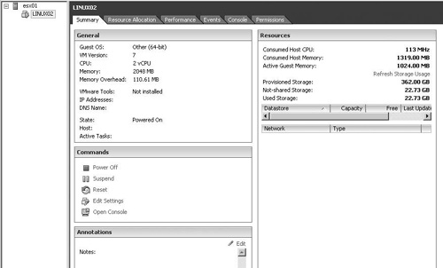
For a user who has limited permissions on your host, the vSphere client will display only the objects for which the user has permissions assigned. In Figure 7.10, the vSphere client displays only the ESXi host and the specific virtual machine for which the user has been assigned a virtual machine administrator type role. If the user selects the host object, no information will be displayed, and he or she will see the error message You do not have the permissions to access this object. If the user right-clicks on the host, all options will be grayed out. The user will be able to control the virtual machine, but not perform any actions that require host permissions. For example, Figure 7.10 shows no datastore listed, as the required permissions have not been granted. Likewise, the user is not able to modify the permissions for the virtual machine. The Events tab and the Recent Tasks pane will filter information based on the user’s permissions. If a user just has permission to a virtual machine, he or she will not see tasks and events related to the host or other virtual machines.
If you need to assign permissions to a number of virtual machines on your standalone host, you may find it cumbersome to manage permissions on each virtual machine. You can use a resource pool to create a folder for your virtual machines and then just assign permissions on the resource pool, which will propagate to each virtual machine. Use the following steps to create a resource pool and to move your virtual machines to it:
Start the vSphere client and log in directly to the ESXi host.
From the Home screen, select the Inventory icon to view your ESXi host. You can also use the shortcut Crtl+Shift+H to switch to the Inventory view.
Right-click on your host and select New Resource Pool.
Enter a name for the resource pool. You can set resource limits and reservations, but in this case, doing so is not required, as you’re only looking to organize your virtual machines into groups.
Click OK to create the resource pool.
To move virtual machines to the resource pool, simply select the virtual machines in the navigation tree and drag and drop them into the resource pool.
Right-click on the resource pool and select Add Permissions.
Use the preceding process to add permissions to the resource pool. When assigning permissions, ensure that the Propagate to Child Objects option is enabled.
Once the resource pool has been set up with the appropriate virtual machines and permissions have been set for a user to manage the virtual machines in that resource pool, the user will log in with the vSphere client and be able to view only the resource pool and virtual machines in that resource pool. The user’s capabilities will be the same as described previously when a user was set up with permissions for a single virtual machine and not the host, as shown in Figure 7.10.
When you move virtual machines, any permissions assigned to them will remain in place after the object is moved into a resource pool. If a virtual machine is assigned the No Access role to a specific user, the user will not have access to or be able to see the virtual machine, regardless of the permissions that were set on the resource pool.
Tip
With both VMware ESXi and vCenter Server, it is possible to assign permissions to both user and groups. As a best practice, it is recommended to use groups over users to assign permissions. This will not only make managing permissions easier but reduce the risk of an individual user maintaining permissions on the host when that is no longer part of the user’s role.
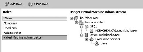
After you have established your permissions, you may find the need to review, update, or remove permissions. In the vSphere client, select the Roles view to view the currently configured roles. If you select a role, you will see whether the role is unused and the objects to which the role is assigned. In Figure 7.11, you can see that the Virtual Machine Administrator role is assigned to the XP01 virtual machine and the Production Servers resource pool. A green arrow on the user or group indicates that the permission has been set with the Propagate to Child Objects option enabled. To change the privileges for the role, simply right-click, and then select Edit Role. You can also remove the role by right-clicking and selecting Remove. If the role is currently in use, you will be given the choice to remove role assignments or to reassign the affected users to another role.
To view permissions for an object in the vSphere client, you select the object, which in the case of a standalone host will be the host, a resource pool, or virtual machine, and then select the Permissions tab. You will be able to view the permissions set on that object and any permissions set on parent objects that have been propagated to the object you are viewing. To remove a permission, right-click on the entry and select Delete. To change the role for a user or group, right-click, and then select Properties. You can then select the new role to use and also change the Propagate to Child Objects option.
Managing permissions with vCenter Server follows the same process as with a standalone ESXi host. Users or groups are assigned a specific role to an object in vCenter Server. vCenter Server does not rely on the local account on your ESXi host, but rather the domain or workgroup accounts of which the vCenter Server is a member. The number of objects with a standalone host on which you can assign permissions is limited to the host, resource pools, and virtual machines. With vCenter Server, that list is significantly expanded to the following items:
Clusters
Datacenters
Datastores
Folders
Hosts
Networks (except vNetwork Distributed Switches)
dvPort Groups
Resource pools
Templates
Virtual machines
Custom fields
Licenses
Roles
Statistics intervals
Sessions
Given the increase in the number of objects, it is more important to understand the hierarchical inheritance of permissions that is used with vCenter Server. With a standalone host, choosing the Propagate to Child Objects option on permissions causes permissions on the host to be propagated to resource pools and virtual machines. Those objects would have the same permissions as the parent object unless permissions were specifically set on an object. In that case, with both a standalone host and vCenter Server, the permissions on a child object always override the permissions that are propagated from parent objects. With vCenter Server, the permissions hierarchy is more complex and is shown in Figure 7.12. Permissions can be propagated from a number of parent objects, so it is important to review existing permissions carefully when making changes and to plan your hierarchy design carefully to minimize permissions complexity.

When you first install vCenter Server and begin to configure it, one of the first things you have to do is to add a datacenter object. This is required before you can add your ESXi hosts. Your datacenter objects can be used to organize hosts by geographical location, department, or other methods of grouping. If your management needs vary by datacenter, you can then organize your permissions at the datacenter level to provide each with a unique set of permissions.
Folders are another addition in vCenter Server that allow you to organize your hierarchy. Folders can be created under the vCenter Server object as well as under any datacenter objects that you create. You can create multiple levels of folders. This expands your options for organizing your vCenter objects as you can create a folder structure to segment your datacenters and then use additional folders under the datacenters to organize clusters and hosts.
It is also worthwhile to be aware that folders can be created within a number of views. Generally, you may deal with the Hosts and Clusters view and create your folder structure there. But you can do the same in the following views: VMs and Templates, Datastores, and Networking. In each view, the folder structure below a datacenter object is unique to the view. In the VMs and Templates view, you can create a folder structure to organize your virtual machines as shown in Figure 7.13. You can also set permissions as appropriate on any of the folders in the hierarchy. The folder structure for the Hosts and Clusters view can reflect different organizational needs and you can set permissions on those folders as needed, as shown in Figure 7.14.

With the flexibility that vCenter Server offers in setting permissions on various objects and in different views, it is important to understand how multiple permissions granted will interact. Permissions applied to a child object will always override permissions applied on any parent object. If no permissions are defined for the user or group, permissions propagated from parent objects will be applied. You should note that virtual machine folders and resource pools are equivalent levels in the hierarchy, as shown in Figure 7.12. Permissions for virtual machines will combine the propagating permissions from both objects. In the case of a user belonging to two or more groups that have permissions to an object, the following situations will apply:
If a permission is defined for the user on that object, the user’s permission will have precedence over any group permissions.
If the user does not have a specific permission on the object, the user is assigned a set of privileges that combines all group roles on that object.
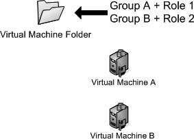
The following examples will demonstrate some various scenarios for permissions and how they interact in different situations. For each of these examples, the following will apply:
User A belongs to both Group A and Group B.
Role 1 has the Power On virtual machine privilege, which will allow a user or group to power on or resume on a virtual machine.
Role 2 has the Create Snapshot privilege.
In the first example shown in Figure 7.15, Group A has been granted Role 1 at the virtual machine folder level, and Group B has been granted Role 2 at the same level. Both have the Propagate to Child Objects option enabled. User A does not have any specific roles granted on any of the objects shown. Since User A does not have any specific permission granted, the user inherits the combined permissions granted to Group A and Group B and is able to power on and create snapshots for both virtual machines.
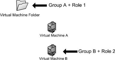
In the second example shown in Figure 7.16, Group A has been granted Role 1 at the virtual machine folder level. Group B has been granted Role 2 on Virtual Machine B. User 1 does not have any specific roles granted on any of the objects shown. In this case, the user will have the ability to power on Virtual Machine A through permission inheritance. However, Role 2 is assigned at a lower point in the vCenter object hierarchy, as shown in Figure 7.12. Thus, for Virtual Machine B, the privileges of Role 2 override the privileges granted in Role 1 at the virtual machine folder level. User 1 is only able to create snapshots on Virtual Machine B.
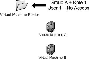
The last example, shown in Figure 7.17, demonstrates how user permissions will override group permissions. Group A has been granted Role 1 at the virtual machine folder level. User 1 has been granted the No Access system role at the same level. In this case, the permissions granted to the user override any group permissions and User 1 does not have any access to the folder or the virtual machines. In the vSphere client, the folder and virtual machines would not be visible. If User 1 had been granted the No Access role on Virtual Machine A, User 1 would have been able to power on Virtual Machine B, but would have no access to Virtual Machine A. In the vSphere client, Virtual Machine A would not be visible to User 1.
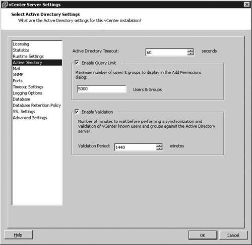
When using vCenter Server and assigning permissions to AD users and groups, it is important to understand how vCenter Server interacts with AD to validate users and groups. vCenter Server validates with AD when the VMware VirtualCenter Server Windows service is started. This occurs when the vCenter host is restarted or if you manually start the service. vCenter Server also periodically validates with AD. The default setting for this is every 24 hours, as shown in Figure 7.18. If a user were to be deleted in the domain, the corresponding permissions in vCenter Server granted to the individual’s user account would be removed at the next validation period. If a new account with the same name were to be added before the validation period had occurred, that new account would receive all permissions granted to the old account. Thus it is important to ensure that the Enable Validation setting is enabled and that the Validation Period is appropriate for your domain.
To change the validation period for your vCenter Server, use the following steps:
Start the vSphere client and connect to vCenter Server.
From the Administration menu, select vCenter Server Settings.
Select the Active Directory list item.
Uncheck Enable Validation to disable periodic validation updates. AD users and groups will still be validated whenever the vCenter Server service is started.
If you have validation enabled, you can change the Validation Period by setting a time in minutes.
Click OK to save your changes.
The validation period will also have an impact on the removal of permissions granted to users or groups. If you change a group or user name in Active Directory, when vCenter Server validates with AD, it will assume the group or user has been deleted and remove any permissions granted to the AD object. Also when you remove an AD user or group, the permissions will remain listed in vCenter Server until the next validation period.
When assigning permissions with a domain that contains thousands of users or groups, you may find that searches of AD take a long time. You can adjust other settings on the Active Directory vCenter Server Settings screen, shown in Figure 7.18. The settings are listed in Table 7.4.
Table 7.4. Active Directory Search List Settings
Setting | Description |
|---|---|
Active Directory Timeout | Searching a large domain can take a significant amount of time. This setting will set the maximum amount of time that vCenter Server will allow a search to run. |
Enable Query Limit | If this setting is disabled, vCenter Server returns all users and groups from Active Directory. |
Users & Groups | This setting specifies the maximum groups and users that vCenter Server displays if the Enable Query Limit option is enabled. |
Secure Sockets Layer (SSL) is a protocol originally designed by Netscape to enable servers and clients to securely pass information. SSL has been universally accepted on the Internet for authenticated and encrypted communication. The protocol makes use of a system of public and private keys to encrypt communication between hosts. The public key or certificate can be freely passed to any host, but the private key remains secured by the host that it was generated for and it is not shared with other hosts. To encrypt communication, the client and host use the SSL certificate in the following manner:
The client sends the server its SSL version number, cipher settings, some randomly generated data, and other information needed to communicate with SSL.
The server returns the same information along with its public certificate. If the server requires client authentication, it requests an SSL certificate for the client.
Using the data generated by the session, the client creates a premaster secret for the session, encrypts that with the server’s public certificate, and sends the encrypted result back to the server.
If the server has requested client authentication, the server will attempt to authenticate the client. If the client is successfully authenticated, the server uses its private key to decrypt the premaster key. The server then generates a master secret.
Both the server and client use the master key to create session keys. These are symmetric keys used to encrypt and decrypt communication between the two hosts.
The client and server both send a message to the other indicating that future messages will be sent encrypted with the session key. A separate message is sent indicating that the handshake is complete.
With the handshake complete, the SSL session has begun. Both the client and server use the session keys to encrypt and decrypt data sent. Any data that fails to be decrypted by the session keys is discarded because it may indicate packet tampering by a third host.
There are two kinds of SSL certificates that you may deal with in your vCenter Server infrastructure. Self-signed certificates have been generated by the server to which you are trying to connect. Use of self-signed certificates does not indicate that the session data will be less securely encrypted. The client host must implicitly trust the server host to be the server that it claims to be. Some applications will detect a self-signed certificate and warn the user of the situation. The following certificate error is generated when connecting with PowerCLI to a vCenter Server host with a self-signed certificate:
Connect-VIServer vcenter41.mishchenko.net
WARNING: There were one or more problems with the server certificate:
* The X509 chain could not be built up to the root certificate.
Name                               Port               User
----                               ----               ----
vcenter41.mishchenko.net           443                Administrator
The other kind of SSL certificate that you will encounter is one signed by a certificate authority (CA). A CA can be used by the client and server to confirm the validity of the SSL certificate being sent by the destination host. The CA used can be a well-known and publically trusted CA such as RSA or VeriSign, or it may be an internal CA set up as part of your company’s information technology (IT) infrastructure. In either case, the client or server trust the CA to verify the certificate and thus confirm the identity of the other host involved in the SSL session.
As noted earlier in this chapter, SSL encrypted traffic is used between the vSphere client and hosts, between vCenter Server and ESXi hosts, and, in certain functions, between ESXi hosts. Both ESXi and vCenter Server support SSL v3 and Transport Layer Security (TLS) v1, which will both be referred to as SSL. SSL v3 was released in 1996 and replaced SSL v2, which contained a number of security flaws. TLS was defined in 1999 as an upgrade to SSL v3. The differences between the protocols are not significant, but they are sufficient to make it necessary to prevent interoperation between the two.
Both products also install with a self-signed certificate. In the case of a vCenter Server host, the certificate is issued to VMware Default Certificate and signed by the VMware Installer, as shown in Figure 7.19. With VMware ESXi, the certificate for a default installation is issued to localhost.localdomain, as that is the default hostname after an installation. With a scripted installation, if you set the hostname, the certificate will be issued to the hostname that you have set in the installation script.
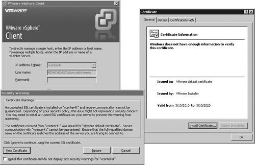
The Security Warning dialog box as shown in Figure 7.19 provides the following options when connecting to a host that has generated an SSL certificate warning:
Cancel. If you are not expecting a security warning and cannot guarantee that you are connecting to the correct host, select Cancel to close the vSphere connection request.
View Certificate. You can select the View Certificate to view details for the SSL certificate as shown in Figure 7.19. You can optionally choose Install Certificate on the Certificate dialog box to add this certificate to your Windows PC local certificate store.
Ignore. You can select the Ignore option to bypass the warning message and continue connecting to the host. You should choose this option if you are able to verify that you are connecting to the correct host. You will receive the Security Warning dialog box on your subsequent login to the host.
Install the Certificate and Do Not Display Any Security Warnings. If you select this option, an ignore entry will be stored in the registry of the Windows PC that you are using at the following location: HKEY_CURRENT_USERSoftwareVMwareVirtual Infrastructure ClientPreferencesUISSLIgnore. The certificate will also be stored in the certificate store for the Windows PC running the vSphere client.
When you receive a security warning, the details should be carefully reviewed. In some cases, the warning is generated due to detection of a self-signed certificate. In other cases, it may be that the hostname to which you are connecting does not match the hostname on the SSL certificate. Or it could be that the SSL certificate has expired and thus is no longer valid.
Regardless of the case of using self-signed certificates or a security warning being generated due to an SSL certificate problem, choosing to ignore the warning opens the possibility of a Man in the Middle Attack (MiTM). As noted earlier, even with self-signed certificates, network communication is encrypted and thus protected from casual network sniffing. But if it is not possible to verify the identity of the client or server involved in the SSL handshake, there is the possibility that a third host may launch a MiTM attack.
The following sections describe the process to replace the SSL certificates used by vCenter Server and ESXi with those generated by a trusted certificate authority. The processes use certificates created by a Windows 2003 Server certificate authority that has been set up as the enterprise CA for a Active Directory domain. The certificate requests are generated by the OpenSSL Toolkit, which you can download from this link: http://www.openssl.org/related/binaries.html. OpenSSL is run on a Windows server to generate the requests for both vCenter Server and the ESXi hosts, but you could follow the same process on a Linux server, and many distributions already include OpenSSL. You could likewise use certificates generated by a trusted, well-known CA. For additional information on the certificates used by vCenter Server and ESXi and the options to replace the certificates, you can refer to the ESXi Configuration Guide and http://www.vmware.com/pdf/vsp_4_vcserver_certificates.pdf.
To install OpenSSL on a Windows server, use the following process:
Open a Web browser and access the site http://www.openssl.org/related/binaries.html to find a download link for Windows binaries of OpenSSL.
Download a copy of the Microsoft Visual C++ 2008 Redistributable package. This can be found on http://www.microsoft.com.
After you have installed the C++ package, you can install OpenSSL. The default installation options are sufficient.
Optionally, you can edit the file openssl.cfg, which can be found in the
binfolder of your OpenSSL installation. The configuration file contains a number of settings that you can update to match your environment more closely.
The certificate files for vCenter Server are stored in C:UsersAll UsersVMwareVMware VirtualCenterSSL. The files stored in that folder include the private key (rui.key), the certificate file (rui.cer), and the Personal Information Exchange (PFX) file (rui.pfx). Use the following process to create a new SSL certificate for your vCenter Server:
Open a command prompt and access the OpenSSL
binfolder.Run the following OpenSSL command to generate the private key file:
openssl genrsa 1024 > rui.key
Loading 'screen' into random state - done
Generating RSA private key, 1024 bit long modulus
.........................+ + + + + +
.................+ + + + + +
e is 65537 (0x10001)
Run the OpenSSL command again using the private key file to generate a certificate request. The critical parameter is the common name, which should match the fully qualified domain name (FQDN) for your vCenter Server host.
openssl req -new -key rui.key > rui.csr -config openssl.cfg

Loading 'screen' into random state - done
You are about to be asked to enter information that will be incorporated
into your certificate request.
What you are about to enter is what is called a Distinguished Name or a DN.
There are quite a few fields but you can leave some blank
For some fields there will be a default value,
If you enter '.', the field will be left blank.
- - - - -
Country Name (2 letter code) [AU]:CA
State or Province Name (full name) [Some-State]:BC
Locality Name (eg, city) []:Surrey
Organization Name (eg, company) [Internet Widgits Pty Ltd]:Mishchenko
Organizational Unit Name (eg, section) []:IT
Common Name (eg, YOUR name) []:vcenter41.mishchenko.net
Email Address []:

Please enter the following 'extra' attributes
to be sent with your certificate request
A challenge password []:
An optional company name []:
Open a Web browser and access the URL for the Enterprise CA. This is typically http://<CA server>/certsrv.
Select the option Request a Certificate and then choose the link to submit an Advanced Certificate Request.
Choose the link Submit a Certificate Request by Using a Base-64-Encoded CMC or PKCS #10 File, or Submit a Renewal Request by Using a Base-64-Encoded PKCS #7 File.
Copy the contents of the
rui.cerfile into the Saved Request field, choose a template of Web Server, and then click Submit Request.On the Certificate Issued screen, select Base 64 Encoded and then download the certificate. Save the download to the OpenSSL
binfolder and name itrui.crt.Run the following OpenSSL command to create the PFX file:
openssl pkcs12 -export -in rui.crt -inkey rui.key -name rui -passout
   pass:testpassword -out rui.pfx
Loading 'screen' into random state - done
Copy the
rui.key,rui.crt, andrui.pfxfiles toC:UsersAll UsersVMware VMware VirtualCenterSSL.Switch back to the command prompt and change to the vCenter Server folder. This will likely be
C:Program FilesVMwareInfrastructureVirtualCenter Server. Run thevpxdcommand as shown in the following listing to reinitialize the vCenter Server database with the new certificate. You will be prompted for a new vCenter database password.C:Program FilesVMwareInfrastructureVirtualCenter Server>vpxd.exe -p FILE: FileDeletionRetry unmapped error code 32 [2010-06-09 21:51:32.930 04180 info 'Libs'] FILE: FileDeletionRetry unmapped error code 32 [2010-06-09 21:51:32.930 04180 info 'App'] Current working directory: C:Program FilesVMwareInfrastructureVirtualCenter Server [2010-06-09 21:51:32.930 04180 info 'App'] Log path: C:ProgramDataVMwareVMware VirtualCenterLogs [2010-06-09 21:51:32.945 04180 info 'App'] Initializing SSL [2010-06-09 21:51:32.945 04180 info 'Libs'] Using system libcrypto, version 9080BF [2010-06-09 21:51:34.273 04180 info 'App'] Vmacore::InitSSL: doVersionCheck = true, handshakeTimeoutUs = 120000000 Enter new DB password: again: [2010-06-09 21:52:14.929 04180 info 'App'] Reset DB password succeeded.Restart the VMware VirtualCenter Server service. This also restarts the VMware VirtualCenter Management Webservices service.
Once you have completed this process, you can start the vSphere client and connect to your vCenter Server. You should no longer experience a certificate error when you start the vSphere client. After you have logged in to vCenter Server, you will observe that all hosts are disconnected. vCenter Server uses the SSL certificate to encrypt and decrypt the password for the vpxuser account, which is used to connect to your ESXi hosts. With a change in SSL certificate, vCenter Server is no longer able to connect to the hosts and they appear disconnected. After you replace the SSL certificate on your hosts, you should reconnect the hosts. Ideally, the virtual machines on the hosts should be powered down for that operation. When you reconnect the hosts, you will be prompted for an administrator login to the host, and after you have authenticated with the host the vpxuser password is reset and saved to the vCenter Server database again after being encrypted with the new SSL certificate. Given the scope of this change, it is worthwhile to ensure that you have a backup of the vCenter Server host and the database before you attempt this procedure.
Replacing the SSL Certificate for Update Manager
If you have installed Update Manager, you may have still noticed a certificate warning when connecting to your vCenter Server. This is due to Update Manager using its own self-signed certificate. There is not a supported method that is published at this time to replace your Update Manager SSL Certificate, but you can use the following process to accomplish that. This process assumes that the Update Manager database is hosted on a dedicated database server and that you are not using Microsoft SQL Express. Update Manager stores the SSL files for its services in C:Program Files (x86)VMwareInfrastructureUpdate ManagerSSL. The installation process for Update Manager is documented in Chapter 10, “Patching and Updating ESXI.”
If you’re running Update Manager on the same host as vCenter Server, copy the SSL file that you generated using the process documented earlier to the folder
C: Program Files (x86)VMwareInfrastructureUpdate ManagerSSL. If you are running Update Manager on another host, use the same process to create a new set of files for the SSL certificate.Uninstall Update Manager. To prevent a reboot of the host, stop the two Update Manager services before starting the uninstall process.
Reinstall Update Manager with the exact same settings that you used initially to install the product.
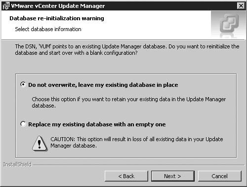
After you supply your Update Manager database credentials, you will see the Database Re-initialization Warning screen, as shown in Figure 7.20. Choose the default option of Do Not Overwrite, Leave My Existing Database in Place.
Start the vSphere client and connect to the vCenter Server with which Update Manager is registered. Verify that your previous configuration settings are still in place.
The process for replacing a certificate on an ESXi host is very similar to the process for vCenter Server. For ESXi, only the private key (rui.key) and the certificate file (rui.cer) file are copied to the ESXi host with vifs from the vCLI. ESXi does not require the PFX file (rui.pfx). These files are stored in /etc/vmware/ssl as well as in the configuration backup file that ESXi uses to maintain configuration settings between reboots. Use the following process to create a new SSL certificate for your ESXi host. You should generate a unique rui.key and rui.crs file for each of your ESXi hosts.
Open a command prompt and access the OpenSSL
binfolder.Run the following OpenSSL command to generate the private key file:
openssl genrsa 1024 > rui.key
Loading 'screen' into random state - done
Generating RSA private key, 1024 bit long modulus
.........................+ + + + + +
..................+ + + + + +
e is 65537 (0x10001)
Run the OpenSSL command again using the private key file to generate a certificate request. The critical parameter is the common name, which should match the fully qualified domain name for your vCenter Server host.
openssl req -new -key rui.key > rui.csr -config openssl.cfg

Loading 'screen' into random state - done
You are about to be asked to enter information that will be incorporated
into your certificate request.
What you are about to enter is what is called a Distinguished Name or a DN.
There are quite a few fields but you can leave some blank
For some fields there will be a default value,
If you enter '.', the field will be left blank.
- - - - -
Country Name (2 letter code) [AU]:CA
State or Province Name (full name) [Some-State]:BC
Locality Name (eg, city) []:Surrey
Organization Name (eg, company) [Internet Widgits Pty Ltd]:Mishchenko
Organizational Unit Name (eg, section) []:IT
Common Name (eg, YOUR name) []:esx08.mishchenko.net
Email Address []:

Please enter the following 'extra' attributes
to be sent with your certificate request
A challenge password []:
An optional company name []:
Note
ESXi does not support pass-phrase SSL certificates. Such a certificate will prompt a user for a password each time the server process using the certificate starts. With ESXi this will cause service failures, and the host will not operate properly. If you are using OpenSSL, you should enter nothing for the A Challenge Password field.
Open a Web browser and access the URL for the Enterprise CA. This is typically http://<CA server>/certsrv.
Select the option Request a Certificate and then choose the link to submit an Advanced Certificate Request.
Choose the link Submit a Certificate Request by Using a Base-64-Encoded CMC or PKCS #10 File, or Submit a Renewal Request by Using a Base-64-Encoded PKCS #7 File.
Copy the contents of the
rui.cerfile into the Saved Request field, choose a template of Web Server, and then click Submit Request.On the Certificate Issued screen, select Base 64 Encoded and then download the certificate. Save the download and name it
rui.cer.Run the following command to convert the certificate to the x509 format:
openssl x509 -in rui.cer -out rui.crtCopy the
rui.keyandrui.crtto the host withvifsfrom the vCLI:vifs - -server esx08.mishchenko.net - -put rui.key /host/ssl_key Uploaded file rui.key to ssl_key successfully. vifs - -server esx08.mishchenko.net - -put rui.crt /host/ssl_cert Uploaded file rui.crt to ssl_cert successfully.
Access the DCUI and restart the management services for the host. The new certificate will be loaded when the services restart.
After you have replaced the SSL certificate on your host, you will need to reconnect your host to vCenter Server. Right-click on the ESXi host and select Connect. You will receive an error that the host cannot be reconnected due to a login failure. Click OK and the Add Host wizard will begin to allow you to reconnect your host.
With vCenter Server, you can enable verification of host SSL certificates. This option is enabled by default and it is recommended to leave this setting enabled. The verification process affects operations such as adding a host, connecting to a virtual machine, and making virtual machine devices remotely available. This option is required for Fault Tolerance to operate.
To verify the SHA1 thumbprint of certificates on hosts, follow this procedure:
Start the vSphere client and connect to vCenter Server.
Select Administration > vCenter Server Settings.
Select SSL Settings in the left pane and check the vCenter Requires Verified Host SSL Certificates option.
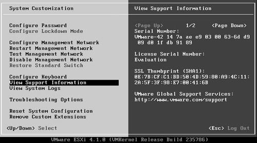
For hosts that require verification, the SHA1 thumbprint will be displayed as shown in Figure 7.21. Compare that to the value shown in the DCUI as displayed in Figure 7.22. If you don’t have DCUI access, you can download the certificate file from the ESXi host with
vifsand then run the following OpenSSL command to generate the SHA1 thumbprint:openssl x509 - -in rui.crt - -fingerprint - -sha1 -noout
If the values match, check the Verified option.
Click OK to close the window.

Internet Protocol Security (IPSec) is a protocol suite designed to secure Internet Protocol (IP) communications by authenticating and encrypting each IP packet of a data stream between two hosts. IPSec includes protocols to establish mutual authentication between hosts at the start of a session and negotiation of cryptographic keys to be used to transmit data during a session. IPSec is integrated into the Internet layer (Layer 3 of the Open System Interconnection model) and thus can function transparently to the applications that are running on the hosts. IPSec provides a defense in depth against the following security concerns:
Data corruption
Data theft
User credential theft
Network-based attacks from untrusted computers, such as denial-of-service attacks and replay attacks
To set up a secure path for communication using IPSec, two hosts perform the following tasks:
The hosts agree upon a set of security protocols to use.
The hosts decide on the specific security algorithm to use to encode data.
The hosts exchange keys that are used to decrypt data that has been received from the other host.
After the IPsec session has been established, the hosts use the protocols, methods, and keys previously agreed upon to transfer data in a secure manner.
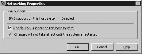
VMware ESXi 4.1 introduces support for IPSec using Internet Protocol version 6 (IPv6). IPSec is not supported for Internet Protocol version 4 (IPv4). The significant difference between IPv4 and IPv6 is the address length. IPv4 is limited to a 32-bit address whereas IPv6 uses a 128-bit address, which alleviates the current Internet problem of address exhaustion. The IPv6 implementation in ESXi supports addresses assigned by DHCP, configured by stateless configuration, sent by router advertisements, and entered statically. Before you can configure IPSec on your ESXi host, you must first enable IPv6, which is disabled by default. You can use the following process to enable IPv6 on your host. It is also possible to enable and configure IPv6 for the management network using the DCUI as shown in Chapter 3.
Start the vSphere client and connect to your ESXi host. You can connect directly to the host or to the vCenter Server managing the host.
Select the Configuration tab.
Select Networking under Hardware.
In the Virtual Switch view, click the Properties link.
Enable the option Enable IPv6 Support on This Host System and click OK as shown in Figure 7.23.
After the host has rebooted, return to the Configuration tab for the host and select the Networking link again.
Click the Properties link for the virtual switch that contains the management network.
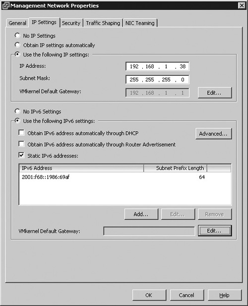
Select the Management Network port and click Edit.
Select the IP Settings tab and you will see the IPv6 configuration settings as shown in Figure 7.24. You can enable the host to obtain an IPv6 address from a DHCP server, through Router Advertisement, or set a static IPv6 address.
Optionally, you can click Edit to set an IPv6 VMkernel Default Gateway. You can click Advanced to view addresses assigned via DHCP or Route Advertisement.
Click OK and then Close to save your changes.
Once you have enabled your ESXi host for IPv6, you are ready to configure IPSec. Configuration of IPSec is performed with the vCLI command vicfg-ipsec. In the following examples, a host is configured to secure vSphere client traffic with IPSec and also to block certain types of traffic and other hosts from communicating with your ESXi host.
When you enable IPsec on your host, you configure both authentication and encryption of incoming and outgoing network packets. There are two elements to enabling this setup. First, you create a security association that determines how the system will encrypt traffic. A security association includes the source and destination IPv6 addresses, encryption parameters, and a name for the security association. The second element is a security policy. The policy determines when the host should encrypt, discard, or allow traffic to pass unencrypted. A policy includes the source and destination IPv6 addresses, the protocol, and the direction of traffic that should be encrypted, and the mode and security association to use.
To begin the process of configuring IPSec, you run the following command to create a security association between the host, which has an IPv6 address of 2001:0F68::1986:69AF, and the management server which has an IPv6 address of 2001:0F68::1986:69AD:
vicfg-ipsec --server esx08.mishchenko.net --add-sa --sa-src 2001:0F68::1986:69AD
   --sa-dst 2001:0F68::1986:69AF --sa-mode transport --spi 0x1000
   --ealgo 3des-cbc
   --ekey 0x6970763672656164796c6f676f336465736362636f757432
   --ialgo hmac-sha1 --ikey 0x6970763672656164796c6f67736861316f757432
   sa1
The parameter --add-sa indicates that the command is going to create a new security association on the host. The option --spi is used to create a security parameter index. The security parameter index is used to identify the security association to the host. It must be a hexadecimal value and a prefix of 0x. Each security association that you create on the host will have a unique combination of protocol and security parameter index. The --ealgo option indicates the encryption algorithm that will be used; you have an option between 3des-cdc, aes128-cbc, and none. The --ialgo parameter indicates the authentication algorithm, and the options are hmac-sha1 and hmac-sha2-256. The –ekey option is the encryption key used by this security association. The value is specified as a hex value and preceded with 0x. Lastly, the parameter –ikey is the authentication key. This is also a hex value. For authentication, ESXi supports the use of pre-shared keys. Both hosts involved in the IPSec session must be configured with the same authentication key. When establishing a session, the hosts compute and exchange a keyed hash of data that includes the pre-shared key. If the receiving host is able to create the same hash using its pre-shared key, it is able to determine that both hosts share the same authentication key. If your vicfg-ipsec command has a syntax error, the following error is returned. If the security association is created, no output will be generated.
Could not add Security Policy: A specified parameter was not correct.
To view the security association that you created, you can run the following command: vicfg-ipsec --server esx08.mishchenko.net --list-sa
SA Name  Src Addr        Dst Addr         State   SPI
   Mode   Encrypt Algo Auth Algo    Soft Lifetime Hard Lifetime
sa1     2001:f68::1986:69ad  2001:f68::1986:69af  mature  0x1000
   transport 3des-cbc   hmac-sha1      infinite    infinite
To create a security policy, you can use the vicfg-ipsec command with the option --add-sp. This policy enables IPSec encryption on vSphere client traffic coming from the management server to the ESXi host. The policy also includes the source and destination addresses, but in the case of creating the policy, you must include the prefix length as shown in the following example. The policy also includes the source and destination ports. The source port is specified as 0, as the originating port is dynamically allocated by the management computer when the vSphere client initiates a network connection. The -ulproto parameter specifies the upper-layer protocol; in this case, it is tcp. The traffic direction is specified by the --dir option, and in this case, the --action parameter is ipsec. Other options for --action include discard, which will drop the traffic matching the policy, and none, which allows matching traffic to pass unencrypted. The policy is set to use transport mode and it is linked to the security association called sa1. Lastly, the security policy is named sp1.
vicfg-ipsec --server esx08.mishchenko.net --add-sp
     --sp-src 2001:0F68::1986:69AD/128 --sp-dst 2001:0F68::1986:69AF/128
     --src-port 0 --dst-port 443 --ulproto tcp --dir in --action ipsec
     --sp-mode transport --sa-name sa1 sp1
Once you have created a security policy, you can run the following command to review the security policies that exist on the host:
vicfg-ipsec - -server esx08.mishchenko.net - -list-sp

SP Name  Src Addr          Src Port  Dst Addr         Dst Port
   Protocol  Flow     Action     Mode     SA Name
sp1     2001:f68::1986:69ad/128 0       2001:f68::1986:69af/128 443
   tcp     in      ipsec     transport  sa1
At this point, your management server cannot connect to your ESXi host, as ESXi requires communication via IPSec with the vSphere client. When you attempt to connect with the vSphere client, an error message similar to Figure 7.25 is displayed. Setup of IPSec varies between operating systems and network devices. The following example shows the setup for IPSec on Windows 2008 Server. This setup assumes that IPv6 has already been correctly configured on the host.
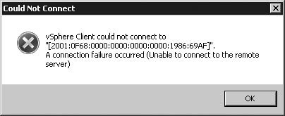
Open a Microsoft Management Console (MMC) windows by selecting Start > Run and entering
mmc.Select File > Add/Remove Snap-in and then add the span-in IP Security Policy Management. The snap-in should be opened for the Local Computer.
Right-click on IP Security Policies on Local Computer and select Manage IP Filter Lists and Filter Actions.
On the Manage IP Filter Lists tab, click Add to create an IP filter.
Enter a Name and Description for the new filter. Then click Add to create the IP filter.
The IP Filter wizard starts. Optionally, enter a Description and click Next.
On the IP Traffic Source screen, change the Source Address to My IP Address and click Next.
On the IP Traffic Destination screen, select A Specific IP Address or Subnet and enter the IPv6 address for your ESXi host. Click Next to continue the wizard.
On the IP Protocol Type screen, you can change the Protocol Type to TCP and then click Next.
Select the option To This Port and enter a value of 443. The source port should be left as From Any Port. Click Next to complete the wizard and then Finish to close it.
You should now see the new IP Filter List as shown in Figure 7.26. Click OK to close the window.
Select the Manage Filter Actions and click Add.
Enter a Name and Description for your filter action and click Next.
The default choice on the Filter Action General Options screen is Negotiate Security. Click Next to continue. Similar to the security policy you created on ESXi, the other action options are Block, to drop traffic that matches the filter, and Permit, to allow matching traffic to pass unencrypted.
The Do Not Allow Unsecured Communication is fine on the Communicating with Computers That Do Not Support IPSec screen. The other option to allow unsecured communication if a secure connection cannot be established will not work with the configuration that has been established on ESXi.
Choose the option Integrity and Encryption on the IP Traffic Security screen and click Next.
Click Finish to save your new IP Security Filter.
The Manage Filter Actions tab should now display the filter action that you created. Click Close to dismiss the Manage IP Filter Lists and Filter Actions window.
Right-click on IP Security Policies on Local Computer and select Create IP Security Policy.
The IP Security Policy wizard begins. Click Next to continue.
Enter a Name and Description for the policy and click Next.
Click Next on the Requests for Secure Communication screen as the default setting is sufficient.
Click Finish to close the wizard. The Edit Properties check box is enabled, which brings up the properties for the policy for further editing.
Click Add on the Rules tab to start the Security Rule wizard.
Click Next on the Security Rule welcome screen to proceed.
Click Next on the Tunnel Endpoint, as the default option of This Rule Does Not Specify a Tunnel is correct.
The default choice of All Network Connections on the Network Type screen is fine. Click Next to continue.
On the IP Filter List screen, select the IP filter that you created earlier and click Next.
On the Filter Action screen, select the filter action that you created and click Next.
On the Authentication Method screen, select the option Use This String to Protect the Key Exchange (Preshared Key). When you created the security policy on ESXi, the value specified for the pre-shared key was in hexadecimal format. The value that is entered on the Authentication Method screen is entered as ASCII text, as shown in Figure 7.27. Click Next to Continue.
Click Finish to save the new security rule.
The security policy dialog box should now display the new security rule, as shown in Figure 7.28. Click OK to close the window.
To enable the security policy, right-click on the policy and select Assign.
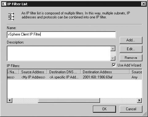
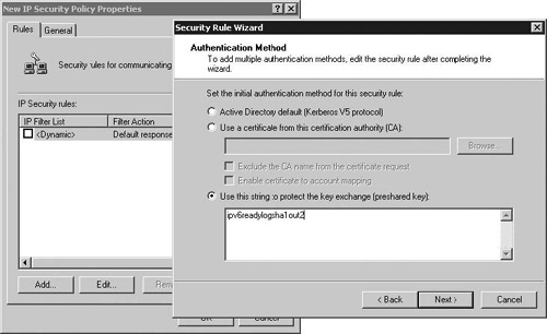
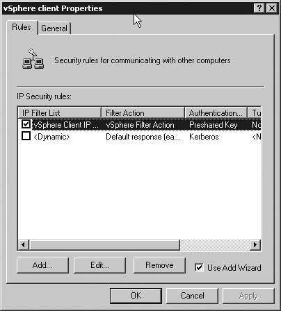
After you have completed this setup, you can now attempt to connect with the vSphere client. If a connection is established, the traffic passed between your management computer and your ESXi host will be secured with IPSec. Should you experience any issues making the connection, you can use the Microsoft IPSec Diagnostic Tool, which is available from http://support.microsoft.com/kb/943862. This tool can display IPSec policy information for your computer, and it parses the IPSec logs to determine the potential cause of any IPSec failures.
You can also configure your host to block traffic from specific hosts or subnets. In the following example, the protocol setting has been changed to any and both the source and destination ports are set to 0. These settings impact all traffic coming from the host specified with the source parameter. The security policy has also been set to discard any traffic that meets the traffic filter.
 vicfg-ipsec - -server esx08.mishchenko.net - -add-sp
     - -sp-src 2001:0F68::1986:69AE/128 - -sp-dst 2001:0F68::1986:69AF/128
     - -src-port 0 - -dst-port 0 - -ulproto any - -dir in - -action discard
     - -sp-mode transport - -sa-name sa1 sp2
A single host deployment is likely to use local storage, and for the most part you need to be significantly concerned about the security of your storage. But as you add ESXi hosts, there are compelling reasons to move to some form of shared storage. ESXi supports Fibre Channel (FC) storage area network (SAN), iSCSI, and NFS storage. Practically, as you consolidate your storage, you can reduce your hardware costs, reduce your storage management overhead, and more effectively use your disk resources. Numerous vSphere features such as vMotion, High Availability, and Fault Tolerance require some form of shared disk resource.
This section of the chapter deals with some of the common security concerns with using shared storage. As has been mentioned earlier in this chapter, the key to securing your storage is isolation. Depending on your deployment, that will involve a mix of vSwitch design, employment of VLANs, and physical network separation. FC SAN, iSCSI, and NFS are all clear text protocols and thus vulnerable to MiTM attacks. With a packet sniffer, it is also possible to capture traffic, which allows for the discovery of classified data.
Note
One of the keys to security is physical security. If an intruder can gain physical access to a host, it becomes a very simple task to be able to remove the virtual machines running on that host. There are drivers that will allow a Linux or Windows machine to read a Virtual Machine File System (VMFS) datastore, in which case the virtual machines could be copied to another storage media or across the network to another device. It is even possible to create a Live CD that can be used to launch an independent copy of ESXi, which would then be able to run the virtual machines’ hosts on the comprised host. If you cannot physically secure your ESXi hosts, consider using encryption within the guest operating system to add another layer of protection to your data.
With a traditional FC SAN deployment, each ESXi host contains an FC Host Bus Adapter (FC-HBA) that connects to an isolated storage network. Each FC-HBA has what is essentially a storage Media Access Control (MAC) address called a worldwide port name (WWPN). For security, the SAN presents a storage logical unit number (LUN) to the WWPN. The ESXi host with that FC-HBA is then able to access that storage LUN and use it as needed. The SAN can also be configured to provide access to a single LUN to a number of WWPNs. In this way, the LUN is configured to be shared among several ESXi hosts to allow for clustering. If a host fails, the FC-HBA can be moved to another host and the new host will have the same LUN access as the old host. While this is a benefit to recovery, it also poses a security concern, as the new host has no requirement to authenticate or validate its identity with the SAN. When configuring your SAN, you must carefully ensure that the LUNs are zoned to the appropriate WWPNs.
As Fibre Channel storage evolves as a technology, new security concerns come to light. With the emergence of Fibre Channel over Ethernet (FCOE), it is possible to send FC data over your Ethernet network. While this technology provides the opportunity to converge your network design, you must consider the risk of comingling your storage data with other network data types.
Another new Fibre Channel technology to be aware of is N_Port ID Virtualization (NPIV). With NPIV, a virtual machine can be granted an identity in the FC storage fabric. Instead of just granting access to a LUN to a host and all the virtual machines running on that host, the SAN administrator can grant access to a specific virtual machine. This provides an additional layer of LUN masking and allows the SAN administrator to identity traffic for that specific virtual machine.
VMware ESXi supports NFS version 3 over TCP. NFS storage is easy to set up, but it represents the least secure level of storage that you can use with ESXi. Authentication is often based upon an IP address, which can be spoofed. NFS is a clear text protocol, and ESXi authenticates with the NFS storage with the root login. Additionally, accessing NFS from ESXi requires that the no_root_squash option be enabled. With root squashing, the root account is mapped to another unprivileged account such as nobody on the NFS server to prevent root accounts on client machines from gaining privileged access to the NFS mounts. ESXi, however, requires read and write access to the mounts, so it is necessary to disable root squashing.
If you employ NFS storage, the primary concern is traffic isolation. If your environment requires physical separation, your NFS storage should be on a physically isolated network, and the vSwitch that connects to that network should have only a VMkernel port configured on it. No virtual machine port groups should be in that vSwitch, to prevent a virtual machine from attempting to attack or capture network traffic from the NFS server. You can also configure the NFS server to restrict access to the specific IP addresses of your ESXi host or use a firewall to restrict traffic to a specific host. If your NFS server supports IPSec, you might also consider configured IPSec for the traffic between your ESXi host and NFS server. If you are employing blade servers with a minimal number of NICs or 10GB networking, you should ensure that NFS traffic is isolated with a VLAN.
Provisioning iSCSI storage is similar to Fibre Channel storage in that storage LUNs are presented to hosts that then choose how to partition and format the LUN. Access to your iSCSI storage can be via iSCSI Host Bus Adapters, which offload the overhead associated with iSCSI, or with standard NICs configured within your ESXi host’s vSwitches.
Given that iSCSI traffic is over an IP-based network, it is vulnerable to the attacks discussed throughout this chapter. As with the other storage options, isolation is the first step to securing iSCSI. The iSCSI protocol supports the use of Challenge-Handshake Authentication Protocol (CHAP), but post authentication traffic is sent in clear text. As is the case with NFS traffic, consider the use of IPSec to secure traffic between your ESXi hosts and iSCSI target. You might also consider the use of firewalls to protect the hosts involved. When you use iSCSI, ESXi does not open any ports to listen for network connections. This reduces the attack surface of your ESXi host, but you should still isolate the VMkernel port that is used for iSCSI access from general network traffic.
When designing your networking for iSCSI, it is ideal to be able to separate your iSCSI traffic either physically or with the use of a VLAN. If you are using iSCSI-HBAs, these devices will connect directly to your isolated network ports. If you’re using the software iSCSI initiator within ESXi, you will configure a new vSwitch for storage traffic, and then configure this vSwitch to connect to the isolated storage network.
When configuring iSCSI storage for your ESXi hosts, you should enable CHAP authentication. When the ESXi initiator contacts the iSCSI target, the target responds with a predefined ID value and a random key. The initiator then creates a one-way hash value that it sends to the target. The hash contains the ID value, random key, and the CHAP secret that has been configured on both the ESXi host and iSCSI server. When the target receives the hash value, it computes its own hash value for the same elements. If both hashes match, the iSCSI target has verified the identity of the initiator.
ESXi supports both unidirectional and bidirectional CHAP. With unidirectional CHAP, only the iSCSI target authenticates the ESXi host. With bidirectional CHAP, the ESXi host also authenticates the iSCSI target providing an additional layer of security. It is possible to disable CHAP authentication, and the ESXi host will still authenticate in a very simple manner in that the iSCSI target will map a LUN to the unique iSCSI name for the host. This is not a recommended method to set up your iSCSI access.
To enable CHAP authentication, you can follow this process:
Start the vSphere client and connect either to your vCenter Server or directly to your ESXi host.
Select the Configuration tab for the host and then click the Storage Adapters link in the Hardware panel.
In the list of storage adapters, choose the iSCSI initiator and click Properties.
If the iSCSI initiator has been enabled, click CHAP.
Select an authentication option for CHAP (Target Authenticates Host), as shown in Figure 7.29. You have the following four options: Do Not Use CHAP, Do Not Use CHAP unless Required by Target, Use CHAP unless Prohibited by Target, and Use CHAP.
To use the iSCSI initiator name to identify the host to the iSCSI target, check the Use Initiator Name option. Otherwise, enter a name that the iSCSI target will be configured to recognize. Enter the Secret, which matches the password setup on the iSCSI target.
Optionally, you can configure the same settings for Mutual CHAP. The secret you configure for Mutual CHAP must be different from the one used for CHAP (Target Authenticates Host).
Click OK to close the CHAP Credentials window.
Click Close to close the Properties window for the iSCSI initiator. You will be prompted with a dialog box requesting a rescan of the host bus adapter due to the configuration change.
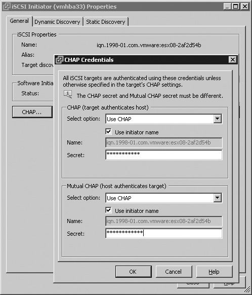
The preceding process configured CHAP authentication at the adapter level, and these settings and credentials would apply to all iSCSI targets that the host would attempt to access. You can also configure CHAP authentication on a per-target basis, which allows for greater security. When you add or modify a dynamic or static iSCSI target, you can click the CHAP button to access CHAP settings that will apply only to that specific target.
A common theme throughout this chapter has been the need to isolate traffic types. You don’t want DMZ virtual machines having access to your storage network, nor should the management interface for ESXi be exposed directly to your local area network (LAN). The same network principles that you’ll use when designing your physical network security will apply when configuring vSphere networking. If your server design includes many network ports, it may be relatively easy to segment network traffic with the use of many vSwitches each connected to physically isolated networks. But as network speeds increase and hardware size decreases, it becomes more likely that you’ll be running an ESXi host with only a few network ports. When configuring the security of your vSphere environment, networking represents the most significant avenue through which an attacker may impact not only your virtual machines but the network infrastructure surrounding them.
In the cases where you have a limited number of network ports to configure, you have to rely on VLANs to segment your network traffic. There is a fair bit of debate of the security capabilities of VLANs, as they have been subject to attacks and circumventing in the past. However, the technology has matured and the vSwitch provides safeguards against certain threats to VLAN security, including the following:
MAC flooding. This attack floods a switch with packets that contain MAC addresses from different sources. Switches track the source address for each packet, and if the MAC table fills, it is possible for the switch to enter a fully open state in which every packet is broadcast to all ports. In such a state, packet leakage across VLANs may occur. Although VMware vSwitches do track MAC addresses, the data does not come from observable traffic and thus a vSwitch is not vulnerable to this type of attack.
802.1q and Cisco Inter-Switch Link (ISL) tagging attacks. These force a switch to redirect packets from one VLAN to another by tricking the switch into acting as a trunk. vSwitches do not perform the dynamic trunking required for this type of attack.
Double-encapsulation attacks. These create a packet in which a VLAN tagged packet is encapsulated within another VLAN tagged packet. Some switches are configured to strip away the outer packet and pass on the inner VLAN tagged packet for backward compatibility. vSwitches drop any double-encapsulated packets that are sent.
Multicast brute-force attacks. These involve sending a large number of multicast packets to a known VLAN almost simultaneously to overload the switch so that it inadvertently allows some of the packets to be broadcast to other VLANs. vSwitches do not allow packets to leave their correct broadcast domain (VLAN) and are not vulnerable to this attack.
The preceding list is not exhaustive and both technologies and security threats develop over time. However, use of VLANs in your vSwitches is a viable option for providing network isolation. Perhaps a more significant risk in using VLANs is the possibility of misconfiguration.
vSphere includes a number of improvements with permissions. An example includes the additional choices for network configuration for a virtual machine, as shown in Figure 7.30. In prior versions of ESXi and ESX, it was only possible to assign a Remove permission. With vSphere, you can also control the assignment of a virtual NIC to a vSwitch. You can also utilize Distributed Virtual Switches and Host Profiles to ensure consistent configurations across your ESXi host. There are also additional permissions you can control for Distributed Virtual Switches. Properly configured, these elements can help reduce the risk of a virtual machine or vSwitch being misconfigured either intentionally or accidentally, which could expose a virtual machine to an unauthorized VLAN.
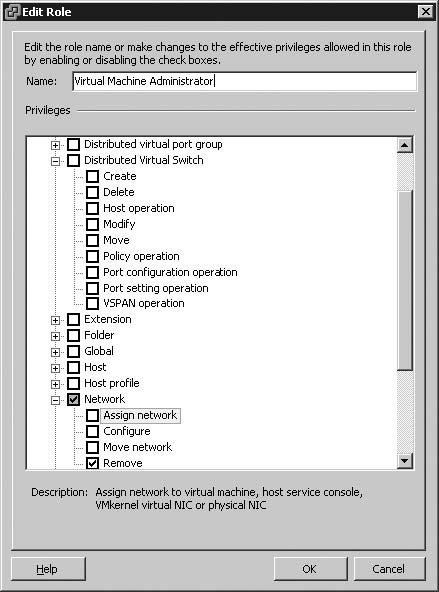
You should also be aware that VMware vSwitches do not support the concept of a native VLAN. Native VLANs are used by switches for switch control and management. Native VLANs are not tagged with a VLAN ID in some switch implementations, and trunk ports treat all untagged packets as belonging to the native VLAN. If you have created a number of virtual machine port groups in your switch, assigned them VLANS, but left one port group as unset, traffic from that port group could end up on the native VLAN of your physical switches. If your physical switches use VLAN ID 1 for the native VLAN, you should configure your vSwitches with VLAN IDs in the range of 2 to 4094. If another VLAN ID is used for the native VLAN, you should avoid using that VLAN ID on your vSwitches.
Use of VLAN ID 4095 enables Virtual Machine Guest Tagging (VGT) mode. In this mode, the vSwitch port group passes packets to the virtual machines without modifying any VLAN tags. It is the responsibility of the guest operating system to assign a VLAN ID to packets that it sends. If enabled inappropriately, this could allow a virtual machine to interact with a VLAN for which it is not authorized.
The properties for vSwitches and port groups include a number of security policies designed to safeguard your network. From the perspective of the guest operating system, the virtual NIC functions just as a physical NIC would, so a malicious program executing within the virtual machine is capable of forging MAC addresses or flooding the network to create a DoS attack. There are three security options that you can set to prevent malicious activity, and you can set limits on network traffic to prevent excessive network load.
To make changes to the security policy or traffic shaping policy of a vSwitch, you can follow these steps:
In the vSphere client, select the Configuration tab for a host and then select the Networking link in the Hardware pane.
For the vSwitch you wish to configure, select Properties.
Select the vSwitch port and click Edit.
Select the Security tab to display the security policy options shown in Figure 7.31.
Select the Traffic Shaping tab, shown in Figure 7.32. From this tab, you can configure the traffic settings for the vSwitch.
Make any desired changes and click OK, and then Close to complete the changes.
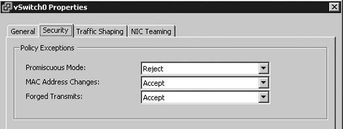
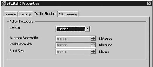
The first setting on the Security tab is Promiscuous Mode. The option is by default set to Reject. This eliminates the possibility that the virtual machine could be used to capture all traffic on the vSwitch, as the vSwitch will filter network traffic to ensure that the virtual machine receives only packets destined for that specific virtual machine. In some cases, if you are running a network sniffer or intrusion detection software, you may need to allow Promiscuous Mode on a vSwitch, but for most vSwitches, this setting can be left with the default setting.
The second option to configure is MAC Address Changes. This option is set to Accept. When a virtual NIC is added to a virtual machine, it is automatically assigned a MAC address. The guest operating system can change the MAC address and will begin to receive traffic destined for the new MAC address. This can be required in some situations such as using Microsoft Network Load Balancing in unicast mode. Additionally, the iSCSI initiator relies on being able to get MAC address changes from some types of storage. If the setting is change to Reject, ESXi will not honor a request by the virtual machine to change the MAC address from the initial value.
The last setting on the Security tab is Forged Transmits. When the option is set to Accept, ESXi does not compare source and effective MAC addresses. To protect against MAC impersonation, you can set this option to Reject. With that setting, ESXi compares the source MAC address as generated by the guest operating system with the effective MAC address for the adapters and drops the packet if there is not a match. This setting can impact applications that require a specific MAC address for licensing.
On the Traffic Shaping tab, you can set the traffic shaping policy for the vSwitch. This can be useful to ensure that a virtual machine is not used to saturate a vSwitch, which could create a DoS for other virtual machines or ESXi system services on that vSwitch. The traffic shaping policy is defined by the following three attributes: Average Bandwidth, Peak Bandwidth, and Burst Size. Average Bandwidth sets the bits per second to allow through the port averaged over time. Peak Bandwidth is the maximum number of bits per second allowed through the port when it is receiving or sending a burst of traffic. This setting, along with Burst Size, allows a vSwitch to transmit beyond the Average Bandwidth restriction. The Burst Size setting specifies the maximum number of bytes to allow in a burst of network traffic.
If you select the properties for a virtual machine port group or VMkernel port, the Security and Traffic Shaping tabs can also be found on these objects. You can check an option as shown in Figure 7.33 to override the setting enabled on the vSwitch. If you make no changes, the settings for the virtual machine port group or VMkernel port inherit the settings from the vSwitch.
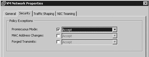
When used within a vSphere environment, the term clustering can refer to a number of different forms of clustering. At the host level, the most basic form of a cluster exists when two or more hosts share the same storage. ESXi supports shared storage using either VMFS-formatted LUNs or NFS mounts.
Many of the features in vSphere build upon the simple host clustering of storage. vMotion enables a running virtual machine to be migrated from one host to another while the virtual machine continues to execute uninterrupted. vMotion uses VMware’s cluster file system to control access to the virtual machine’s virtual disks. When a virtual machine is migrated from one host to another, the virtual machine’s active memory and execution state are transmitted over the vMotion network to the new host. This transfer of data occurs in clear text. A number of technologies within vSphere are dependent on vMotion. Dynamic Resource Scheduling (DRS) is a feature that allows virtual machines to be migrated by vMotion to a less constrained host should the host running the virtual machine be low on CPU or memory resources. Distributed Power Management allows hosts within a cluster to migrate virtual machines and power down during off hours to conserve power resources. Storage vMotion allows not only the virtual machine to migrate to another host without interruption but also allows for the movement of the virtual machine’s storage to another host datastore.
VMware High Availability (HA) is designed to detect the failure of a host or virtual machine. In the case of a virtual machine failure, it is restarted on the same host. With an unforeseen host failure, the virtual machines that were running on the failed host are restarted on other hosts within the HA cluster. VMware Fault Tolerance (FT) leverages HA clusters to create a shadow copy of a virtual machine on another host. The two virtual machines are kept in sync with VMware vLockStep technology. The secondary virtual machine executes the same sequence of virtual instructions as the primary guest. In the case of a failure or interruption in the primary virtual machine, the secondary guest completes outstanding input/output (I/O) requests, becomes the new primary virtual machine, and severs communication with the failed virtual machine.
Virtual machines can also be clustered in a number of different configurations. You may deploy some form of network load balanced (NLB) cluster or a shared disk cluster. A shared disk cluster could involve two virtual machines on the same host, virtual machines on two separate hosts, or a virtual machine paired in a cluster with a physical host.
A significant part of any cluster will be heartbeat traffic between the hosts or virtual machines involved in the cluster. These heartbeats will be used to determine the availability of services and control what actions are taken in the cluster. From a security perspective, it is critical to protect that heartbeat traffic, as it could provide an attack avenue for a DoS. With ESXi, VMware HA communication travels over VMkernel networks except those marked for use with vMotion. If there is only one VMkernel port, HA communicates over that network even if vMotion is enabled. If you have a number of VMkernel ports, you must enable the Management Network option as shown in Figure 7.34 to allow VMware HA to use this network. If you are not able to isolate the VMkernel port used for HA traffic, set up an additional VMkernel port on a secure network. Enable this new VMkernel port for management traffic to ensure that HA is not impacted by a DoS or similar attack.
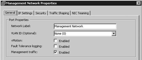
In some cases, a virtual machine cluster requires a private network for heartbeat communication. As is the case with VMware HA, you should isolate this traffic to ensure that the communication cannot be disrupted. As it will be a virtual machine or a physical node in a cluster sending this traffic, you should also isolate this traffic for other ESXi management traffic to ensure that a compromised virtual machine cannot then be used to attack your ESXi hosts. The virtual machine cluster may also require that you enable MAC address changes or forged transmits. If this is the case, you should set these options to Reject at the vSwitch level and then override them on virtual machine port groups specifically created for the virtual machines in the cluster.
The security concern with vMotion clusters is that information sent between hosts during a migration is sent in clear text. A person with access to the network would be able to capture this information flow and view the contents. The vMotion network should be isolated from your production network on an isolated segment. Only the ESXi hosts require a presence on the network. vCenter Server does not require an IP address on the vMotion. Ideally, this network should be nonroutable and configured within a separate vSwitch. If this is not possible, you should consider securing the vMotion network with a VLAN. You may also consider securing the vMotion network with IPSec, but this will require the use of IPv6 addresses, as IPSec is not supported for IPv4 addresses.
A repeated topic throughout this chapter has been the need to isolate network traffic to protect data and sensitive systems. With proper vSwitch design and the use of firewalls, you can ensure that potentially hostile traffic is kept away from more sensitive networks, such as those used for management or storage. Even within a single vSwitch, you can employ VLANs to segment traffic. But within a single vSwitch without VLANs or within a single VLAN on a vSwitch, it becomes more difficult to see and control the network interaction between virtual machines. Although you may be able to design your networking to ensure that DMZ virtual machines are not able to communicate with other network segments, a vSwitch cannot control traffic within the vSwitch. A virtual machine compromised within the DMZ would be isolated from the rest of your network, but capable of attacking other virtual machines in the same VLAN on the vSwitch.
To protect virtual machines in such a situation, you can employ firewall software within each affected virtual machine. Most operating systems now include a rudimentary firewall enabled by default, or you can employ a third-party solution. The VMware vShield family includes vShield App, which provides visibility into the network communication for your virtual machines and provides an application-aware firewall with deep packet inspection and connection control based on destination and source IP addresses. The vShield family also includes vShield Edge, which provides network perimeter security, and vShield Endpoint, which enables antivirus and anti-malware scanning of virtual machines from a hardened security appliance. As these solutions are hypervisor based, they are protected from attacks that would comprise the same type of solution operating as an agent service within the virtual machine.
When deployed within your environment, vShield App consists of the vShield Manager appliance, which provides the centralized management component for vShield. The vShield Manager communicates with vShield App appliance, which runs on each ESXi host that you intend to protect with vShield App. These components communicate with hosts and virtual machines through the vSphere API and are compatible with other VMware features such as vMotion and HA. vShield App integrates with vCenter Server and can be managed via a plug-in for the vSphere client.
To begin using vShield App, you can select vShield application on the Home screen when you’re connected to your vCenter Server Host. At the datacenter, cluster, and virtual machine levels, you can select the Flow Monitoring tab to display information about the network connections that are occurring at that level. Figure 7.35 displays the network traffic to a virtual machine by traffic type, application type, and source and destination IP address or MAC address. Traffic data can also be displayed in a chart format.
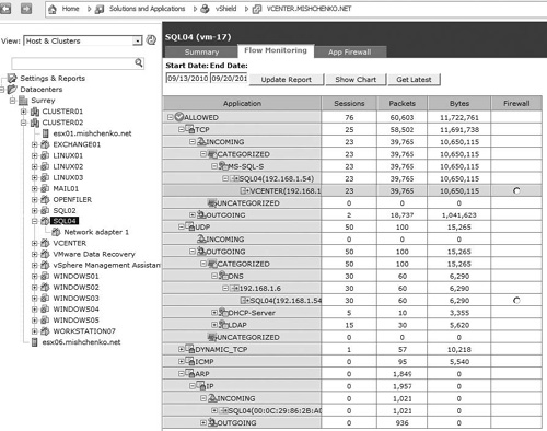
Once you have an understanding of your network traffic, you can begin to configure rules to manage traffic to and from your virtual machines. To ease management, you can group virtual NICs from many virtual machines into security groups and use those as the source or destination addresses in the rules that you create. Rules can be created at the datacenter, cluster, and network port group levels. To create a rule, you can select the App Firewall tab and then add a new entry specifying the source and destination addresses, ports, application, protocol, and action as shown in Figure 7.36. You can also create rules directly from the Flow Monitoring tab by clicking the radio button for a specific destination address.
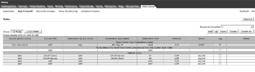
VMware ESXi was designed from the bottom up to provide a secure environment in which to host your virtual machines. The hypervisor, virtual machine, and virtual networking layers of ESXi enable virtual machines to operate in an isolated manner to ensure that malicious code within a virtual machine cannot be used to breach the hypervisor to attack the host or other virtual machines. You can employ resource limits and reservations further to ensure that virtual machines have adequate resources to perform.
This chapter has reviewed a number of tools that can be used to secure your environment. Traffic between your client PC and vCenter Server and between vCenter Server and ESXi hosts is secured with SSL certificates. With ESXi 4.1, you can further encrypt sensitive IPv6 traffic with IPSec. Careful planning and use of vSwitches and VLANs can ensure that your sensitive data and traffic are isolated from prying eyes. Update Manager and the vCLI provide the necessary tools to keep your hosts up to date on patches. You can employ permissions to secure vCenter Server and ensure that end users are limited in what tasks they can perform within your vSphere environment. vShield App provides the capability to protect individual virtual machines within a vSwitch and to gain a better view of the network traffic passing through your virtual networking infrastructure.
Security is a broad topic and certainly not one that can be conclusively discussed within a chapter, or even a single book for that matter. Nor is security a single step within your implementation plan, but rather an ongoing concern and something that requires periodic review. The vSphere Hardening Guide provides a great checklist to use, whether you’re planning your implementation or already using VMware ESXi. VMware’s Security Center can be found at http://www.vmware.com/security; it contains the latest security alerts, documentation, and tools.