
Now let’s take the next step and make the robot respond to your brain activity!
To connect the MindWave dongle directly to Arduino, we need to modify it a little bit. See Figure 2-28.
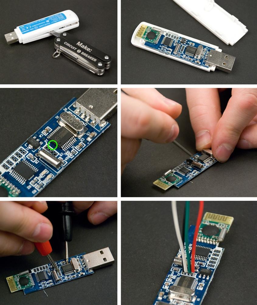
Figure 2-28. Hacking the dongle: remove the cover; destroy the connection marked with green circle; confirm you’ve broken the connection with multimeter; solder wires to dongle
Start by removing the dongle cover by lifting it from the seam with a screwdriver.
Use a razor knife to destroy the marked connections. The point of doing this is to disconnect the dongle USB port to enable you to read data from the RX and TX pins.
Use a multimeter with a conductivity setting to confirm that there is no connection between the chip pins 3 and 4 and the four connection pins shown in Figure 2-28.
Cut four different colored 8 cm wires. Solder the wires to the dongle as shown in Figure 2-29. Start with the red wire for the first pin, marked with “+” on the board. Solder the green wire to the dongle’s TX pin. Solder the white wire to the dongle’s RX pin. Finally, solder the black wire to the dongle’s GND. If you use a flux pen, it will make the process easier, because the old solder joints will flow more easily.

The NeuroSky USB dongle uses 3.3 volts to represent HIGH. Arduino uses 5 volts, 50% more. To avoid breaking the dongle, we must convert the level of voltage.
Most level converters are integrated circuits, black chips with circuits inside. Unfortunately, we never have the right chip at hand when we need it. In this project, you’ll build a level converter with just two resistors!
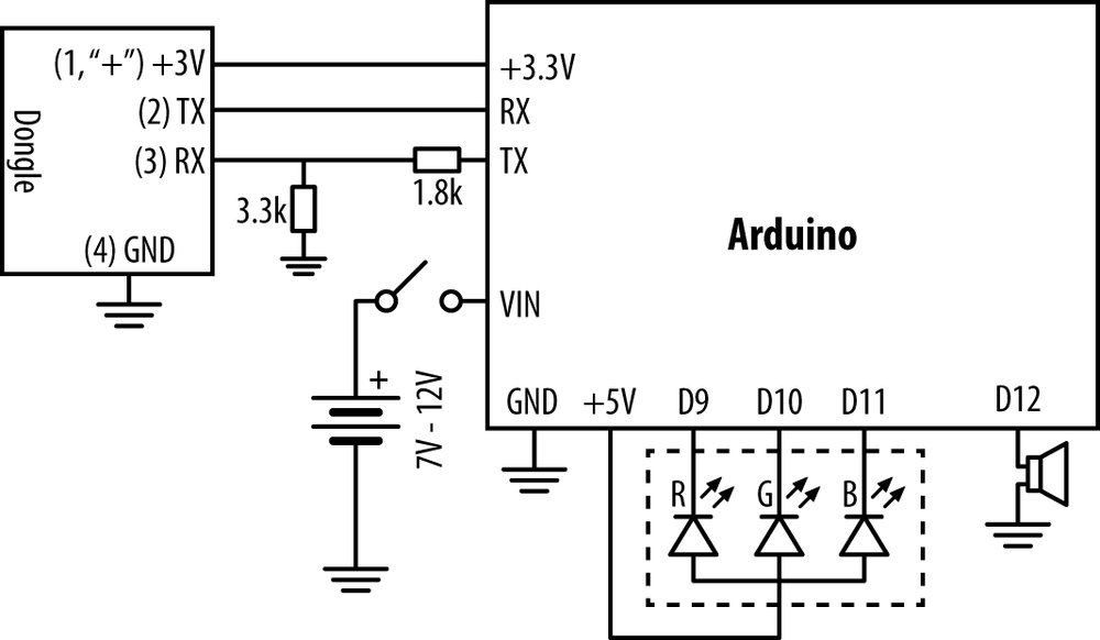
Three of the four dongle pins don’t need anything but jumper wire: +3.3V, GND, and TX. The resistors are needed for the dongle RX pin, so that it doesn’t get the full 5V from Arduino’s TX.
When connecting any two circuits, we want comparable voltage levels. When the ground level 0V is the same in both circuits, all voltage levels are comparable. Connect the dongle’s black GND wire to Arduino’s GND.
The dongle also needs power. Connect the red positive wire to Arduino’s 3.3 volt output (“3V3”).
Connect the dongle’s TX directly to Arduino’s RX (pin 0). When dongle TX (transmission) is sending the bit 0 (LOW), the voltage is 0V, same as Arduino LOW.
What about when the dongle’s TX sends bit 1 to Arduino RX? Surprisingly, no resistors are needed here. When dongle TX is sending the bit 1 (HIGH), the voltage is 3.3V. This is one-third less than Arduino’s 5V HIGH. But it’s still over half of 5V! As 3.3V is more than 2.5V (Arduino’s threshold), Arduino considers this HIGH. Because the voltage is lower than expected, nothing will get too hot.
Arduino’s TX sending 5V to a dongle pin made for 3.3V requires more tricks.
Connect Arduino TX (pin 1) with a 1.8 kOhm resistor to Dongle TX. Connect Dongle TX to GND with a 3.3 kOhm resistor.
Arduino sending bit 0 (LOW) is the simpler case. In the top of Figure 2-30, you can see dongle TX connected to 0V through both resistors. Obviously, it ends up in ground level, 0V.
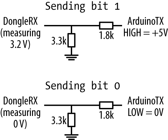
What about Arduino sending bit 1, HIGH? Here, the two resistors act as a voltage divider.
On the top, there is +5V. Then there are two resistors, and finally 0V. Between the two resistors, dongle RX measures voltage. According to Ohm’s law (U=IR), the voltage gradually reduces to 0V as you follow the resistors.
The total resistance is 1.8 kOhm + 3.3 kOhm = 5 kOhm. If you start from +5V and measure the voltage at 1.8 kOhm, the voltage is reduced by 36% (1.8 kOhm / 5 kOhm).
So 64% of 5 V voltage is left. It seems we’ve chosen the correct resistors, as 64% of 5 V is 3.2 V. This is almost the same as the target, dongle HIGH level 3.3 V.
Now you know the “two resistor level converter” trick.
Warning
We also had to see if the hacked dongle would work without a level converter. In our foolhardy tests, we noticed that NeuroSky dongle could take 5 volts—at least for a short while. However, we prefer to keep our components in reliable, stable condition. That’s why we normally use the level converter.
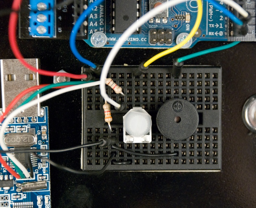
Connect your hacked dongle to Arduino. Connect the wires using the breadboard in your bot (Figure 2-31) according to the circuit diagram (Figure 2-32).
Upload helloattention.pde and try it out.
Try controlling the LED with your mind:
- Turn off both the NeuroSky EEG headband and Arduino.
- Turn on Arduino. The Main LED turns green.
- Turn on the NeuroSky EEG headband. Tiny LEDs in the NeuroSky headband and dongle are red. When the wireless connection is working, the tiny LEDs turn blue. When the robot can get information from the headband, the main LED turns yellow.
- Place the headband on your head. When the robot gets the signal, the main LED shows your attention. The main LED will be a color from blue to red.
As you focus, the main LED will turn red. When your mind wanders and attention goes down, the main LED will turn blue. In between, it’s indigo, a mixture of blue and red.
Got helloattention working? Great! Now you can start building your own attention-controlled projects.
// helloattention.pde - Show attention level (EEG) with LED color.
// (c) Kimmo Karvinen & Tero Karvinen http://MindControl.BotBook.com
/* Disconnect TX and RX jump wires from Arduino when uploading from IDE.
Turn robot on, then in a couple of seconds turn headband on. */
const int redPin = 9;
const int greenPin = 10;
const int bluePin = 11;
const int tinyLedPin = 13;
const int speakerPin = 12;
int tinyLedState = HIGH;
void setup()
{
pinMode(redPin, OUTPUT);
pinMode(greenPin, OUTPUT);
pinMode(bluePin, OUTPUT);
pinMode(tinyLedPin, OUTPUT);
pinMode(speakerPin, OUTPUT);
Serial.begin(115200); // bit/s //  connectHeadset(); //
  }
void loop()
{
float att = getAttention(); //
}
void loop()
{
float att = getAttention(); //  if (att > 0) //
  setBlueToRed(att);
toggleTinyLed(); //
setBlueToRed(att);
toggleTinyLed(); //  }
/*** Headset ***/
void connectHeadset()
{
setGreen();
delay(3000);
Serial.write(0xc2); //
}
/*** Headset ***/
void connectHeadset()
{
setGreen();
delay(3000);
Serial.write(0xc2); //  setWhite();
}
byte readOneByte()
{
while (!Serial.available()) { //
setWhite();
}
byte readOneByte()
{
while (!Serial.available()) { //  delay(5); // ms
};
return Serial.read();
}
float getAttention()
{ // return attention percent (0.0 to 1.0)
// negative (-1, -2...) for error
byte generatedChecksum = 0; //
delay(5); // ms
};
return Serial.read();
}
float getAttention()
{ // return attention percent (0.0 to 1.0)
// negative (-1, -2...) for error
byte generatedChecksum = 0; //  byte checksum = 0;
int payloadLength = 0;
byte payloadData[64] = {
0
};
int poorQuality = 0;
float attention = 0;
Serial.flush(); // prevent serial buffer from filling up //
byte checksum = 0;
int payloadLength = 0;
byte payloadData[64] = {
0
};
int poorQuality = 0;
float attention = 0;
Serial.flush(); // prevent serial buffer from filling up //  /* Sync */
if (170 != readOneByte()) return -1; //
/* Sync */
if (170 != readOneByte()) return -1; //  if (170 != readOneByte()) return -1;
/* Length */
payloadLength = readOneByte();
if (payloadLength > 169) return -2; //
if (170 != readOneByte()) return -1;
/* Length */
payloadLength = readOneByte();
if (payloadLength > 169) return -2; //  /* Checksum */
generatedChecksum = 0;
for (int i = 0; i < payloadLength; i++) { //
/* Checksum */
generatedChecksum = 0;
for (int i = 0; i < payloadLength; i++) { //  // Read payload into array:
payloadData[i] = readOneByte();
generatedChecksum += payloadData[i];
}
generatedChecksum = 255 - generatedChecksum;
checksum = readOneByte();
if (checksum != generatedChecksum) return -3; //
// Read payload into array:
payloadData[i] = readOneByte();
generatedChecksum += payloadData[i];
}
generatedChecksum = 255 - generatedChecksum;
checksum = readOneByte();
if (checksum != generatedChecksum) return -3; //  /* Payload */
for (int i = 0; i < payloadLength; i++) { //
/* Payload */
for (int i = 0; i < payloadLength; i++) { //  switch (payloadData[i]) {
case 0xD0:
sayHeadsetConnected();
break;
case 4: //
switch (payloadData[i]) {
case 0xD0:
sayHeadsetConnected();
break;
case 4: //  i++; // (16)
attention = payloadData[i]; // (17)
break;
case 2:
i++;
poorQuality = payloadData[i];
if (200 == poorQuality) {
setYellow(); // (18)
return -4;
}
break;
case 0xD1: // Headset Not Found
case 0xD2: // Headset Disconnected
case 0xD3: // Request Denied
case -70:
wave(speakerPin, 900, 500);
setWhite();
return -5;
break;
case 0x80: // skip RAW // (19)
i = i + 3;
break;
case 0x83: // skip ASIC_EEG_POWER
i = i + 25;
break;
} // switch
} // for
return (float)attention / 100; // (20)
}
/*** Outputs ***/
void setBlueToRed(float redPercent)
{
int red = redPercent * 255;
int blue = (1 - redPercent) * 255;
setColor(red, 0, blue);
}
void setGreen()
{
setColor(0, 255, 0);
}
void setYellow()
{
setColor(255, 255, 0);
}
void setWhite()
{
setColor(100, 100, 100);
}
void sayHeadsetConnected()
{
wave(speakerPin, 440, 40);
delay(25);
wave(speakerPin, 300, 20);
wave(speakerPin, 540, 40);
delay(25);
wave(speakerPin, 440, 20);
wave(speakerPin, 640, 40);
delay(25);
wave(speakerPin, 540, 40);
delay(25);
}
void setColor(int red, int green, int blue)
{
analogWrite(redPin, 255 - red);
analogWrite(greenPin, 255 - green);
analogWrite(bluePin, 255 - blue);
}
void toggleTinyLed()
{
tinyLedState = !tinyLedState;
digitalWrite(tinyLedPin, tinyLedState);
}
void wave(int pin, float frequency, int duration)
{
float period = 1 / frequency * 1000 * 1000; // microseconds
long int startTime = millis();
while (millis() - startTime < duration) {
digitalWrite(pin, HIGH);
delayMicroseconds(period / 2);
digitalWrite(pin, LOW);
delayMicroseconds(period / 2);
}
}
i++; // (16)
attention = payloadData[i]; // (17)
break;
case 2:
i++;
poorQuality = payloadData[i];
if (200 == poorQuality) {
setYellow(); // (18)
return -4;
}
break;
case 0xD1: // Headset Not Found
case 0xD2: // Headset Disconnected
case 0xD3: // Request Denied
case -70:
wave(speakerPin, 900, 500);
setWhite();
return -5;
break;
case 0x80: // skip RAW // (19)
i = i + 3;
break;
case 0x83: // skip ASIC_EEG_POWER
i = i + 25;
break;
} // switch
} // for
return (float)attention / 100; // (20)
}
/*** Outputs ***/
void setBlueToRed(float redPercent)
{
int red = redPercent * 255;
int blue = (1 - redPercent) * 255;
setColor(red, 0, blue);
}
void setGreen()
{
setColor(0, 255, 0);
}
void setYellow()
{
setColor(255, 255, 0);
}
void setWhite()
{
setColor(100, 100, 100);
}
void sayHeadsetConnected()
{
wave(speakerPin, 440, 40);
delay(25);
wave(speakerPin, 300, 20);
wave(speakerPin, 540, 40);
delay(25);
wave(speakerPin, 440, 20);
wave(speakerPin, 640, 40);
delay(25);
wave(speakerPin, 540, 40);
delay(25);
}
void setColor(int red, int green, int blue)
{
analogWrite(redPin, 255 - red);
analogWrite(greenPin, 255 - green);
analogWrite(bluePin, 255 - blue);
}
void toggleTinyLed()
{
tinyLedState = !tinyLedState;
digitalWrite(tinyLedPin, tinyLedState);
}
void wave(int pin, float frequency, int duration)
{
float period = 1 / frequency * 1000 * 1000; // microseconds
long int startTime = millis();
while (millis() - startTime < duration) {
digitalWrite(pin, HIGH);
delayMicroseconds(period / 2);
digitalWrite(pin, LOW);
delayMicroseconds(period / 2);
}
}-
Communication with the dongle is very fast, 115.2 kbit/s. It’s always a good idea to specify the units in your comments.
-
At very beginning, we set the main LED to green to ask the user to turn on the headset.
-
getAttention()is the heart of the program. It returns attention as a percentage, from 0.0 (0%) to 1.0 (100%).-
We only show attention with the main LED if there is some. Otherwise, we leave the main LED set to whatever color it is currently set to: green, white, or yellow. Function
getAttention()could have set it to one of the following: green (turn on headband), white (no headband-dongle-arduino connection), or yellow (no EEG, even though headband-dongle-arduino connection works).-
We blink Arduino’s surface mounted LED (pin 13) on every iteration of
loop()to confirm that we’re still running. Normally, the blinking is so fast it looks like flicker or almost as though the LED was continuously on.-
0xc2 is instruction for the dongle to try connecting to any headband it can find. This has to happen briefly after the headband is turned on, because the headband is trying to get a connection, too.
-
Wait until a byte comes from serial. If this means forever, then so be it. But
readOneByte()is guaranteed to return a byte. As a loop with no delay takes infinite capacity of any single core CPU, we add a very short wait in the loop.-
Variables are local, so we don’t have to care about those when outside
getAttention().-
If the serial buffer fills, Arduino seems to crash. With
flush(), we ignore all data currently in the serial buffer. Losing this data is not critical, so long as we callgetAttention()often.-
Return an error if we don’t see the sync sequence 170 170. The
returnstatement ends this function. This is much better than putting the meat of the function inside multiple +if+s.-
The maximum length is from the NeuroSky reference documentation.
-
Both calculate the checksum and read payload into the array
payloadData[].-
Compare calculated checksum to the number that came with the packet. The checksum calculation algorithm is from NeuroSky documentation.
-
Iterate through each byte in the
payloadData[]array. Here,iis the number of payload bytes we have processed.-
In this case, the payload indicated that it’s of the field type (4 means attention).
- (16)
We increment the counter
ihere, too. It would be more common to incrementiin just the loop headerfor(...; i++). But in the NeuroSky protocol, different data types have different lengths, so incrementingihere gives the simplest solution.- (17)
As it’s obvious from here that we’re reading attention, no comment about the meaning of field type 4 is needed.
- (18)
This indicates a problem to the user by changing the main LED color. It will be left in place while the problem persists, because
loop()only changes color ifattention > 0.- (19)
Even if long values are not interesting to us, we have to skip them. A comment is necessary, because the meaning is not obvious from the code.
- (20)
Floating point numbers from 0.0 to 1.0 are practical for percentages. For example, you can multiply by a floating point percentage value. We use an explicit cast to float to ensure we get a floating point value.
Now that it works, would you like to know how? Or if it doesn’t work yet, would you like to know the details so you can fix it?
Warning
As of Arduino 1.0, which was still in testing at the time of this writing, the behavior of flush() is changing significantly. If you are using Arduino 1.0, check the book’s catalog page (see How to Contact Us) for new example code, or visit the authors’ site at http://botbook.com.
How do you begin when faced with an unknown protocol? We did some Googling, and found that the NeuroSky reference documentation and more was available on the NeuroSky website. For example, see “MindWave and Arduino” (NeuroSky 2011), “MindSet Communications Protocol” (NeuroSky 2010), and “arduino_tutorial” in the NeuroSky wiki (http://developer.neurosky.com/docs/doku.php?id=start).
The NeuroSky dongle communicates over the serial port. We have wires going to Arduino RX and TX.
Every packet is of this format: sync (170 170), payload length, payload, and a checksum (see Table 2-1).
Table 2-1. NeuroSky packet
| Meaning | Example | Comment |
|---|---|---|
Sync | 170 170 | Always the same |
Payload length | 4 | Most common length in this project |
Payload | 4 86 | 4 attention, value 86/100 = 86% |
Payload cont. | 2 0 | 2 poor signal, value 0 signal OK |
Checksum | 163 | 255–(sum of each payload byte) |
Even though the reference documentation saved us the tedious work of reverse-engineering the protocol, there were surprises around the corner. Coping with serial buffer overflow, long delays caused by moving parts, and doing voltage level changes without additional circuits were problems to solve.
NeuroSky, the manufacturer of MindWave, provides excellent documentation. See “MindSet Communications Protocol” and “MindWave Dongle Communications Protocol.”
Some code samples on the Web use everyday decimal format (170), but some use hexadecimal (0xaa or just AA). We’ve compiled a list of the most common code numbers (Table 2-2).
You can also convert numbers with Python. Just start Python at the command line and you’ll get an interactive console where you can type things like hex(170) or 0xaa. Or you can use http://www.wolframalpha.com or Google. Most of the NeuroSky protocol control characters we use are outside ASCII. The last ASCII printable character is 126 tilde ~; the last ASCII character is 127 DEL.