
![]()
Smart Home Enablers
The future almost never turns out how we think it will. The much parodied “home of the future” concepts of yesteryear all had a central controlling computer at their core. Like a spider at the center of an electronic web, this computer called all the shots when it came to controlling the automated functions within the home. It was this behemoth that controlled every aspect of the automated serving of the dog’s dinner or drawing those famous motorized curtains when night fell.
In early versions of the concept, it was a basement-filling box with numerous flashing lights and hundreds of chattering relays inside it. It did, of course, have a teletype that slowly chunkered out its proclamations to the humans that notionally controlled it. Yes, home automation was the future. No doubt about it!
In later versions of the vision, the control entity became an additional desktop machine that sat alongside the existing one (or was locked away in a closet, presumably building up the heat that caused its own demise!).
In more recent times, the whole concept has undergone a rebranding. Most people working in this field now tend to use the term “Smart Home.” I think that, in part, this new term was taken up enthusiastically because for many people the older term “home automation” carried the baggage of years of failed promise. However, it’s also in recognition of that fact that, since the advent of cheap microprocessors and more especially MCUs, it’s now possible to place numerous points of “intelligence” around the home. A central entity may still exist in some versions of the concept, but its role is now much more as a coordinator and facilities provider than as a direct controller.
Is Your Home Smart?
The term “Smart Home” is an imprecise one and is thus open to much abuse. Look around the modern home, look around YOUR home, is it smart? Do you find these things?
- A kettle that turns itself off when the water inside it boils.
- A heating controller that comes on at a preset time and goes off at a preset time, which you can vary by day of the week.
- A cable or satellite TV box that you can program to automatically record the shows and movies that you like—and maybe even suggest additional shows that might appeal to you.
- A motion-triggered light for that dark stairway.
- A telephone answering device.
- An oven, washing machine, or dishwasher with a timer that you can preset to come on and go off at times you preselect.
- A doorbell device that can play any one of 20 preset tunes that you can select.
- Remotely controlled power sockets that you can activate with a small remote.
- A wireless network that allows you to hop onto the Internet on any one of a dozen different kinds of devices from anywhere in your home.
- A computer with a library of music, video, and family photos on it.
You probably do find many of these items—and other things besides. So is yours a Smart Home already? Twenty-five years ago, people would have probably said that, yes, these things did indeed add up to a Smart Home! But look again at the list above. Most of these things have embedded in them islands of intelligence or automation, but do they talk to one another? Do they make one another aware of what they are doing? Probably not. This goes to the core of why the Smart Home dream has failed to deliver its full potential. In short, it’s a common or garden communication problem!
A challenge! Look around and try to buy the following example products off the shelf:
- A home heating system controller that can connect to your wireless network and be commanded from your Home Theatre PC or by you from your desk at work via the Internet.
- A music player for your car that you can fill up with music or speech content wirelessly from your home music library via Wi-Fi.
- A doorbell that “knows” there is nobody home and therefore plays randomly spaced barking dog sounds if the doorbell is rung.
Yes, all of these things can be done and, yes, for serious money you can even buy some of them from high-end specialist vendors! However, due to their high prices, they are just techno-toys for well-heeled tech enthusiasts. For the Smart Home concept to actually succeed on a large scale, something fundamental has to change to allow the whole thing to go commodity. That thing can be summed up in one word: standards.
Very few of the available Smart Home components can talk directly to one another, and no major manufacturers of household goods has been persuaded of the merit of building in support for one of the putative standards (for example, X.10, which is the closest thing to a predominant standard, especially in the US) for their mainstream products. With almost all household goods now having one or more MCUs at their heart, you would think that it would be pretty easy to make almost any household device talk TCP/IP in some way, but no, seems like there’s no demand for it.
Well, that’s demonstrably not true. The enthusiastic adoption over the last 25 years of the kind of devices listed above conclusively proves that we really do want intelligent devices doing things for us in our homes. But we want the kind of set-and-forget simplicity that we have become accustomed to from computers and computer networks. Thus Smart Home products would have to abandon proprietary approaches in hardware and do other things such as perhaps adopting standard object models (see Chapter 6 of Practical AVR Microcontrollers [Apress, 2012]). In other words, the Smart Home industry needs to backtrack and learn from the IT industry, which realized many years ago that if you make your hardware and software interoperate as seamlessly as possible, pretty much everybody wins. The idea that the connected, automated, or Smart Home is going to become commonplace while there is no universal plug and play compatibility between any intelligent device that you might care to buy is delusional.
In a very selfish sense, the fact that you can’t buy cooperating Smart Home components at your local corner store is good news for the readers of this book! It means that the MCU enthusiast holds trump cards in his or her hand when it comes to Smart Home making. You have the ability to make your own smart devices and you probably have the knowledge to engineer interfaces to allow at least some of those stubbornly isolationist smart devices referred to above to interoperate with one another. This chapter explores this area in a little bit of detail. Of course, there are whole books on the subject of home automation and the Smart Home, so in just this one section of this one book we can only skim the surface by looking at a few techniques to make communication easier, but let’s make a start!
Hacking is the name of the game when it comes to compensating for the lack of Smart Home equipment standards. All consumer products have a user interface of some sort; if you can find out how that user interface works, then you can use your MCU to pretend to be a real user. Let’s start with a prime example: a remote controlled power socket.
It’s very easy now to buy power sockets that you can switch on and off with a supplied remote control. How these look obviously varies from country to country since power outlet formats vary so much. Most DIY stores stock these products in some format and of course you can also get them from the usual electronics outlets.
- www.homedepot.com (US), search for product number 100654961 (indoor remote kit)
- www.maplin.co.uk (UK), stock code N79KA (3-pack remote control sockets)
These products send a coded signal from a handset to one or more power socket extensions to tell them to switch on or off. Usually you can buy these in single, three, or sometimes sets of five.
For your purposes, the main limitation of these things is that they only let you control the socket on/off state via the supplied remote control. There is (of course) no other interface; you can’t command it from your Wi-Fi network or from the USB port of your PC or anything as useful as that!
So, how would you go about incorporating these sorts of products in your Smart Home setup? Say you wanted to be able to command one of these devices from a desktop computer via a USB port; how might you do that? There are two ways: a mainly software way and a mainly hardware way.
The software way consists of hooking up an appropriate type of electronic “ear” (sensor) to your AVR to allow it to capture the signal sent for each keypress on the remote. You then use software to record these signals into a small digital library. You can then replay the required keypress on the appropriate radio frequency when you want to simulate a keypress.1 This approach works in much the same way as if you were recording each of the tones from a telephone keypad and then playing them back in the required order into the phone’s microphone to make a phone call. There are various Arduino libraries (e.g., the Home Easy library) to help you go down this route, plus numerous online and print publication articles about how to go about capturing keypresses, etc.
You’ll find that the kind of remote controls of interest in this context operate around the 315MHz or 433MHz bands depending on where in the world you are located. The remote control for your product should have a label on it showing exactly what frequency band it uses.
The software approach can be a good one. There’s almost no hardware cost involved and you don’t need to break open the original remote control hardware to make it work. The downside is that it won’t work with some more advanced products because they use an encryption algorithm to ensure that their signals are unique each time. That means that recording what they “say” during one session won’t do you any good because what they say during the next session will be different and what you have captured will be stale and not work. With these kinds of products, you must “train” senders and receivers to recognize one another right after their first power up. If the products you are using don’t need any training, then you’re probably okay to go the software route!
The hardware approach is actually very simple but it will invalidate your warranty on the product! Just to be clear, I’m not kidding; making the modification to be described here will definitely invalidate any warranty you may have on the product. So, work carefully and use anti-static precautions when handling the electronic parts.
All you need to do is take apart your remote control and use the contacts of a small relay that your software will pulse to make the relay contacts bridge the same contacts that the buttons on the remote control use. You’ll need to use a driver to enable your MCU to drive the relay. You could use a 2803a chip (as you used in various other projects) to activate your relay. Don’t forget to use the snubber diodes inside the 2803a to deal with the back-EMF. If you need to refresh your memory about the 2803a and snubber diodes, take a look at Figure 4-21 in Chapter 4 of Practical AVR Microcontrollers (Apress, 2012).
Often there’s just one little recessed screw to allow you to disassemble the remote control. But sometimes the hardest part is getting the remote control apart! Some of these products clip-fit together; you’ll find a tiny slot where you can insert a very small screwdriver to prise the top and bottom of the case apart. Other times there is a small but continuous groove all the way around the product; if you get a small flat blade screwdriver and carefully run it around the groove, pressing down fairly hard, you will release some little tabs inside it that hold the two halves of the product shell together. Careful how you do this; keep your fingers well out of the way!
Other times the manufacturers hide the fixing screw under a label. If you suspect this is how your remote control is made, get the handle end of your screwdriver and rub it firmly around the label face. Then, hold the label up to a bright light and you should be able to see the indent of the screwhole. Pierce the label at that point and you should be able to disassemble.
Once you have your remote control apart, you should easily be able to see how the buttons, when pressed, bridge the sets of contacts. It’s up to you to decide how many buttons you want to extend out of the remote, but it’s usually a very simple job to add wires to the contact points and bring them out to the contacts of a small relay that your MCU can control. The resulting solution may not be especially elegant, but it will allow your MCU to easily control main devices in a very safe way. Usually you can hide away the wired-up remote control.
On the Radio: The Un-wired Home
As stated earlier, we can’t address the massive subject of the Smart Home in a few pages of one book, but one area that seems worth spending some pages exploring—and looking at just one pragmatic solution—is the crucial area of communications.
One particular barrier to Smart Home communication is wiring. Unless you’re lucky enough to be closely involved with planning, building, or completely gutting and renovating your home, running a cable to the location of each and every little device that you may want to participate in your Smart Home is quite an undertaking!
Just thinking about the AVR level of Smart Home making: you’d need to have everything from a smart bell push for the front door to a smart door sensor, temperature sensors, motion sensors, light sensors, smart locks, entry keypads, lighting controllers… the list is a potentially very long one, even before you start adding your higher-end multimedia terminals, digital music and video streaming, and so on. Are you really going to run a CAT5 or CAT6 cable for each one of these things?
There are, of course, many alternatives to running wires to each and every little AVR powered device around your Smart Home.
- Wi-Fi—802.11b/g: This is superficially attractive because you are quite likely to have a Wi-Fi network in your home already, so what could be neater than having your Smart Home devices tap into it? Logistically true, but financially flawed. Look at price of a Wi-Fi module that works with (for example) an Arduino. You’ll be doing well if you can find one for less than $40 US, and it won’t even be a complete solution; you’ll need to add some extra stuff to make it actually work with your AVR. Add the cost of your AVR (or an Arduino, if you go that route). Multiply that by the number you will require and… well, the numbers don’t look attractive.
- There are many products available now that let you make Ethernet network connections through the mains wiring of your house; this is often called powerline networking. These products work really well in most situations (though they are not legal to use in all countries as yet, so do check the local legalities). But again, explore the cost-per node: add up the cost of a mains network interface and the Ethernet module you will need to allow your MCU to be an Ethernet end node. Multiply the cost per node by the number of Smart Home peripherals you think you might need and see if your eyes don’t water! By my reckoning you’re looking at about $60 per node, minimum, at the time of writing!
- Zigbee is another wireless networking standard that is much vaunted by the Smart Home movement, but again, unless product prices fall (another case of a minimum $50 per viable node at the time of writing), this is not really not going to find its way into high-volume consumer products any time soon.
- There are other alternatives such as Bluetooth, which is more viable financially, coming in at about half the price of the solutions above. However, anything using a Bluetooth solution has to go through the overhead (and delay) of pairing at start-up and handling connection drops and so on.
- There are other basic ways to do certain kinds of wireless connections and these are far lower cost. We’ll take a look at one of these options in the “Low-Cost Wireless Communication” section later in this chapter.
Wiring Up
So, clearly the wireless route has the potential to be fairly high cost. However, you may think that is a price worth paying in order to save having to run (and live with) all that wiring. Returning to the subject of wiring, where exactly is the problem?
Many Smart Home setups feature a radial wiring plan. In other words, there is some central point to which each and every cable goes back (see Figure 6-1). This central point is often a wiring shelf in a closet or (in a large home) a utility room containing a wiring hub in a floor standing cabinet. The nodes of the network derive their power from the nearest mains outlet.
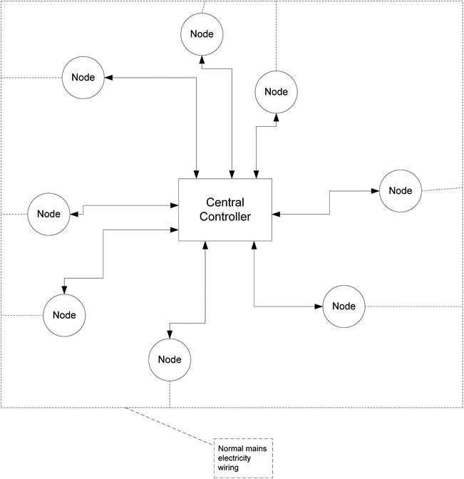
Figure 6-1. Smart Home radial connection—central control
Nodes can be anything from a desktop computer to a door sensor. This radial wiring approach goes back to the original notion of having a single controlling entity at a single point in the Smart Home. As outlined earlier, it goes all the way back to the days when the cost of the controlling central computer was the biggest price ticket item in the whole enterprise, back to the days when the control computer was the single most unique and complex item in the whole setup.
However, thanks in large measure to the MCU, the radial wiring approach now has competition; as described earlier in this chapter, the intelligence in a modern setup can be much more distributed. In this alternative model, there doesn’t need to be a central point. There is simply a network connection linking all points in some way. It may be a simple daisy chain, as in Figure 6-2. In this model, the central controller has been simplified to a resource server. For example, it may simply issue network addresses or it may offer hard drive storage for nodes to send logging data to.

Figure 6-2. Smart Home daisy chain wiring
A more mixed scheme, as shown in Figure 6-3, might also be used. This is no longer a daisy chain; it is a fairly random arrangement with the only requirement being that all nodes on the network can “hear” one another in some way. In this model of operation, nodes can have the ability to generate events and to consume events and autonomously act upon them (again, see the discussion in Chapter 6 of Practical AVR Microcontrollers [Apress, 2012]).
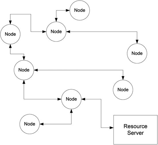
Figure 6-3. Smart Home—mixed topology
Back to Basics
Going back to basics, what you need is, in many cases, incredibly simple. If you referred to Chapter 6 of Practical AVR Microcontrollers (Apress, 2012), you saw that, with proper and tight design of your communications, messages can be very compact. For example, in the SHOM (Smart Home Object Model) imagineered there,2 the 5-byte sequence shown in the following table conveys all the information that is required for a sensor node to communicate its state:
|
Byte # |
Means |
|
1 |
1 = Fittings |
|
2 |
5 = Windows |
|
3 |
1 = Sensors |
|
4 |
8 = Window number 8 (rear, ground floor, kitchen) |
|
5 |
2 = Event code (might mean has gone from closed state to open state) |
For conveying something so small, some of the connection methods listed above (and their associated costs) somehow seem like using the proverbial sledgehammer to crack a nut! Of course, as you saw in “Digitally Speaking” you’d have to add some kind of jacket around the basic 5-byte packet plus a header and some checksum protection. Even so, the whole message in this example would be unlikely to be more than 15 bytes long.
In fact, in a network like the one in Figure 6-3, many of the nodes will be very trivial ones, such as a window sensor, a light level detector, a doorbell button, a phone ring detector, etc. These kinds of nodes are very easily implemented using a very cheap, low-end AVR; it doesn’t have to offer a lot of I/O lines and it doesn’t need a lot of memory. Each one only needs to do the following things:
- Interface with a sensing or switching element (for example, the window open sensor).
- Have the ability to be programmed with an ID. Going back to the SHOM example, it needs to know that it is a node of type FittingsWindowsSensor, it is sensing the open/closed state of window number 8, and the event code to generate for any given sequence of sensor inputs.
- It needs to be given some kind of interface to allow it to participate in the local network.
All except the last item on this list can easily be met by using a low-end 8-pin AVR costing just a couple of dollars, but what about that last item?
Low-Cost Wireless Communication
If you want to embrace the idea of having a Smart Home in which you can embed intelligence everywhere at an affordable price, you need to think pragmatically. There are low-cost wireless products that you can use; they can be bought (from Asian vendors) for as little as $5 for a transmitter module and a receiver module. These are usually sold as “xxMHz receiver transmitter modules” by various electronics sites (where xx is usually 433 in much of Europe and 315 or 434 in North America).
- www.sparkfun.com/products/10534 (US) Transmitter
- www.sparkfun.com/products/10532 (US) Receiver
- www.techsupplies.co.uk (UK) (search for RFA001 and related items)
Many companies seem to make these. Two typical ones that I have used are shown in Figure 6-4. The transmitter module is on the right and it has the following three pins:
- +Vcc (typically between 4.5 and 9 Volts)
- Ground
- TXdata (a logic-compatible input)
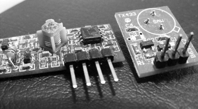
Figure 6-4. Low-cost short range radio modules
The receiver is on the left and it has four pins, though only three are actually used. These carry
- +Vcc
- Ground
- RXdata (a logic-compatible output)
Both modules easily plug into a breadboard (though you may need to add some header pins).
Make sure that the modules you buy have logic level (TTL/CMOS) compatible inputs and outputs and can operate on +5Volts. Most such products seem to meet these requirements, but do check before buying. The modules require the addition of an antenna (see bullet point, below).
The essential idea is that you connect the serial port pins (transmit and receive) of the AVR to the radio modules and, using a port speed of 2400 baud (as opposed to the more usual 9600), you can exchange data across the resulting link. There are some important things to be aware of when using these modules:
- The modules MUST use a wavelength (e.g., 433MHz) that is license exempt in your geography. Your vendor can advise. Do not import modules from another country and assume they will be okay; license-exempt frequencies vary from place to place.
- The communication they provide is usable over only very short distances inside a home. About 20 feet (approx. 6 meters) seems to be an optimum (see below) using just a wire antenna. If you are willing to use a more elaborate antenna, you will get a far greater range but at more cost and trouble.
- They are in no sense intelligent. They do no packetization of the data to be sent; neither do they offer guaranteed delivery of that data or any error checking.
- They are not secure. Anyone sitting outside your home with sufficiently sensitive listening equipment could listen in to the traffic passing between these modules.
Looking at the kinds of applications you have in mind, the second and third items on this list are not necessarily big problems. If you can install a small number of wired hubs around the home (hidden in ceiling voids, crawl spaces, closets, etc.), those can act as signal relays. Then you only require short distance transmission to the nearest hub node. Because they only communicate occasionally, many wireless nodes can talk to a single hub. As for these being very dumb devices, you’re using an AVR in each end node and the intelligence can be built into the software of that.
As for the final item on the list, it’s true that anybody with a malicious intent and the right knowledge could start commanding your Smart Home to do some wacky stuff! So you do need to be aware of this when deciding when to use this approach and when to use more expensive ones. You’ll look at this in more detail in a short while.
Security is always an issue, and sadly, most wireless security protocols seem to get cracked (a quick Google search can verify this), so you should never assume that you can attain total security in wireless communications of any kind. Later in this chapter you’ll look at some more detailed cases for deciding whether to use low-cost wireless or not.
Smart Home Using a Mixed Network
What would a Smart Home network built using a mix of short range radio modules and wired hubs look like? It might look something like the diagram in Figure 6-5, in which you might still have your resource server (though it’s not mandatory) and a handful of wired hub nodes. Each wired node acts as a highly localized area hub, located near a cluster of wireless nodes. If the diagram brings to your mind a picture of many desktop-grade machines scattered around the home, jammed into closets, hidden under beds, or perched precariously on top of bookshelves, forget it! It’s more likely that
- The hub nodes would be something like an Arduino in a box, equipped with an Ethernet CAT6 (or perhaps the compatible, but older CAT5) interface and with a low-cost radio transmitter and receiver attached to its serial port. Alternatively, it might be a naked AVR (see Chapter 3 of Practical AVR Microcontrollers [Apress, 2012]!) board of your own devising.
- The wireless nodes would be controlled by a very low-end AVR chip with a low cost radio module attached, built into something no larger than the size of a couple of matchboxes. Possibly it would be battery powered or it might just need to plug into a USB power adaptor to any nearby mains power socket.
- The resource server could be an old desktop machine or laptop.
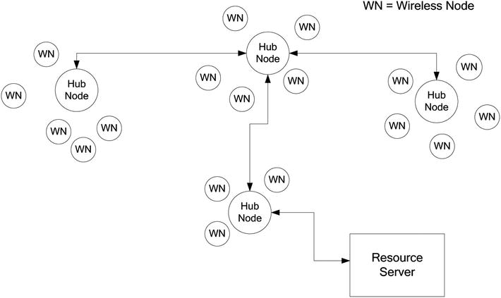
Figure 6-5. Mixed network, wired and wireless
The wired network might be a completely separate one from the one you use for your desktop machines, or it might be the same one. If it were separate, the resource server could be set to route traffic between the two LANs.
The possibility (make that, probability!) that some of the data that these kinds of nodes send will be lost, or could be heard by a third party, is a deciding factor in whether you use a wireless or wired node.3
The following are some examples of where datapath reliability or security is important and where it is not:
- Case 1: A movement sensor that is intended to trigger some lights might be connected over a short-distance radio link. If a person enters the room, the sensor is triggered and the node to which the sensor is attached broadcasts a message on the network, indicating that this movement trigger has been activated. Another node that is monitoring for such event notifications is supposed to turn the light on, but it never “sees” the movement sensor event because the network is busy. The person who triggered the light and has gotten used to the lights turning on when she enters the room simply does what we all do in such circumstances, she waves her arms around. This time the system works and the lights come on; no big deal, just so long as it doesn’t happen every time.
- Case 2: A flame sensor is connected over a short-distance wireless link. The flame sensor senses a flame: a log has spilled out of the open fire and onto a carpet. The node to which the sensor is connected sends out a message that is supposed to raise the alarm, but the data packet it sends never makes it. A sprinkler system controller is listening for flame sensor triggers but never sees the alarm. Bad news!
- Case 3: A door entry system that allows a code to be entered on a keypad and then sends the entered code to a superior system via radio; it receives back an “Open” or “Don’t Open” response.
So, in the first case, you don’t really care if data is lost because the consequences are pretty trivial—just a minor temporary annoyance. However, in the second case, you do care a lot and that node should never have been made wireless! Case 3 should never be wireless because a listener could easily intercept the keycode they need to be able to get through the door.
In summary, if it’s just a matter of somebody knowing when your door opens or closes, do you care? If they start commanding your feature lights to go on and off, well, it’s pretty easy to disable that feature until they get tired of the game. However, for other things, this low-cost approach is not sensible to use and you will have to use a more expensive setup. Yes, this kind of wireless connection has limitations, but it is a very useful and low-cost way to avoiding running wires around your home for a significant number of purposes, especially for simple sensors or lighting control.
Taking the earlier project of the waterfall lights (the passageway lighting system) as an example, if you added a wireless sender module to that, it could send out a log of its activations and status. If you added a send-and-receive module, it could receive commands to switch on and receive updates, for example to the length of time it stayed on, based on an analysis of sensor log data collected over a period of time. If you had a house security controller, the waterfall light could receive “nobody home mode” messages that would make it ignore any sensor activations that might be made by the dog or cat wandering around.
In short, if the less critical elements of a Smart Home setup could be implemented with a cheap and easy way to allow it to contribute information into a Smart Home network, then many things would change! This approach is very much in line with initiatives like VSCP (Very Simple Control Protocol), which aim to allow cheap and simple Smart Home implementations by simplifying and commoditizing the design and topology involved.
A Simple HomeHelp Protocol
As outlined in the previous section, the low-cost radio modules do not have any embedded intelligence—none at all! They simply act as a data pipe, a radio version of a cable, except not so reliable! As you saw, data can fail to make it from one end of the pipe to the other or can be garbled en-route.
In order to be sure that you receive correct data, you need to invent a protocol that performs a number of functions:
- It allows the receiving node to distinguish between random radio noise and actual data.
- It provides a description of the data being sent.
- It provides a mechanism to provide a reasonable amount of assurance that the data that has been received is the same as the data that was sent.
- It identifies the sender and intended recipient so that, in your mixed network where all the nodes can “hear” what each another are saying, they can tell whether a data packet is something they need to pick up and look at or not.
- It provides an extensible packet scheme that can be upgraded in future while still retaining backwards compatibility if that should prove to be necessary, so that network nodes which have not been upgraded can still operate using the previous version of the protocol.
The protocol to be presented here is a simple one, but one that provides all of the functions that were listed above. It is a connectionless protocol, which means it only allows single messages to be passed from one radio equipped node to another one. There is no concept of a reply to a message and no handshaking, which means that nothing in the protocol allows the sender to know if the receiver has got the sent message or not. In networking terms, this is “best endeavor” communication—no guaranteed delivery and no failure notifications.
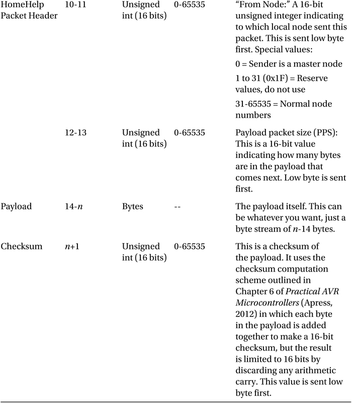
The HomeHelp protocol, version 1, packet layout is shown in the following table (all values in decimal unless otherwise noted):
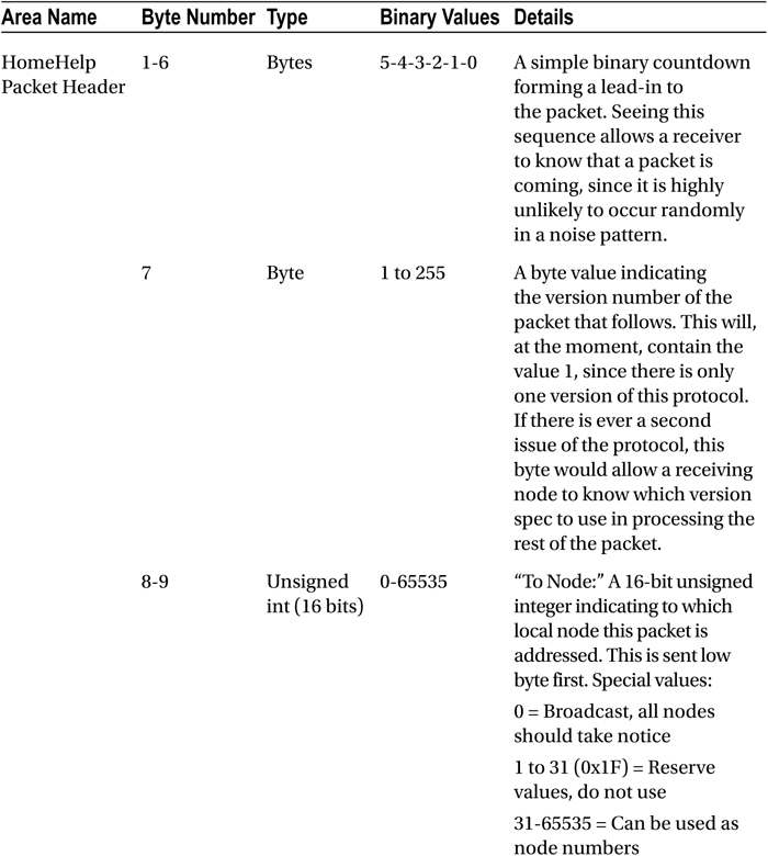
Obviously, in this scheme, you can put whatever you like in the payload section.
An important function of the software implementing the receiver end of this protocol is a timeout. If the channel starts delivering a packet but loses connection halfway through, it’s important that the receiving software knows when to give up and abort reception; otherwise it would be stuck waiting for the rest of the packet forever and the software would stall.
Using a Low-Cost Smart Home Wireless Node
In this project, you are going to build a simple door sensor. It will send a HomeHelp format wireless data packet whenever the door state changes. This will be sent to a simple receiving module, which will then display the status in a terminal window. Since the main point here is to show how to use the short-range wireless modules, the receiver is not going to be a hub node and the payload will be a single byte, not a fully qualified SHOM sequence.
In a real implementation, you would most likely want to use an 8-pin AVR (such as maybe an ATtiny85 chip) for the door sensor project, but you’ve been using the ATmega328 through this book, so let’s stick with that. You could, of course, rig up many sensors to this one controller, but you’ll use only one sensor in this example project.
Figure 6-6 shows a block diagram of the project. In summary,
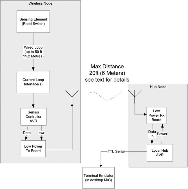
Figure 6-6. Wireless door opening monitor
- A door sensor is connected via a current loop isolator to a sensor controller AVR. The current loop interface allows you to have as long a cable run as you need to the door sensor; however, if you are able to locate the circuitry within a short distance from the sensor, you may be able to dispense with the current loop interface and just wire the sensor direct to an AVR input pin, thus saving the cost of the opto-coupler chip.
- The software constantly polls the state of the sensor. When a change of state is detected, it formulates an appropriate message and sends it out via the low power transmitter. Although the message is jacketed inside a HomeHelp format packet, the core of this message is very simple; it’s just a single byte that takes one of the following values:
- 01 = Started up (message sent after power on).
- 02 = Going away (sent if controller is commanded to power off or reboot).
- 03 = The door was closed and is now open.
- 04 = The door was open and is now closed.
- 05 = The door is open (sent periodically to confirm a door left open).
- The low power transmitter used in this circuit actually requires so little power that it can be powered from an AVR output pin! This allows the transmitter to be powered off by the MCU between transmissions. This reduced power supply requirement (if you used a low-power MCU such as an ATmega328-up) might make the project a candidate for battery operation, which for this kind of usage might be very handy!
- The message travels across the air to the receiver (RX) board. I have played around with several different products and ways of doing the antenna for them. I would say that, using just a wire antenna inside a home, you should regard 20 feet (about 6 meters) as the maximum distance over which you will get reasonably reliable transfer. Obviously, using more expensive sorts of antenna (and perhaps even with different makes of board) will get you different results.
- When the local hub AVR has received the message from the sensor node, it examines the contents. If the received message is valid, it decodes the meaning and puts out a message via its TTL serial channel to a terminal window running on a desktop machine.
Using just a piece of wire as the antenna, I have had communication between sender and receiver at a distance of about 40 indoor feet, but it’s very variable; some days it didn’t work at all. Over a distance of 20 feet, reliability is (with the setups I have tried) very good, and actually 20 feet is quite a long distance inside a home; in an average sized home it would get you from one room into the next. Usually, you would locate your hub receivers at strategic places out of sight. Such locations might include
- Up above the ceiling or in an attic space.
- In in-between floors space.
- In a crawl space.
- In a closet or under shelving.
- Under or behind a chair or couch.
- Hidden inside some piece of household equipment such as a clock.
As long as there is no radio block (such as a steel door or masonry containing lots of flint) between transmitter and receiver, you should not have a problem. You can get a lot more range albeit (at a cost that may work out to be several times more than the cost of the module!) by using a custom made antenna; however, I used a length of breadboard jumper wire, which did the job at almost zero cost.
I found that the length of the wire makes a big difference to the performance of the link. There seems to be an optimum length, so a little experimentation with different antenna wire lengths is worth the time it takes. I found that a wire between 7–9 inches (about 180mm–230mm) worked best, but I’m sure it’s highly product- and situation-specific.
The circuit diagram in Figure 6-7 shows the circuit diagram for the wireless sender. You could build this as a temporary breadboard project or as a separate small solder board inside a box if you want it as a permanent facility.
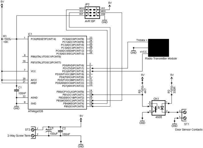
Figure 6-7. Door sensor wireless node circuit diagram
The MCU used is an ATmega328 (as noted earlier, you might want to use a smaller and cheaper AVR, such as an 8-pin ATmega85 in a real deployment). In this implementation,
- Pin 4 (Arduino digital in 2) is used to supply power to the radio transmitter module when needed (and only then).
- Pin 3 (Arduino TX) supplies the serial data stream to be sent over the radio transmitter module.
- Pin 15 (Arduino digital pin 9) is configured as an input to sense the state of the door switch. In the configuration shown, if the door switch is closed (i.e., the magnet is close to the sensor), then the pin will read as LOW.
- Other pins are used in the normal way for ISP programming.
The door sensor is interfaced to the MCU via an opto-coupler, which you are using as the current loop interface (see Chapter 4 of Practical AVR Microcontrollers [Apress, 2012], Figure 4-37, for more details). R3 is strictly redundant as you could use the internal pull-up resistor in the MCU, but you can use both if you so desire.
The power supply requirement for this project is +5Volts at a peak of 200ma; the average consumption on my prototype is only about 28ma.
The software for the door sensor project is pretty straightforward. Let’s do the code walk:
|
Function Name and Args |
Commentary |
|---|---|
|
Global section |
Declares all the constants, such as making the baud rate 2400, which pins to use, and the meanings of the single byte payload that the software will send. |
|
setup() args: none |
Initializes the serial channel and sets the required pin modes. Then uses sendPkt() sent out a packet with the “Started” value in it to let the receiver know it is alive. |
|
loop() args: none |
The loop function reads the door sensor state. If it’s active (door open), it uses sendPkt() to send a notification. Then it waits for the door sensor to return to the inactive state; when it does, it uses sendPkt() to send out a notification of that event. It would be nice to have the function send out a packet every now and again if the door remains open for too long, since under the right circumstances it might be useful for some function higher up the pecking order (such as a security application) to know that the door remains open. Recognizing that the door has been open for longer than it should be could also be implemented higher up the chain, but that would make it possible for false alarms to be generated if the doorOpen event packet made it through, but the subsequent doorClosed packet did not. The function also contains various delays to allow for switch debounce times. However, these are probably not required since the packet send delays probably amount to a long enough time between detecting the first switch closure and contact bouncing ending. Finally, the main loop pauses for half a second before starting again. |
|
sendPkt() args: byte payloadByte |
The sendPkt() function sends a HomeHelp format packet out with the door event code as the payload. The code to be sent is supplied by the function’s caller. Note that the sendPkt() function switches the radio transmitter on before it starts to send and off when it has completed. In both cases, it waits a short while to allow the transmitter to stabilize (at power up) and to complete sending (at power down). Since you’re only, in this instance, sending a single byte value over the link, the only byte that is used to calculate the checksum is that value! Therefore, the payload byte and the checksum are, in this unique case, always the same! |
The door sensor receiver is essentially (in the terms of the mixed network topology that was previously discussed) pretending to be a hub. All it really does is receive the packet from the door sensor sender, make sure the HomeHelp jacket looks okay, and call out the value of the payload as a string to a software serial port, as in these examples:
Received "Started up" from node 51
Received "Door was closed, is now open" from node 51
Received "Door was open, is now closed" from node 51
The receiver has to use a software serial port since the hardware port is used for the radio channel.
Door Sensor Summary
The door sensor sender is a simple project, mainly intended to show how to use low-cost radio modules to bring down the cost of your Smart Home installation. Using this approach allows you to install sensors and nodes wherever you like without having the mess and hassle of installing and trying to conceal long wiring runs.
The project is an example of a node that only outputs sensor data, but what about the reverse case? What about a node that only receives data?
Remotely Commandable Light Stand
The door sensor is an example of Smart Home device that only sends data into the Smart Home network. In this, the final example Smart Home project, you will look at a receive-only example.
This project is essentially a demonstration of using Smart Home techniques to command this class of device; only a very small part of its full potential is exploited here. I’m sure that readers will see endless additional possibilities!
We’re quite used to having remote control over things. We have remote control of our TVs, car alarm, DVD player, and so on. In this sample Smart Home project, you’re going to give yourself remote control of a special light project: a light stand or shelf!
It turns out that if you shine light through the edge of a thick piece of transparent acrylic plastic, most of the light will, if the edges have been smoothed and polished properly, travel through the material and come out of the edges opposite. This gives a really gorgeous effect, lighting up a shelf or a stand for something special. If the light used is a multi-color LED strip, then, by varying the intensity of each LED (using PWM) you can create light in any color you want, including white when all LEDs are at equal intensity. So, in this project, you can use the short-distance radio link (as detailed in the previous project) to remotely command the Smart Home node that controls the LED strip.
Let’s start with some basics: an RGB LED strip. Example products include
- www.sparkfun.com/products/10261 (United States and elsewhere)
- www.maplin.co.uk (UK; search for N48JX)
These are essentially flexible PCBs with tri-color, surface-mount LED devices fixed at regular intervals along their length. Each device actually contains three LEDS: red, green, and blue. The PCB provides a separate bus connection for the negative connections of all the reds, all the greens, and all the blue connections; there is also a +V lead that connects to all LED devices. The examples listed above use +12Volts, but I believe there may also be +5V products around if you look for them.
The strips have “cut points” marked along their length (see Figure 6-8), which present solder pads for attaching your connections (as shown in Figure 6-9).
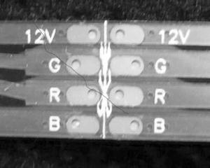
Figure 6-8. LED strip showing cut point
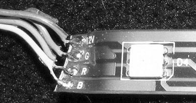
Figure 6-9. LED strip cut and wires soldered on
Your first decision is to decide how many lengths you want to use. I used three, which, since there are three LEDs per length, gave me nine tri-color LEDs in my setup. You could use more or less; the current consumption of the LEDs in these types of product is not huge (check your product details for specifics) so using more is fine. Having decided how many LED lengths you want to use, you should now be able to decide the sizing for your slab of plastic!
I bought my plastic shelf from an EBay vendor (there are many) who also offers a cutting and polishing service. It is made of 10mm (about 0.4”) thick transparent plastic. I chose this thickness to match the width of the LED strip to make it easy to mount the LED strip along the edge of the stand. I want to use it as a stand for a miniature MP3 jukebox; you’ll see how this goes together a little later. I had the vendor cut the shape I wanted and polish all the edges. This was not especially cheap (about $35) but the result was excellent, as you can see in Figure 6-10.

Figure 6-10. Light stand
Next, I got a plastic angle from the home improvement store (with an L-shape profile), cut it to length, and used some standard general purpose adhesive to fix it onto the plastic stand, such that it provides a channel to drop the LED strip into. The photo in Figure 6-11 shows this detail.

Figure 6-11. LED strip channel
Then, I soldered my four wires, making them about 3 feet long (2.7m) to the LED strip. Most of these LED strips come with a sticky back that allows you to stick the strip onto something. Thinking ahead, though, I imagined how hard it would be to remove this if the LED strip ever failed or if I wanted to swap it out for a different type. So, instead of using the sticky back, I put some 1” black insulating tape along the underside of the LED channel to hold the strip in place in its channel. And that was it; the light stand ready to go, as shown in Figure 6-12.
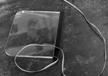
Figure 6-12. Light stand with LED strip in place and cable attached
The electronics are pretty simple. It’s another two-chip project with just the ATmega328 AVR chip and a 2803 driver. However, it does requires the split rail power supply, capable of giving +12Volts for the LEDs and +5Volts for the AVR.
On the LED string product I was using, each colored LED (e.g., the red LED inside just one of the surface mounted devices) consumed a maximum of 7 milliamps. As mentioned previously, I used nine RGB devices along my LED strip. So the current requirements, in my case, were
- 9 x 7 milliamps for the red LEDs = 63 milliamps
- 9 x 7 milliamps for the green LEDs = 63 milliamps
- 9 x 7 milliamps for the blue LEDs = 63 milliamps
Thus the current requirement for the +12volt supply was, in my case, less than 200 milliamps, and the amount of current to sink for each set of colored LEDs was very easily within the capability of a 2803 chip. The full circuit diagram for the project is shown in Figure 6-13.
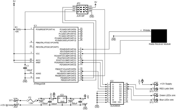
Figure 6-13. Light stand project circuit diagram
As you can see from the diagram, there’s not an awful lot to it. The radio receiver module connects to the AVR’s serial receive line. Pins 11, 12, and 15 (Arduino digital pins 5, 6, and 9, respectively) connect to the 2803A driver chip in which the first three drivers are used to sink current from the red, green, and blue LED elements, respectively. The remaining drivers in the chip are unused and their inputs grounded. The AVR’s pin 4 (Arduino digital pin 2) is used to supply the minimal amount of power required by the receiver module. This allows the AVR to disable the receiver if necessary.
The RGB LED strip connects via a set of screw connectors; in a permanent version of this project you could use a small 4-way connector (see the Waterfall Lights project sensor connector for a suitable example).
Light Stand: RGB Values Sender
The software and hardware for the light stand is almost exactly the same as what you used for the door sensor. There are just three differences:
- In the hardware for this project, there is no door sensor interface.
- In the software,
- Rather than having to wait for the door sensor to go active, the loop() function just sends a HomeHelp format packet containing a 4-byte payload consisting of a command code (which is always zero) and three randomly chosen RGB values. Such a packet is sent about every 10 seconds.
- The checksum value is no longer a repeat of the payload; it is now properly calculated, based on the values sent in the payload.
The sender circuit diagram is shown in Figure 6-14.
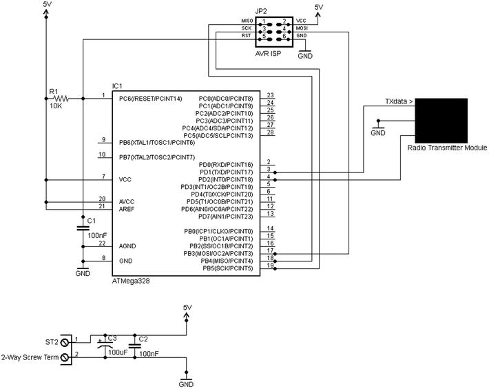
Figure 6-14. Radio sender for the light stand project
Aside from these differences, the hardware and software for the light stand sender are the same as those used for the door sensor sender. The payload sending order is shown in the following table:
|
Payload Byte # |
Byte Usage |
|---|---|
|
1 |
Command code. Currently, the only command that the receiver recognizes is zero, meaning that the remaining three bytes contain RGB values. Many more ideas are possible (see below). |
|
2 |
Red value (8-bit byte): This is a PWM intensity value for the red LEDs. |
|
3 |
Green value (8-bit byte): This is a PWM intensity value for the green LEDs. |
|
4 |
Blue value (8-bit byte): This is a PWM intensity value for the blue LEDs. |
Clearly, you could do a lot more with this. For example, you could implement anything up to 254 additional command codes for the receiver to action. Such commands might be
- Do fade up or down at some specified speed.
- Do random colors locally.
- Flash the LEDs at various speeds.
- Do a local sequence to gradually step through all possible colors over a period of n minutes.
- Do color chaser.
- Set LEDs to one of n preset colors (stored in the MCU’s EEPROM).
- Do a light show.
All kinds of possibilities exist, and as always with MCUs, they are yours just for the working out!
Light Stand Software: Receiver
The software for the light stand is quite long, but in fact only consists of three functions! Let’s do the code walk:
|
setup() |
The usual setup function contents; it declares the pin numbers being used as PWM to sink the LED lines for red, green, and blue. Also declares the memory construct that holds the current values for RGB. Initializes the serial channel via which the software listens for commands coming in via the low cost short range radio. It initializes the PWM values so that the LEDs are all off. Then it declares the radio receiver pin and applies power to the receiver board. |
|
loop() |
Probably the simplest loop() function yet! It calls the getPacket() function. If the function returns a correctly received packet, the values it contained are written out to the LED PWM control pins to set the required red, green, and blue levels. |
|
getPacket() args: timeoutMS |
This function is the big one here. It receives and verifies a packet from the radio network in the format described in the “A Simple HomeHelp Protocol” section earlier in this chapter. It waits for a packet to turn up, but only for timeoutMS. If a packet is received (or begins to be received) during that window, it receives it, verifies the checksum, and if all is well, it returns success and passes back the payload in the global text buffer. If no packet is received before the timeout is reached or the packet is received in error, it returns a failure and the buffer contents will be invalid. |
The code for this project is a good illustration of one of the principal things MCU chips have changed. The processor in this project will spend most of the time just whizzing around the loop() and getPacket() functions waiting for something to do! Even 20 years ago, this would be almost a crime because CPUs were a comparatively expensive resource that you had to make best possible productive use of. Back then, if you were making a project like this, you’d probably look for other things the unit could do so as not to waste any processing time.
However, MCUs (and indeed microprocessors) changed things by making processing power very, very cheap by comparison to what it had been; so now it’s okay to only use a small part the available processing power productively.4 You can have a separate processor for each little function within a system, almost the mirror image to the old-time home automation idea that you started off this chapter with (i.e., the monster computer in the basement)!
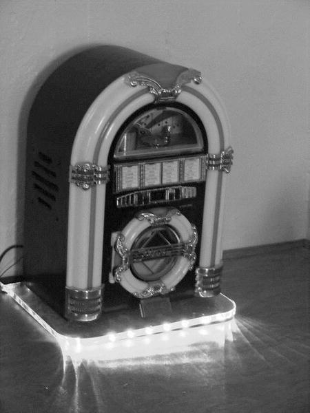
The Light Stand in Action
The photo sequence of Figure 6-15 through Figure 6-17 gives an idea of the finished result.
|
In this photo, the stand is illuminated in response to a radio command. The table-top jukebox lighting is off. |
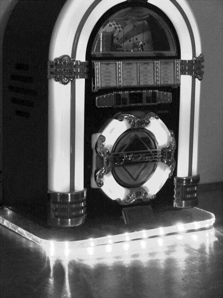
|
In this photo, the MP3 jukebox lights are also on, completing the effect. |
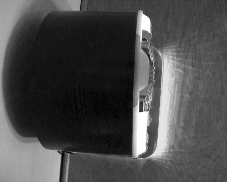
|
In the final view (from above), you can see the light prongs radiating out. In a darkened room, these reach out quite a long way. |
Summary
In this chapter, you have taken a necessarily brief look at the concept of the Smart Home and some of the history behind it. You’ve looked at some ideas that, for the technically-able Smart Home maker at least, can break the communications log-jam that I personally believe holds back the Smart Home from going truly mainstream.
You’ve looked at how to use a mixture of low-cost, easily available technologies to join up the islands of intelligence within a Smart Home infrastructure. Of course, all you have seen here is a set of individual ideas and small projects, not a detailed implementation. Nevertheless, I hope that this brief foray into this area has provided you with enough inspiration to get going on some of your own ideas!
__________________
1If your interest is more in the area of hacking TV-style IR remotes, have a look at Ken Shiriff’s excellent Arduino IR Library at www.arcfn.com/2009/08/multi-protocol-infrared-remote-library.html.
2Please remember that SHOM is not any kind of standard; it’s just something I invented to show how a slim protocol can be developed for use within a closed environment.
3In passing, it’s worth noting that even unencrypted traffic on a wired LAN can be listened to outside of your home by someone with sufficiently sensitive equipment—though such equipment is said to be very expensive.
4Many might argue that it’s bad computer science but at least now it’s not compounded by being financial folly, too!