Now that you have some VFX and new media content production software installed, covering areas like digital illustration, digital audio editing, digital imaging, digital video editing, and visual effects (VFX), it is time to get into all of the underlying concepts, like raster, motion, vector, and audio, that span these multimedia genres and come together as one inside of your VFX software package—in our case, Fusion 8.0. The concepts covered over the next few chapters will provide an overview of what is contained within your visual effects assets, projects, and effects-processing pipeline. We will cover motion concepts in Chapter 3 and audio concepts in Chapter 4.
Digital imaging software, such as GIMP and Photoshop, and digital video software, such as Lightworks, use raster, or pixel-based, technology. My book Digital Image CompositingFundamentals (Apress, 2015) is useful if you want to delve deeper into raster imaging. There is also the vector, or math-based, technology that is used for illustration and 3D software packages, like Inkscape, CorelDraw, and Blender. We’ll be covering vector in the next chapter, as it’s different from raster imaging, although vector assets can be rasterized.
I will start with low-level concepts during these first few chapters. In this chapter we will discuss raster images and foundational concepts behind raster imagery. I will cover pixels, resolution, aspect ratio, color space, color depth, masks, alpha channels, anti-aliasing, layers, blending modes, palettes, and dithering. We need to get all of this technology lingo out of the way during the first few chapters so that you will understand the concepts that are found in the remaining chapters. Bear with me if you already understand the fundamental terminology that is used for VFX and new media content production pipelines and workflows. I will try to cover all these topics in as few pages as possible!
Raster Image Concepts: Arrays of Pixels
The raster approach to digital imaging is completely different from the vector approach. Whereas a vector approach uses math to define imagery using illustrations, which are created by SVG commands, or 3D geometry, using polygons and splines, the raster approach uses tiny dots called pixels to create the image. You have to look at these pixels all at once—not close up, but from a distance. Imagine those LED (Light Emitting Diodes) signs in Las Vegas, where you can’t see what is on a sign when you are right in front of it, but can see a brilliant image once you’re the right distance away.
Picture Elements: Pixels Are the Raster Image Building Blocks
Digital imagery is made up of two-dimensional “arrays” or grids, which contain pixels. The industry term pixel is the combination of two terms: pictures (hip folks call these “pix”) and elements (shortened to be just “els”). Thus, the foundation for any digital image that you will be working with are its picture elements. These pixels dictate everything about your digital image asset, like its file size, dimension, color, transparency, and shape. It is important to note that vector or digital illustration assets are not made up of pixels, at least not until the SVG command that composes the vector is converted to pixels using an algorithmic process called rasterization. The digital image asset used in digital video pipelines can be said to be “static” (that is, without motion), whereas digital video will be said to be “dynamic,” because it does incorporate motion. We’ll be covering what makes digital video dynamic in the next chapter when we cover frames and 4D (animation) concepts.
Image Resolution: The Number of Pixels in Your Raster Image
The number of pixels contained in your digital image asset will be expressed using a term called resolution. This term also applies to digital video assets, as each frame contains the same number of pixels along the X and Y dimensions. Resolution contains a width, which is usually denoted using a W, or alternatively using an X, which stands for your x-axis, as well as a height, which is denoted using an H or a Y, which stands for the y-axis. The image (or video) resolution gives you the digital image or video dimensions. For instance, the popular VGA resolution would be expressed by specifying 640 x 480. Alternately, you could also use the word “by,” like this: 640 by 480. XGA resolution is 1024 by 768, Blu-ray resolution is 1280 by 720 pixels, HDTV resolution is 1920 by 1080 pixels, and Ultra HD resolution is 4096 by 2160 pixels.
To find the total number of pixels that are contained in any 2D digital image, you will want to multiply width pixels by height pixels, or, in coding terms: Resolution = Width * Height.
To find the total number of pixels that are contained in any 2D digital video, you will want to multiply width pixels by height pixels, by the number of video frames, or, in coding terms: Total Pixels in Digital Video = (Width * Height) * TotalFrames.
Hopefully, you remember the area of a rectangle equation from grade school. Here it is again in a professional digital video editing project context. For example, an HDTV image with a resolution of 1920 x 1080 pixels will contain 2,073,600 pixels, which you can determine if you multiply the width and height together. If you like digital photography, you’re probably familiar with the term two megapixels, which refers to 2 million pixels. This is essentially what this HDTV resolution is giving you in terms of the number of pixels.
The more pixels that are contained in the digital image or digital video, the higher its resolution will be said to be. Higher resolution imagery and video will give your viewers more detail, or image subject matter definition. This is why 2K HDTV is called high definition, and why the new 4K resolution UHD TV is called ultra-high definition(4096 pixels is called “4K”).
Image Aspect Ratio: A Ratio of W:H Pixels in an Image or Video
Closely related to the resolution of the digital image or video is the ratio of X to Y pixels in a digital image. This is called the aspect ratio. This concept is more complicated than that of resolution, because it is the ratio of width to height, represented as W:H, that exists in an image or video resolution (dimensions). If you like to think in terms of an image x-axis and y-axis, this would be X:Y. This aspect ratio defines the shape for your image or video, and the concept also applies to the shape of a device’s display screen. For instance, smartwatches will have a square aspect ratio of 1:1, and your ultra-wide iTV set will feature a rectangular 2:1 aspect ratio.
A digital image (or display screen) with a 1:1 aspect ratio can be said to be perfectly square. Since this is the aspect ratio, a 1:1 aspect ratio is the same as a 2:2 or a 3:3 aspect ratio. It is important to note that it is this ratio between the two numbers X and Y that defines the shape of the image or video, not the numbers themselves, and that is why it is called an aspect ratio—although it’s often called aspect for short. A 2:1 aspect ratio would create a widescreen image. A 3:1 aspect ratio is usually called a panoramicaspect ratio.
Your image aspect ratio is generally expressed using the smallest set or pair of numbers that can be achieved (reduced to) on either side of the aspect ratio colon.
If you paid attention in high school when you were learning about the lowest (or least) common denominator, these aspect ratio calculations should be fairly easy for you to comprehend.
I would do this mathematical problem by continuing to divide each side by two. Let’s take a fairly weird 1280 x 1024 (this is the “SXGA” or “Super XGA”) resolution for our example.
Half of 1280:1024 is 640:512, and half of 640:512 would then be 320:256. Half of that is 160:128, and half of that is 80:64. Half of that is 40:32, and half of that is 20:16. Half of that is 10:8, and half of that is 5:4. Therefore, an SXGA resolution uses a 5:4 aspect ratio, which is fairly close to being square. The larger and closer your numbers on the two sides of the colon are to each other, the squarer the rectangle defined by the aspect ratio is. Thus, a 5:4 aspect is squarer than a 4:3 aspect, which is squarer than a 3:2 aspect, which is squarer than 2:1 aspect.
Interestingly, all the SXGA ratios in that example were the same aspect ratio and were valid. Thus, if you wanted to take the really easy way out, replace that “x” in the image resolution with a colon, and you have an aspect ratio for that image. The industry standard involves distilling an aspect ratio down to its lowest format, as we’ve done here, as that is the most useful ratio. Next, let’s look at how pixels define colors!
Digital Color Theory: Each Pixel Contains 3 RGB Color Channels
Within the array of pixels that makes up your resolution and its aspect ratio, each pixel will hold color values, using three color channels, in something called the RGBcolor space. RGB stands for the red, green, and blue color values each pixel can define to establish what color that pixel is. Since devices that are going to display your image or video assets use this RGB color space to do so, we will use this RGB color space throughout this book, rather than other color spaces, such as YUVor YCbCr, which are more frequently used with analog (broadcast, reduced color spectrum, or interlaced) video. The digital, 24-bit, non-interlaced color devices made these days do not require YUV color data, which is used to correct for, or optimize for, human perception of color.
There are advanced techniques that can be implemented by switching between different color representations, such as YCbCr and YUV to RGB and HLS (hue, luminance, saturation), but these are beyond the beginner scope of this VXF Fundamentals title.
Color channels were originally used in digital image compositing programs like GIMP for compositing digital imagery for use on display screens. The digital video editing software I’ll be using provides a nearly identical compositing pipeline, as will the Fusion 8 visual effects software package.
Color channels are sometimes referred to as color platesin the printing industry due to older printing presses, which use metal plates. Some of these presses are still in use today.
In GIMP, color channels have their own Channels palette that allows us to work on just that color channel (or plate), which can be quite useful for special effects or other advanced image operations. Editshare Lightworks also has a Channels feature. There is a Red (light) channel with 256 levels of light or brightness, a Green (light) channel with 256 levels of light or brightness, and a Blue (light) channel with 256 levels of light or brightness under the Channels tab.
An opposite of RGB, or additive, color is subtractivecolor (CMYK), which is used in printing and involves using inks. Inks subtract color from each other, rather than adding color, which is what happens when you combine different colors using light.
Taking red and green as an example, using additive color, Red + Green = Yellow. Using subtractive color, Red + Green = Purple. As you can see, additive gives you brighter colors (adds light) while subtractive gives you darker colors (subtracts light).
To create millions of different color values using these RGB color channels, what you will need to do is vary the levelsor intensitiesfor each of the individual RGB color values. The number of red, green, and blue values, or levels of intensity of light, that you have available to mix together will determine the total number of colors that you will be able to reproduce. A color needs to be generated for every image pixel.
Every pixel in an image will contain 256 levels of color intensity for each of the RGB (red, green, and blue) color data values. Color intensity (or brightness) data inside each of the digital image pixels is represented with a brightness level for each color. This can range between zero (brightness turned off, or black) and 255 (brightness fully on; fully saturated color). This controls the amount of color contributed by each pixel for each of these red, green, and blue colors. As far as digital video goes, each frame is a digital image, in essence, so everything that applies to digital imaging applies to digital video too.
Calculating a total amount of available colors is easy, as it is again simple multiplication. If you multiply 256 times 256 times 256 you get 16,777,216 colors. This represents the number of unique color combinations of red, green, and blue that you can obtain using these 256 levels (data values) per color that you have to work with across these three different additive color channels. If you are using 16-bit color you have 65,536 colors, and 8-bit color offers 256 colors. The multiplication involved is simple.
There are also new 48-bit color and 64-bit color models, which are used in VFX production pipelines where HDRI, or High Dynamic Range Imaging, is utilized. This is usually done with a 3D content production workflow, or with expensive film or 4K DV cameras, which have support for 16-bit color (so, 65,536 colors) per color channel, allowing for a much higher dynamic color range (65536x65536x65536).
Image Color Depth: Bit Levels Will Define Your Number of Colors
The amount of color available to each pixel in a digital image is referred to in the industry as the color depth. Common color depths used in digital images and video include 8-bit, 16-bit, 24-bit, 32-bit, 48-bit, and 64-bit.
The true colordepth image will feature the 24-bit color depth and will thus contain 16,777,216 colors. High colordepth images feature 16-bit color depth (256 x 256 = 65,536 colors) in an RGB565 (five bits red, six bits green, five bits blue) data configuration.
Image file formats that support 16-bit and 24-bit color depth include the BMP, XCF, PSD, TGA, and TIFF. True color–only image formats include JPEG (JPG), PNG24, or WebP (WebPhoto). For digital video, MPEG-4 H.264 and H.265 and WebM support 24-bits.
Using true color depth will give you the highest quality level. This is why I’m recommending the use of PNG24 or PNG32 imported image assets for visual effect compositing pipelines, or for your digital video editing compositing, or for a digital image editing and compositing workflow.
Figure 2-1 shows a true color image created with Autodesk 3D Studio Max, which uses 24-bit color space. Notice the higher quality of the image when compared to Figure 2-2, which uses a lower 5-bit color image quality that uses 32 colors instead of 16,777,216 colors to create the image.
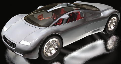
Figure 2-1. High-quality 24-bit true color digital image example

Figure 2-2. Photoshop Save for Web dialog showing indexed color
Next, let’s take a look at indexed color in case you need to use PNG8 or GIF assets in your visual effects pipeline, or in case you have to use existing digital image assets that do not have the advantage of 24-bits, 32-bits, 48-bits, or 64-bits of color.
Indexed Color Depth: Using Palettes to Hold 256 Colors
The lowest color depth exists in 8-bit indexed colorimages. These feature a maximum of 256 color values (2 to the 8th power, or 8 bits of Binary data, known as a “byte”) and use an indexed “palette” of colors, which is why they are called indexed color images. Popular image file formats for indexed color include GIF, PNG8, TIF, BMP, or Targa. The indexed color palette is created by the indexed color codec when you export your file from an imaging software package, such as GIMP. Codec stands for COde-DECode and is an algorithmthat can optimize a file size to be smaller using compression.
The way you convert 24-bit, true color image data to this indexed color image format (GIF or PNG8) in Photoshop is to use the File ➤ Save for Web menu sequence. This will open your Save for Web dialog, which will allow you to set a file format (GIF or PNG), number of colors (from 2 up to 256), color conversion algorithm (perceptual, selective, adaptive, or restrictive), the dithering algorithm (diffusion, pattern, or noise), and a number of other advanced options, such as progressive interlacing. The dithering algorithminterleaves pixels of neighboring colors in an attempt to create the illusion of a smooth color transition.
To convert true color image data into indexed color image data using GIMP 2.8.18, you would use the Image ➤ Mode ➤ Indexed menu sequence. This will call up an Indexed Color Conversiondialog. This has fewer options than your Photoshop Save for Web dialog, but the important ones are there so you can specify color depth and diffusion dithering. I recommend using the GIMP Floyd-Steinberg diffusion dithering algorithm . There is even an algorithm that reduces color bleeding, thus keeping imagery edges clean and sharp.
As an example of color depth, if you selected two colors, that would be a 1-bit (PNG1) image, four colors would be a PNG2 (2-bit color depth) image, sixteen colors would be a 4-bit PNG4 color depth image, sixty-four colors would be a 6-bit PNG6, and one hundred twenty-eight colors would be a 7-bit PNG7 image. In case you’re wondering, there are digital video formats that can support indexed color digital video, like the aGIF, or animGIF, format does, but with synchronized audio. I am a data footprint optimization aficionado, thus I’d suggest that the more mainstream video codecs add an 8-bit color optimization algorithm to allow video editors to have the capability to optimize faster, smoother video.
Next, let’s take a look at the other color format, 24-bit true color, or 32-bit true color plus alpha channel transparency.
True Color Depth: Using 24-bit True Color Imagery
One of the most widely used digital image file formats in the world is the JPEG file format , and it only comes in one flavor: 24-bit color. Other file formats that support 24-bits of color data include Windows BMP, TIFF, Targa (TGA), Photoshop (PSD), and PNG24. Since the PNG format supports 8-bit (PNG8) or 32-bit (PNG32) color, I call a 24-bit PNG format PNG24 to be precise. The primary difference in the true color file formats comes down to a format characteristic: lossy versus lossless compression .
Lossy compression means that an algorithm, which is also called a codec (COde-DECode), throws away some of the data to achieve a smaller data footprint. For this reason, save your original, uncompressed file using a lossless format prior to applying any lossy compression—in this case, JPEG. It is important to note that MPEG-4 and WebM are lossy video formats.
Lossless compression, used by the PNG, GIF, BMP, TIFF and TGA formats, doesn’t throw away any original image data; rather, it applies an algorithm that finds patternsthat result in less data being used, and that can 100 percent reconstruct all of the original pixel values.
True color images are used for user interface design or for websites and application content. They can also be used for other digital content, such as that used for e-Readers, iTV set apps, games, smartwatches, e-Signage, and social media sharing forums that support digital imagery, videos, or illustration. We will be using true color images for visual effects pipelines, as we need a high-quality color space to be able to pull off an effects-processing result that’s visually realistic in the end.
Using more than one image or video is called layer compositing. Compositing involves using more than one asset, arranged in several layers. Your background, or backplate, video uses 24-bit image data. All the other layers in a compositing stackabove a background plate need to support transparency, and will need to use 32-bit, known as ARGB or RGBA, image or video data.
This transparency is provided by a fourth channel, known as the alpha channel. I’m going to introduce you to this next.
True Color Plus Alpha: Using 32-bit Digital Imagery
Besides 8-bit, 16-bit, and 24-bit digital imagery, there is also 32-bit digital imagery . Formats that support the 32-bit color depth include PNG, TIFF, TGA, BMP, and PSD. I like to use PNG32, as it’s supported in HTML, Java, JavaFX, CSS, and Android, while other file formats are not used in open source platforms.
These 32-bits of image data include 24-bits of RGB color data, plus 8-bits of “alpha,” or transparency, value data, held in what is commonly referred to as your alpha channel.
Since you now know that 8-bits holds 256 color values, it will make sense to you that an alpha channel will hold 256 different levels of transparency data values for each pixel in a digital image. This is important for digital video compositing, because it allows layers that hold this 32-bit image data to allow some portion (from zero to 255, or all of that pixel’s color) of the color data to bleed through to (or to blend with) layers below.
Next, let’s take a closer look at what alpha channels do.
Alpha Channels: Defining a Transparency Level for Each Pixel
Let’s take a look at how alpha channels define digital image as well as digital video pixel transparency values, and how they can be utilized to composite digital video compositions. Alpha channel data provides transparency inside of the visual effects compositing pipeline in software such as Fusion, Lightworks, GIMP, Blender, and Inkscape. Alpha data can be used in both static (imaging) or dynamic (VFX, video) compositing pipelines to composite digital images and video together in real-time using Fusion VFX software, as well as open platforms such as Android Studio, HTML5, CSS3, Java, JavaFX, and PDF. I would term code compositing using these platforms as “interactive dynamic” use, as the code allows you to access the pixel transparency values interactively in mere nanoseconds of time. This allows you to animate the data in any way that you like, as well as make it respond in real-time to the user’s control. This can be used in websites, games, animated user interface designs, iTV programs, interactive e-Books, digital signage, and smartwatch faces.
Visual effects compositing involves the seamless blending of more than one layer of digital image, digital video, and digital illustration assets. As you might imagine, per-pixel transparency, provided by each asset’s alpha channel, is indeed an important concept when you have more than one layer involved in a digital video editing or visual special effects project.
Visual effects compositing needs to be used when you want to create a video on a display that appears as though it is one single video, but that is actually a seamless collection of more than one composited image and video content layers.
One of the principle reasons you would want to set up an image, video, audio, and animation composite is to allow you to exercise fine-tuned control over various elements by having different new media assets (components) on different layers. In digital audio, which we are going to cover in Chapter 4, these layers are termed “tracks.” To accomplish a multi-layered composite—with the exception of digital audio, where silence would be the equivalent of transparency—you will always need to have pixels with alpha channel transparency data values located on layers that are above your backplate (or background).
Alpha channels can be utilized to precisely control the opacity blendingof each pixel’s color with the pixels in the same X,Y location on the layers below it.
Like the RGB color channels, the alpha channel will have 256 levels of transparency, from 100 percent transparent (zero) to 100 percent opaque (255). Each pixel will have different alpha transparency data, just like each pixel will have different RGB color values.
This is the reason that the Layers and Channels tabs for software packages such as GIMP, Photoshop, Painter, Lightworks, Pinnacle Studio, Inkscape and VideoStudio Ultimate are grouped together using a floating palette. You will observe this user interface design commonality as you use the different new media software packages over the course of this book .
Porter-Duff: Algorithmic Pixel-Blending Modes for Each Layer
There is another powerful aspect of layered compositing called blending modes. Any of you who are Photoshop or GIMP users have seen that each layer is able to be configured to utilize a different blending mode. Blending modes are algorithms. These specify how the pixels for each composited layer are blended mathematically with the compositing layers underneath that layer.
These pixel-blending algorithms take into account a pixel’s transparency level. Between these two image compositing controls, you can achieve virtually any compositing result that you are trying to achieve using GIMP, Photoshop, Painter 2016, Inkscape, Lightworks, Blender or Fusion 8.
A major difference on dynamic platforms such as Android is that blending modes can be controlled interactively using custom Java or JavaFX programming logic. Some of these powerful PorterDuff J ava class blending modes include XOR, ADD, SCREEN, OVERLAY, DARKEN, LIGHTEN, and MULTIPLY. The Pro Android Graphics (Apress 2013) title covers how to implement PorterDuff blending modes inside the complex image compositing pipeline, if you are interested in learning about Android Studio programming or Java-based layer compositing. Next, let’s learn about anti-aliasing.
Smoothing the Edges in Digital Image Composites: Anti-Aliasing
Anti-Aliasingis a popular digital image technique that is also implemented using an algorithm. This algorithm finds where two adjacent colors meet along an edge and blends the pixel colors together along that jagged edge. Anti-aliasing will add averaged colorsalong the edge between two colored areas to visually smooth those two colors together along the (formerly) jagged edges. This will make jagged edges appear to be smoother, especially when your image or video is zoomed out, such that the individual pixels are not easily discernable.
Anti-aliasing tricks the eyes into seeing smoother edges, eliminating what’s commonly termed the jaggies. Anti-aliasing provides impressive results using a few (usually fewer than eight) intermediary averaged color values for those pixels that lie along the edges within an image or video layer that contains assets that need to be made to look smoother.
By averaged color I mean a color or a spectrum of colors whose shade is part of the way between the shades of the two colors that intersect along that edge being anti-aliased. I created a visual example of anti-aliasing for you to show the resulting effect. I first created the seemingly smooth red circle, seen in Figure 2-3, against a yellow background. I zoomed into an edge of that circle, and then I grabbed a screenshot. I placed this next to the zoomed-out circle to show the orange anti-aliasing pixels. Notice there are seven or eight averaged colors that are used to create this visual effect, which is really not that many, if you think about it. As you see on the left, the result is a sharper edge.

Figure 2-3. The zoomed-in right view shows anti-aliasing effect
One of the nifty tricks I utilize to implement my very own anti-aliasing effect is to use a Gaussian Blurfilter on any jagged edges in digital compositing layers in Photoshop, VideoStudio Ultimate, GIMP, Pinnacle Studio, Painter, Fusion 8, Lightworks, and Lightworks Pro (the paid version of Lightworks).
Be sure to use low blur values (0.15 to 0.35) on subject matter (as well as on alpha channels, if you are anti-aliasing the transparency mask) that contains these jagged edges.
This will provide the same anti-aliasing effect that you see in Figure 2-3, and not only that, it will “blur” the alpha channel transparency values as well so you are smoothing the composite between any two layers in real-time. This is significantly more advanced. I’ll try to cover advanced techniques whenever possible, even though this is a VFX fundamentals book and not an intermediate or advanced visual effects title.
Blurring the alpha channel will allow it to anti-alias a 32-bit image object with any background imagery you may be attempting to seamlessly composite it against, which I call real-time anti-aliasing. It is implemented using “static” alpha channel data contained within what is essentially a black and white image used as a transparency blendingguide. The grey pixels on the edge in the alpha channel data will then tell the compositing pipeline to average the colors between the current layer and those pixels (colors) that are underneath it in your digital effects or digital image compositing project.
Summary
In this second chapter I made sure you had a solid foundational understanding of raster image concepts, since these concepts will be needed in VFX, digital video, and 3D software when 2D “static” new media components are imported for use in the digital image asset layer compositing pipeline for your digital VFX projects. We looked at the raster image concepts and terminology especially carefully, as raster image assets are used in just about every stage of the VFX content creation pipeline. We learned about pixels, resolution, and aspect ratio, and how to calculate each of these mathematically. Then we took a look at color modes, color channels, and color depth, and how they define color within your digital visual effects projects.
Next, we looked at more advanced concepts such as layer compositing, alpha channels, pixel-blending modes, PorterDuff algorithms, and anti-aliasing algorithms, all of which we will be using during this book so that you get hands-on experience in order to become a visual effects pro.
In the next chapter you’ll take a look at frames and how these turn digital imagery into dynamic motion digital video.