Now that you have an understanding of some of the advanced 2D features in Fusion 8, let’s spend the rest of the book using Fusion in its entirety, which includes using the 3D compositorand its features. In this chapter, we will look at how Fusion differentiates 2D and 3D, how it bridges them together seamlessly, and how to add new 3D elements into your VFX project pipeline. With this knowledge we will be able to incorporate 3D elements and assets for the rest of the book (the advanced topics chapters).
Advanced Compositing: Fuse 2D with 3D
Fusion continues to add new features that make it worthy of its powerful name, fusing traditional 2D image-based compositing and 2D mask vectors with rapidly emerging 3D vector geometry-based modeling and animation. As you know from the first section of this book, 2D image layers only have infinitely flat X and Y dimensions, which does not match up with the reality of film, TV, or 3D game production, where content is either captured with a live-action camera in a 3D environment or has been created in 3D modeling, surfacing, animation, effects, and rendering applications.
Fusion 6 added an OpenGL GPU hardware–accelerated, 3D compositing environment to the flow node editor, adding support for geometry , point clouds , and particle systems. This opened up the software to new features such as taking 2D images into 3D space and importing cameras , lights , and textures from 3D applications such as Autodesk 3D Studio Max by using the FBX file format.
Fusion continues to add i3D features, enabling realistic surfaces by using illumination algorithms and shader compositor tools and workflows. You can render 3D using realistic depth-of-field settings, and you can use motion blur and super sampling . You can extrude 2D text into 3D text and bevel it, and you can cast shadows across 3D geometry using VFX pipeline elements.
Fusion 3D Scenes: 3D Tools for 3D Environments
Fusion has 3D tools that allow you to add 3D compositing, enabling you to create an environment supporting your 3D assets while also maintaining your 2D compositing pipeline containing digital imagery, digital video, digital illustration, or digital painting assets. In Fusion, if you want to “fuse” 3D with your previously 2D VFX compositing pipeline, you would use the Add Tool ➤ 3D menu and its related Material, Texture, and Light sub-menu structures, shown in Figure 14-1. Also shown are the FBX mesh 3D node tool and a Gargoyle.FBX file imported from Autodesk 3D Studio Max, just to show you what is possible.

Figure 14-1. Fusion adds 3D compositing features via the 3D menu and its sub-menus
These 3D tools will allow you to do things like create “ primitive” geometry, such as a flat plane , cube , sphere , torus , cylinder , or cone , or import complex geometry (mesh ) objects, as I did to create Figure 14-1. You can create lights and cameras, point clouds, projectors , text, and fog, and warp, deform , bend , duplicate, displace , weld , transform , and UVW map 3D geometry.
When you create a Fusion composition, you do not need to define whether it will be 2D or 3D, because you will use nodes or tools to seamlessly combine your 2D and 3D scenes. As you will see in the final two chapters, particle systems do need to be defined as 2D or 3D, however.
As you will see in Chapter 15, 3D geometry will be added to your VFX pipeline using primitives (3D shapes), image planes, and FBX mesh 3D assets imported using an FBX mesh 3D node tool.
3D geometry is combined with lights and cameras by using the merge 3D tool, and is rendered to 2D images using the renderer 3D tool.
As you will see in Chapter 15, the surface appearance of your geometry can be defined using material tools, such as your Blinn and Phong tools. Materials can use textures that apply 2D images or 3D environment maps using UVW mapping coordinates .
Whenever these tool nodes have their viewports selected, a 3D viewer will replace the 2D viewer we have been using thus far in the book. This allows you to navigate and manipulate your VFX pipeline using 3D. The interactive 3D viewer is highly dependent on the computer graphics hardware, relying on support for OpenGL, which is why we got into GPU hardware in Chapter 1. The amount of DDR5 memory, as well as the number of processors, processor speed, cache, and features of the graphics processing unit (GPU) will define the smoothness of operation and quality of the rendered visuals that will appear in your i3D viewer .
Bridge 3D and 2D VFX Projects: Merge and Render
As you probably have surmised, the tool nodes that output i3D scene data can’t be simply connected to 2D node inputs that expect 2D image data. As you have learned in this book already, vector (math) data needs to be rendered to raster (pixel) data.
For example, data that is output by the FBX mesh 3Dnode tool cannot be connected directly to the input of a (2D pixel-based) blur algorithm that is not expecting geometry data, UVW mapping data, and surface, material, and texture data. To hand the 3D object shown in Figure 14-1 to a 2D node tool, you would need to use a camera 3D node to photograph a 3D scene, a merge 3D node to connect the camera and the mesh together in a scene, and a renderer 3D Node to render your 3D scene into 2D pixels, which would then be input into the blur node tool’s input for processing by its algorithm.
We will be looking at the 3D content production pipeline during this chapter, as well as during the next several chapters covering 3D.
Basic 3D Scene: Shapes, Camera, Light, and Merge
There are a minimum of three nodes that are needed in order to create a 3D scene compositing pipeline. One is the merge 3D node, which serves as a SceneGraph of sorts by collecting all of your 3D scene components together. Into this merge 3D node plugs the other 3D nodes, one of which must be the camera 3D node, which is used to photograph, video, or “render” the other required node, which would be the 3D asset itself. This would include the FBX mesh 3D node, one of the Fusion 8.0 primitives (accessed using the shape 3D node), the Alembic mesh 3D node, the point cloud 3D node, the fog 3D node, the ribbon 3D node, the text 3D node, or the image plane 3D node. I am also covering the light nodes here, since they’re needed to provide a realistic 3D depth appearance.
Shape 3D: Using Your Seven Fusion Algorithmic Primitives
Start a new Fusion composition, right-click and Add Tool ➤ 3D ➤ Shape 3D to add the node shown on the left in Figure 14-2. Also seen is the next Add Node ➤ 3D ➤ Camera 3Dneeded for the other required node, which you will be adding next. As you can see on the right in the Control Panel, there are seven algorithmic 3D “primitives” that you can select. I chose the icosahedronfor this example, as it looks the coolest as a wireframe mesh . To see a wireframe representation of a primitive, simply select the wireframe option! The primitive is a 3D object defined using mathematics—an equation, more precisely—and not using vertices , edges , and faces , which is why this Shape 3D node is an algorithmic 3D asset creation tool.
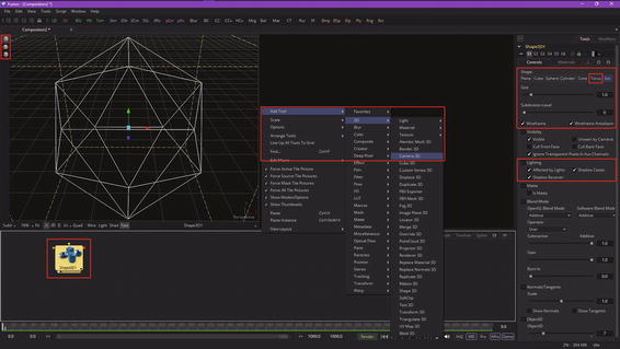
Figure 14-2. Add shape 3D and camera 3D nodes to a new project
Once you have the shape 3D node in the flow node editor, either drag it into View1 to set that view to that node (a cool trick) or click the left dot in the bottom of the tile as shown in Figure 14-2 circled in red. You can move, rotate, and scale this object using the three icons on the top left of the view, or use the Q-W-E keyboard shortcuts. Figure 14-2 shows your move widget in the viewport; click and drag on the colored arrowheads to move the object in that particular direction (X, Y, or Z) in 3D space.
I also circled the torus option in red, as we’ll be using this later on when we cover lighting. A torus, which is like a doughnut, gives us a far more complex inside and outside surface to show off the lighting effects of something like a spot light.
Next, let’s take a look at the camera 3D node and Fusion camera system, as nothing in a 3D scene will render without using a camera!
Camera 3D: Using a Camera to Photograph the 3D Scene
One of the challenges for 2D and 3D compositors is matching the cameras used in live-action shots to the cameras used in the 3D content that is being seamlessly composited into those scenes. To allow you to succeed at these challenges, Fusion provides a flexible virtual 3D camera functionality where you’ll configure common camera controls such as the angle of view, focal length, plane of focus (depth of field), aperture, and clipping planes. These are shown in Figure 14-3 and allow you to set up your own virtual camera that matches the camera you are using for your live-action shots. You can also import cameras from 3D software. Figure 14-3 shows a camera 3D node and control panel.
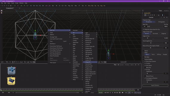
Figure 14-3. Select camera 3D node to see control panel options
When adding a camera 3D node, you must connect it to your merge 3D node in order to view those 3D elements also connected to that merge 3D node, which we will cover in the next section. This node is added using Add Tool ➤ 3D ➤ Merge 3D, as is seen in Figure 14-3 along with a selected camera node and its options.
To view a 3D scene through a camera, select the merge 3D node that the camera is connected to, or any tool downstream of the merge 3D node. You can also drag that selected merge 3D node, or any downstream node (tool), into a viewer. Alternatively, you could use the view-select dots at the bottom of the tool node tile.
If you have more than one camera, you can right-click on the axis label in the bottom corner of the view and choose the camera name that you want to view.
Next, let’s take a look at a merge 3D node tool tile and how it allows us to build a scene.
Merge 3D: Assembling the 3D Scene Components
You’ll notice that the merge 3D node has only one option, which we will select, to pass through the lighting information, which is shown highlighted in red on the right side in Figure 14-4. I am also showing the Add Tool ➤ 3D ➤ Renderer 3D menu sequence to save on the number of figures used. These are the four nodes that are a minimum requirement for creating a 3D Fusion scene.
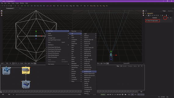
Figure 14-4. A merge 3D node aggregates all the other 3D nodes
Every 3D tool in Fusion will output a complete 3D scene, so that the 2D/3D VFX compositor has the maximum flexibility in creating any visual effect. This is why your merge 3D node tool has this name, as it is merging anything connected to it into the same 3D scene, kind of like a 3D consolidator.
Unlike “traditional” 3D modeling and animation software, where 3D objects occupy the same (global) 3D scene environment, Fusion 3D scenes are created using a camera 3D tool and Merge 3D tool in conjunction with each other.
A merge 3D tool makes this possible by taking attributes of the 3D tools plugged into it and combining them into a single 3D scene data–processing pipeline. Unlike a 2D merge tool, your Z-order of 3D objects in a scene is not restricted to just your background and foreground inputs.
Your merge 3D node allows an unlimited number of 3D data inputs, combining them according to their absolute positions in 3D space. A merge 3D node includes a unified 3D transformation, which is accessed via a tab seen circled in red in Figure 14-4.
Your unified 3D transformation parameters should be used to adjust the position, scale, and rotation of all the elements that you have combined using that particular merge 3D node.
Therefore, it could be considered to be a 3D scene transform utility panel! A global transformation algorithm will not only be applied to 3D geometry, but also to lighting, effects, and 3D particles. All transformations will take place around the scene (environment boundary) pivot point. This pivot point forms the basis for relative 3D object parenting in your 3D environments.
Next, let’s take a look at how to convert your merge 3D scene data into 2D data that can be processed by Fusion’s other VFX pipeline processing tools, many of which I covered earlier.
Renderer 3D: Converting the 3D Data for Use in 2D Compositing
Once you’ve added the renderer 3D node to your basic 3D Fusion scene and wire the output from the merge 3D node into it, you will get a white (flat or “blown out”) representation of the 3D ISO object when you select View2 (white dot) at the bottom of the tile. This is shown circled in red in Figure 14-5, along with the next Add Tool ➤ 3D ➤ Light ➤ Spot Lightcontext menu and the “Enable Lighting” checkbox to enable the lighting, which we will be adding next to get more realistic 3D render results. When you click the “Enable Lighting” option, the white in View2 will turn black, because there is not any light added to the 3D scene yet. Let’s look at how to add light to the 3D scene next.
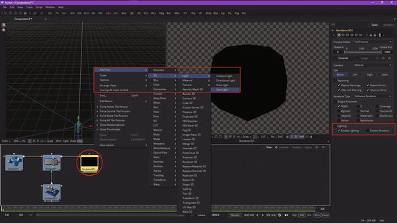
Figure 14-5. The renderer 3D tool converts 3D data into 2D data
Adding Lighting: Add Spot Light Node to Give 3D Primitives Depth
Select the spot light node , as shown in Figure 14-6 at the left bottom circled in red, and set the spot light color to a purple-pink hue, as shown at the top of the control panel. Play around with the decay type, decay rate, cone angle, penumbra angle, and dropoff setting to get a feel for how the spot light tool works. I changed the 3D primitive I was using to the torus primitive to get a better lighting result, as you can see in View2 in Figure 14-6.
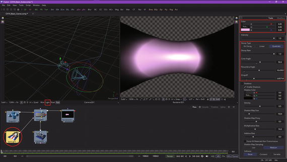
Figure 14-6. Add a Spot Light node and wire it into the Merge 3D node
You can add multiple light sources to a merge 3D (scene) to build highly detailed lighting environments. As you will see in Figure 14-7, I have added a directional light nodeand also turned on the wire modeand light mode, as seen circled in red.

Figure 14-7. Add a directional light, turn wire and light modes on
Your context-menu sequence to add this node tool tile is Add Tool ➤ 3D ➤ Light ➤ Directional Light, so add that to your basic 3D scene project to see how this light works.
There are four different types of lights you may use for your 3D scenes, including ambientlight (global illumination), directional light (along one axis), point light(like a lightbulb), and spot light (like a flashlight). The default light will be a directional light, unless you add your own custom lighting. The lighting won’t be visible in a 3D viewer unless a Light button is enabled in the viewer toolbar. Light would not be visible in a renderer 3D node until an “Enable Lighting” checkbox is checked in the control panel, as seen highlighted in Figure 14-5. Tools that create or load geometry include similar lighting options.
A viewer toolbar Light button can be used to turn lights off or on. If lights are disabled in a viewer or final render, then your 3D imagery will be evenly lit using ambient light. As you have seen, this could make 3D geometry appear flat and less realistic, which is why we’re covering custom lights in detail!
You can use ambient light to set minimum levels of light for your merge 3D scene, because ambient lights create general, or uniform, illumination for any given 3D scene. Ambient light simply exists everywhere, without appearing to emanate from any particular light source, and has no “real-world” equivalent; it is purely a 3D phenomenon. Ambient light can’t cast shadows, and it will fill in the shadow areas within a scene the brighter it is set. I tend to either not use ambient light, or keep it low.
Directional lights, on the other hand, use parallel rays of light. These illuminate the entire scene from one direction, creating a plane of light travelling along one axis. The sun is one example of a directional light source, since it is far away (it is actually a point light source, which we will cover next). The moon is a better example, as it reflects the sun, which “parallelizes” the sun’s rays, making the photons of light travel parallel to each other. Want proof of this? Look at your shadow during the day (blurry edges) and then look at it during a full Moon (crisp, razor-sharp edges), when the Moon is serving as a large reflector, and parallelizing the Sun’s rays. Things like this are why we want to control shadow softness, which we will cover a bit later on. Figure 14-8 shows a torus in wireframe mode, with a directional light moved above it and rotated 90° so it shines down on the shape.

Figure 14-8. Move directional light above torus and rotate 90°
I colored this directional light gold so that you can see the difference between the spot light and the directional light. If you compare Figures 14-7 and 14-8 you can see that the directional light illuminates more of the torus wireframe mesh.
Continuing on, a point light is a light source that will emanate from an infinitely small point in 3D space. The example of a point light from your everyday life would be a light bulb.
A spot light is a more complicated point light that has settings that allow you to produce a well-defined cone of light featuring a brightness fallofffrom the middle of the light to the edges. An example of a spot light would be a flashlight. The spot light in Fusion is the only light that can produce shadow results. In other 3D software, point lights will also create shadows, as will directional lights in many 3D applications.
A Fusion 3D tool that generates or imports geometry has additional lighting options based on unique attributes for that tool. These lighting options will be used to determine how that 3D object will be rendered using lights and shadows in a scene. For instance, if the “Affected by Lights” checkbox is active, the lights in the 3D scene can affect the 3D geometry in the scene. If the “Shadow Caster” checkbox is active, an object will cast shadows on other objects in the 3D scene. If “Shadow Receiver” is active, an object should be able to receive shadows cast by shadow caster enabled 3D objects. These options are highlighted in red in Figure 14-2 in the control panel for the shape 3D node tool in the Lighting section, which I opened and highlighted in anticipation of this topic. Similar lighting control options are available in other 3D tools.
Advanced Lighting: Shadows and Shadow Maps
Let’s take a look at shadows in Fusion, and along the way I will show you some of the cool user interface options in the 3D compositor part of Fusion. The first thing we’re going to do is to add an image plane 3D node using Add Tool ➤ 3D ➤ Image Plane 3D, as shown in Figure 14-9. We will select the spot light node and adjust the parameters to get rid of the white “hot spot.” Also, we will make sure that the “Enable Shadows” option is selected, as shown in Figure 14-9 on the right inside of the red box highlighting.
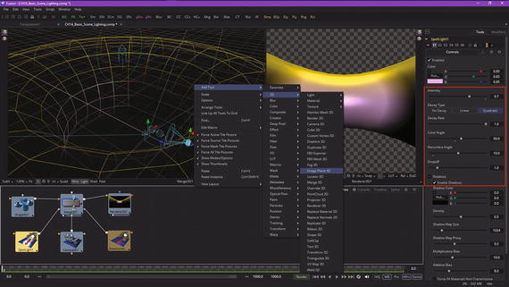
Figure 14-9. Add an image plane 3D Node and adjust a spot light
Now the torus mesh wireframe has a nice pink (spot light) and gold (directional light) coloring, showing you where those lights are hitting the object. This is a great technique (colored lights, at first) to use to show you where lights are affecting your 3D geometry, before your materials and textures are added, at which you would most likely switch light colors back to white.
Next, let’s wire the image plane 3D into the merge 3D so it becomes part of this 3D scene composition, as can be seen in Figure 14-10. Once it is connected, you will see the image plane 3D mesh in the middle of the torus, which you will move later. The image plane 3D control panel settings that lock your aspect ratio (Lock Width/Height) tell how many squares will be in the mesh (10). You can also see a “Wireframe” option you do not need, as the View1 “Wire” option is enabled. Also, open up the Lighting section and make sure that all the lighting and shadowing options have been selected. If there’s no geometry behind the image plane, you can turn the “Shadow Caster” option off to save on rendering processing overhead.

Figure 14-10. Wire the image plane 3D node into a merge 3D node
Next, select the move icon and use the blue z-axis arrow head to move the image plane outside of the center of the torus, as shown in Figure 14-11. The widget axis you are using will turn white to show that it is in use. The move icon is seen in red in the upper-left corner, and the image plane is now inside of the torus, as you can see in your renderer 3D node View2.

Figure 14-11. Use a move widget to move the plane on the z-axis
We need to move the image plane further, so let’s switch into Quad View mode by clicking the Quadbutton shown in Figure 14-12. Each of the four views supports its own wire and light mode settings, which is why the active right view has wire selected.

Figure 14-12. Turn on Quad View, and move the plane out of the inside of the torus
Now I can see the torus and plane in white. I use a move widget to put the plane outside of the torus, then switched to the Front view, as seen in Figure 14-13, so I could scale the plane up using the scale slider in the settings shown circled in red. “Lock XYZ” is another way of saying “Lock Object 3D Aspect Ratio.”

Figure 14-13. Move a scale slider in the image plane control panel
Now you can see the plane behind the torus in View2, as in Figure 14-14. I selected the Material tab , seen on the right in red, and selected the “Receives Lighting” and “Receives Shadows” checkboxes, as well as made sure the plane used a white color.

Figure 14-14. Use the Material tab to enable light and shadows
Next, turn off Quad View mode. Let’s look at how you can selectively choose the different views in a single view mode by using the right-click context menu and then selecting Camera ➤ Right to set the right view. This way, we can start to position the camera to look down on the plane in order to see the shadowing effect.
Select the camera and the move icon, highlighted in red in Figure 14-15, and move your camera above the torus, as shown in the middle. The new renderer 3D View2 can be seen on the right; it shows the new positioning for the camera.
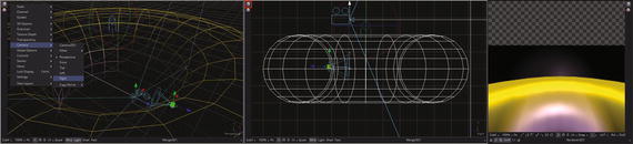
Figure 14-15. Use move icon with y-axis arrow to move camera up
Next, select a rotate icon, highlighted in red in Figure 14-16, and use an X-rotation ring to rotate the camera forward.

Figure 14-16. Use rotate’s X-rotation ring to point the camera down
Although this fat torus and plane are fine for showing a lighting simulation, we really need a thinner torus that is 75° from where it is now, or nearly parallel to the plane, so it’ll cast a nice oval shadow, as seen in View2 in Figure 14-17. Move your spot light up and your camera down, as shown in Figure 14-17, and rotate them so that they will cast a nice shadow. Set your torus characteristics to radius 0.6, section 0.1, a subdivision base of 32, and a subdivision height of 24. I also colored the torus army green to make it stand out a bit better. Finally, I selected the renderer 3D node tile and made sure the “Enable Lighting” and “Enable Shadows” options had been selected.

Figure 14-17. Rotate and scale the torus to better cast shadows
Next, I zoomed in 200 percent on the renderer 3D View2 so I could see the shadows better and then centered the view using middle mouse button panning. I also used left + middle button zooming to zoom into my merge 3D View1 so you can see the camera and spot light positioning more clearly and mimic them in your own Fusion project.
As you’ll see at the top of the spot light control panel in Figure 14-18, I have increased the intensityof the spot light to 100 percent, selected the No Decayalgorithm, set Dropoffto zero, and maxed out the cone angleand penumbra angleto get solid white lighting on the image plane 3D object so as to better show the shadow effect and to more clearly show the different shadow settings.

Figure 14-18. Pan and zoom renderer 3D view 200 percent to see shadows
As you can see, I used the default settings for the shadow effect shown in Figure 14-18, which gives a realistic result. I selected the “Variable Softness” option to expose the controls for spread, minimum softness, and filter size, as these are advanced settings that you will need to know about to create realistic VFX pipelines and believable 3D compositing results. Let’s look at key shadow parameter options in detail to see what they do.
The shadow map parameters are seen in the middle section highlighted in red in Figure 14-18. Shadow densitycontrols how dark the shadow is, as shown at 75 percent (0.75) in Figure 14-19.
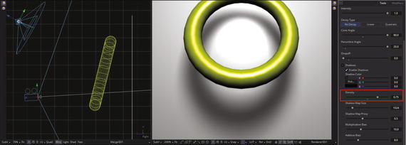
Figure 14-19. Set shadow density to 0.75 to get darker shadows
This control affects all of the other shadow settings—a global parameter, if you will. The other parameters affect only particular attributes (characteristics) for shadow properties , so these are more local, or fine-tuning, parameters, if you will. Let’s take a look at them next, as their effect is less evident.
A shadow map is a type of depth map that specifies each pixel’s depth in a scene. The depth information is used to create a shadow layer using the spot light settings. The shadow quality is inversely related to the size of the shadow map. Larger maps would generate higher-quality shadows, taking longer to render. Let’s reduce the shadow map size200 percent to 338 and take a look at the decrease in quality in the renderer 3D View1, as is seen in Figure 14-20. As you can see, the quality is literally terrible!

Figure 14-20. Reduce shadow quality; set shadow map size to 338
The wider the cone of the spot light, or the more falloff you set for the cone, the larger your shadow map needs to be to obtain high-quality results. As with anything, there is a point of diminishing return, where increasing shadow map size doesn’t improve visual quality for a shadow. Do not set shadow map size to be any larger than it needs to be as a processing optimization. A shadow map proxycontrol can be used to set the percentage that a shadow map is scaled for fast interactive previews, but it does not affect quality, as you can see in Figure 14-21, where it is set at 100 percent.
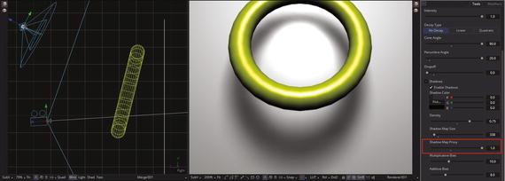
Figure 14-21. Shadow map proxy doesn’t affect quality (it darkens shadow)
Multiplicativeand additive biaswork by adding a small depth offset. This moves your shadow away from the surface that it’s shadowing, eliminating something called Z-fighting. When small bias values are used, as shown on the left side in Figure 14-22, 3D objects will “self-shadow ” themselves. When high bias values are used, shadows become separated from the 3D surfaces.

Figure 14-22. A range for multiplicative bias and additive bias
Shadows can be viewed as textures applied to 3D objects in a scene. This can result in Z-fighting, which results when a portion of a 3D object that should be receiving shadows renders on top of that shadow. When this happens, adjust the multiplicative bias until the majority of this Z-fighting is eliminated, then adjust the additive bias slider in order to eliminate the rest.
The spot light includes a softnessfeature, with options of Constant, Variable, or None, as seen in the bottom red box in Figure 14-18. Hard-edged shadows, set using None, render significantly faster than the other, softer shadow options. Hard-edged shadows would be jagged or aliased, unless your shadow map size is large enough. Shadow softness can be used to hide aliasing, rather than using large shadow maps to preserve memory and optimize for the GPU.
The Constant softness option will generate shadows where edge softness will be uniform across a shadow regardless of the shadow distance from the 3D geometry that is casting that shadow.
The Variable softness option will generate shadows that get softer the farther they get from 3D geometry that’s casting the shadow. This is more realistic for visual effects; however, your shadow characteristics are more difficult to specify. When the Variable option is used, three additional controls, seen in Figure 14-18, allow for adjustment of spread(falloff), minimum softness, and filter size.
Increasing the filter size increases the maximum allowed softness for that shadow. Decreasing the filter size reduces render time, and might limit the softness of the shadow or potentially even clip the shadow. This value is a percentage of shadow map size.
A “Force All Materials Non-Transmissive” checkbox controls how light should pass through a semi-transparent material. This can play an important role in determining the appearance of the shadow that a 3D object casts.
Normally, this transmittance behavior will be defined in a 3D object’s Material tab. You should override this by selecting “Force All Materials Non-Transmissive” in your spot light control panel. This will cause a shadow map produced by your spot light tool to ignore all transmittance behaviors for your 3D objects.
As you might have surmised, you will need to practice and experiment with all of these nodes, tools, and settings quite a bit before you will really become comfortable with them. The 3D components of Fusion are inherently complex—as 3D software can tend to be—and take some experience to master completely. But it is well worth it, especially where your VFX project pipeline is concerned, as it can help you achieve both realism as well as the wow! factor in your work which will set it apart from the crowd.
Summary
In this fourteenth chapter we took a look at the 3D compositing concepts, principles, and capabilities available in Fusion 8. We looked at 3D geometry tools, camera 3D, lighting, and shadows. We found out how to use a merge 3D node to create 3D scene aggregations, and at how to use a renderer 3D node to turn these from 3D data into 2D data.
In Chapter 15, you will learn about advanced 3D topics, such as surfaces, materials, shaders, textures, special effects, and other concepts and techniques we didn’t get around to during this chapter. Fusion 3D compositing is a complex topic, and it will in fact take the next several chapters to cover all of the important 3D features available for use in your VFX project pipelines.