Now that you have an understanding of the fundamental concepts, terminology, principles, and methods of data footprint optimization for your digital imagery, digital audio, and digital video new media content, it’s time to get into 2D and 3D vector new media in this and the following chapter. Fusion supports one open source 2D vector format called SVG, or Scalable Vector Graphics, so that will make things easy. We can focus on SVG concepts and terminology in this chapter, as both GIMP and Inkscape support SVG. Then, in the next chapter, we can take 2D vector imagery into the third dimension with 3D vector imagery.
We’ll look at how a digital illustration is created using points in 2D space, lines and curves connecting those points to create shapes, and color fills, gradients, or patterns inside of these 2D vector shapes. We will look at the open source digital illustration SVG data file format, which is supported by Fusion as well as other open platforms, like Android, Java, and HTML5.
Digital Illustration Is Rendered, Not Stored
As you learned in Chapter 2, pixel-based digital imagery is technically called raster imagery, because an array of pixel values is rasterized to a screen, thus displaying the image created using these pixels. Digital illustration, or vector imagery, is not stored as an array of image elements (pixels). It’s instead drawn, or rendered, to the screen, just like you would draw it if someone were watching you draw, only using instructions that the computer uses to do exactly what you did when you created it. This is the equivalent of the MIDI concept you learned about in Chapter 4, where the performance—in this case it is drawing; in that case it was composing music—is recreated by the computer processor, which renders it to the screen (SVG) or synthesizer (MIDI) using playback instructions.
With vector images, this is accomplished with coordinates in the 2D X,Y space, along with mathematics that define curves, which are conveyed using SVG instructions that look a lot like code. We will cover the basic constructs of vector illustration first so you understand how it all goes together. After that, we will look at how the SVG format turns these into instructions that can be processed in Fusion, Android, Java, or JavaFX using SVG-compatible classes. SVG can also be processed by HTML5 and CSS.
Vector Components: Vertices and Curves
Digital illustration vector images are composed of points using coordinatesin 2D space, and lines or curves that connect those points together. We will be looking at concepts and terminology for these points and lines during this section. If you create a closed shape—that is, one where there are no openings through which a fill (color, pattern, or gradient) can escape—you can fill the vector shape so that the shape looks solid instead of empty.
The Vertex: The Foundation for 2D Shapes
The foundation for any 2D or 3D vector asset is called a vertex. Multiple verticesare required to create a line or arc, which require two vertices, or a closed shape, which requires at least three vertices, unless you are using curves, in which case you can do it with only two. Vertices are used in both 2D vector (SVG) data processing and 3D vector (OpenGL) data processing, both of which are integrated into Fusion 8.
Vertex data is outlined in SVG using X,Y coordinates, as you might have guessed, which tell the processor where a vertex is located in 2D space. Without these vertex coordinates, lines and curves cannot be drawn, as they must have an originas well as a destinationvertex coordinate as part of the line-drawing operation. Lines and arcs are examples of open shapes.
When we get into creating and looking at SVG data, you’ll notice that these X,Y numeric pairs make up the majority of the SVG data, which can be contained using the XML format, or in a Java SVG object for Android. SVG data can be used in your JavaScript (HTML5) code as well as in JavaFX (Java 8 or Java 9) code; thus, it is compatible across each of these open-platform application development workflows, including your VFX processing pipeline.
An X,Y coordinate all by its lonesome is what is termed one dimensional, or 1D. It takes two vertex coordinates to be considered two dimensional, or 2D, so a line or a curve—that is, an open shape—or a closed shape will be considered a 2D object.
The Path: Connecting Vertices to Create a Shape
A path is defined in SVG using a “path” data element. Both an open shape and a closed shape are technically a path, according to the SVG specification. An SVG pathrepresents the outline of an open or closed shape that can be filled, stroked, or used as a clipping path. We will be covering these concepts in detail during this chapter, but in short a fill deals with the interior of a path, a strokedeals with the lines or curves that make up a path, and a clipping pathis used for Boolean operations.
In SVG data an SVG path object represents 2D geometry used to outline a path object. In fact, in JavaFX, the class is actually called the SVGPath class! SVG path data can be defined in terms of SVG commands, which I will outline later in the chapter using Table 5-1. Some of these include a moveto command , which sets your current point; a lineto command , which draws straight lines; a curveto command, which draws cubic Bézier curves ; the elliptical arc command , which draws an elliptical arc; and the closepath command , which closes a current shape, drawing a line to its starting point. There are also advanced SVG commands.
Table 5-1. SVG Commands You Will Use for Creating SVG Path Data
SVG Command | Symbol | Type | Parameter | Description of the SVG Command |
|---|---|---|---|---|
moveto | M | Absolute | X, Y | Define a Start of Path, at the X,Y coordinate, using absolute coordinates |
moveto | m | Relative | X, Y | Define a Start of Path, at the X,Y coordinate, using relative coordinates |
closepath | Z | Absolute | None | Close SVG Path, by drawing line, last to first point |
closepath | z | Relative | None | Close SVG Path, by drawing line, last to first point |
lineto | L | Absolute | X, Y | Draw Line from the current point to the next point |
lineto | l | Relative | X, Y | Draw Line from the current point to the next point |
horizontal lineto | H | Absolute | X | Draw Horizontal Line from the current point to the next point |
horizontal lineto | h | Relative | X | Draw Horizontal Line from the current point to the next point |
vertical lineto | V | Absolute | Y | Draw Vertical Line from the current point to the next point |
vertical lineto | v | Relative | Y | Draw Vertical Line from the current point to the next point |
curveto | C | Absolute | X,Y, X,Y, X,Y | Draw a cubic Bézier curve from the current point to the next point |
curveto | c | Relative | X,Y, X,Y, X,Y | Draw a cubic Bézier curve from the current point to the next point |
Short and smooth curve | S | Absolute | X,Y, X,Y | Draw a short cubic Bézier curve from the current point to the next point |
Short and smooth curve | s | Relative | X,Y, X,Y | Draw a short cubic Bézier curve from the current point to the next point |
quadratic Bézier curve | Q | Absolute | X,Y, X,Y | Draw a quadratic Bézier curve from the current point to the next point |
quadratic Bézier curve | q | Relative | X,Y, X,Y | Draw a quadratic Bézier curve from the current point to the next point |
short quadratic Bézier | T | Absolute | X,Y | Draw a short quadratic Bézier curve from the current point to the next point |
short quadratic Bézier | t | Relative | X,Y | Draw a short quadratic Bézier curve from the current point to the next point |
elliptical arc | A | Absolute | rX, rY, Rot | Draw an elliptical arc from the current point to the next point |
elliptical arc | a | Relative | rX, rY, Rot | Draw an elliptical arc from the current point to the next point |
Compound pathsare also possible in SVG; these allow you to create complex, Boolean-shape special effects. For instance, you could use a compound path to create a hole in your shape.
These SVG paths can be used in Fusion to create a vector asset or to define other, more advanced things like interpolation.
Lines: The Simplest of the Path Components
The simplest way to connect point coordinates along a path is to use straight lines. Different shapes such as triangles, squares, pentagons, and hexagons can be created using the lineto (L) commands. There are three lineto commands: lineto, horizontal lineto, and vertical lineto, as outlined in Table 5-1.
To code an octagonusing SVG, you would use a moveto (M) command from a point (vertex) at 60,0 and then draw seven lines using lineto commands. This would look like the following:
M 60 0 L 120 0 L 180 60 L 180 120 L 120 180 L 60 180 L 0 120 L 0 60Next, let’s take a look at the elliptical arc, which is a simple curve by nature with a complex set of specification data for its SVG command. This is why I usually stick with curves, from a modeling perspective, as you can create 2D paths using fewer data points (vertices) than with elliptical arcs. This is far more data optimized. This also holds true for 3D models, where polygon models that use straight lines (edges) are more data intensive, as they use more points and lines to represent a curved surface than mathematical formulas for an actual curve will utilize.
Elliptical Arcs: Circular and Elliptical Arcs
The elliptical arc uses a capital A (absolute) or lower-case a (relative). The arc command draws a segment of an ellipse. It takes the largest number of parameters of any of the curve drawing-related commands and takes the following basic format:
M x,y A rx,ry x-axis-rotation large-arc-flag sweep-flag x,yHere, M (moveto) x,y is your starting pointfor the arc, rx is the x-radiusfor the ellipse, ry is the y-radiusfor this ellipse, and x-axis-rotation is the number of degrees to rotatethe x-axis. There are two on/off flagsfor large/small arc and sweep/no-sweep arc, and the final x,y coordinate is the end pointfor the arc.
It is important to note that setting both the x radius and the y radius (the rx and ry values) to identical values will create a circleinstead of an ellipse, as this makes the curvature symmetrical.
The example I found online that is shown in Figure 5-1 allows you to modify whether your arc coordinates are absolute (A) or relative (a) to the starting point (defined by the red blob). An example of the following M 125,300 A 225,100 0 1 1 375,300 elliptical arc command and coordinate sequence shows how an arc can be defined. If you want to include the missing segment for the ellipse at the bottom, you will deselect, by setting to zero, the large arc flag and the sweep flag, which should draw the smaller part of the arc and mirror it around an x-axis. The command for this should look like the following: M 125,300 A 225,100 0 1 1 375,300.
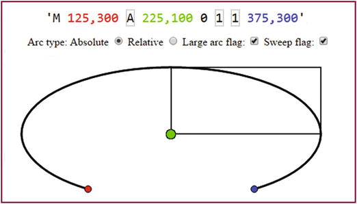
Figure 5-1. Elliptical arc with sweep and large arc flags on
As you can see, these rx,ry parameters create different angles, which distort your ellipse from being a circle into being an elliptical shape. There are several SVG curve generators on the Internet if you want to experiment with these parameters more.
Cubic Bézier Curve: Two Curvature Control Points Are Available
If you have ever used the Pen tool in Photoshop or GIMP, or used Inkscape, or any of the 3D modeling tools out there, then you are probably familiar with Bézier curves. I am not going to go into all of the math behind how curves are constructed mathematically, as this is a VFX fundamentals book and not an advanced book, but we will be looking at how to use open source tools to generate the digital illustration vector assets you will need for your Fusion VFX project pipelines. In a nutshell, you would draw cubic Bézier curves, using SVG commands, by defining your start and end points as well as two control points—one control point for the start point and one control point for the end point. These control the curvature of a curve (also called a splinein the industry) that is going away from the first data point and coming into the second data point.
The cubic Bézier curve command would utilize the following format:
M x,y C (or c) x1,y1 x2,y2 x,yThe starting point is defined by M x,y, and the C (or c) defines an absolute or relative cubic Bézier curve type. The x1,y1 is your control point for beginning the curve, and x2,y2 is your control point for end of curve. Finally, your x,y coordinate at the end of the command string is an end point for the cubic Bézier curve. You can create this Bézier curve in real-time by using the popular open source Inkscape software. A Bézier curve can also be used in Fusion 8 for controlling data related to timing, transitions, and similar effects applications.
Quadratic Bézier Curve: A Single Curvature Control Point Used
Your inclination will be to assume that quadratic Béziercurves are more complicated, given that quad means four, and thus there are even more control points for this type of curve. However, the exact opposite of this is actually the case, because a quadratic Bézier curve actually has only one control point that connects to both the start and end point of the curve segment! Moving this point controls how a curve is shaped between the two points. So, if you are looking for a coordinates data reduction of 100 percent, as far as control-point specification goes, use quadratic Bézier curves. An SVG command specification for a quadratic Bézier curve will thus look like the following:
M x,y Q (or q) x1,y1 x,yNote how the quadratic Bézier command requires only one single control point, which is then used as the control point for both start and end points. It’s like the two control points in a cubic Bézier curve are connected as one control point that moves the curvature from the start point and into the end point at the same time. There are numerous SVG curve generators on the Internet if you want to experiment with the parameters.
The Fill: Filling Your Closed Shapes with Colors
Once you have defined your shape using lines, arcs, and curves, you can fill it to make it solid rather than hollow or empty. A fill can be a color, a gradient, or a tiling image pattern. You can fill an open shape if you like, and the (imaginary) line connecting the start point with the end point will define the fill boundary so that the fill does not go all over the place in your digital illustration. The fill operation, as well as the stroke operation, which we’ll cover next, is what is known as a paintoperation. Fusion 8 has extensive painting capabilities, so you may want to use SVG for 2D curve creation and Fusion for the painting operations.
Color Fill: Filling Your Shape with a Solid Color Value
To fill the octagon we looked at earlier in the line section with green, a fill="green" statement would be added after the data statement that creates the shape. Using SVG XML, these two declarations would be inside of a path XML tag using the following XML markup SVG data structure:
<path>d = "M 60 0 L 120 0 L 180 60 L 180 120 L 120 180 L 60 180 L 0 120 L 0 60"fill = "green"</path>
Solid fill color is not as useful as gradients, however, as careful use of gradients can simulate a 3D result using 2D SVG graphics. Defining a gradient is more complex, so let’s take a look at linear and circular gradients next.
Gradient Fills: Linear Gradients and Radial Gradients
There are two types of gradients in SVG, a linear gradientand a radial gradient. A linear gradient is the most common type of gradient that you will encounter, so we’ll start with that type first. Much of what applies to how a linear gradient is set up will also apply to the radial gradient, which simply uses a different XML tag. I will show you how to set up a <linearGradient> tag using SVG in XML, and you can simply change it later to be a <radialGradient> to change your gradient type.
Gradients are defined in the <defs> or definitions tag in SVG XML. The <defs> tag goes inside the parent <svg> tag, and has the <linearGradient> tag as its child tag. Inside the <linearGradient> tag are two <stop> child tags. Stopsare used to define the colors in the gradient, what percentage they take up in the overall gradient, and alpha (transparency) values for that section of the gradient. There must be at least two stops, and you can use any number of gradient sections that you need.
Make sure that your stop offset values add up to 100 percent in the end. Here is how you would fill your octagon with a red and yellow linear gradient; as you can see, it’s much more complex than the octagon example:
<svg xmlns='http://www.w3.org/2000/svg' height="300" width="300"><defs><linearGradient id="LinearGradient" x1="0%" y1="0%" x2="100%" y2="0%"><stop offset="0%" style="stop-color:rgb(255,255,0);stop-opacity:1" /><stop offset="100%" style="stop-color:rgb(255,0,0);stop-opacity:1" /></linearGradient></defs><path>d="M 60 0 L 120 0 L 180 60 L 180 120 L 120 180 L 60 180 L 0 120 L 0 60"fill="url(#LinearGradient)"</path></svg>
You wire the gradient into your fill using the id="name" parameter inside of the <linearGradient> tag and then reference that name inside of your fill="url(#name)" parameter inside of your <path> tag, as can be seen in the previous SVG XML markup.
Pattern Fill: Filling Your Shape with a Tileable Image Pattern
Patterns are also defined in the <defs> or definitions tag in SVG XML. The <pattern> tag goes inside the parent <defs> tag, and it has the <image> tag as a child tag. Inside the <image> tag is a reference to and specifications for the image asset. Patternsare seamless image tiles that fill a shape with a 2D texture map. We will be learning more about texture maps in Chapter 6, which will cover 3D vector concepts and terminology.
Make sure your pattern width and height values match up with your image width and height values. The image x and y position the start of the pattern at the upper-left corner, which is always location 0,0. Here is how you would fill your octagon with an eight-pixel tiling image pattern; as you will see, it’s an even more complex definition than your gradient:
<svg xmlns='http://www.w3.org/2000/svg' height="300" width="300"><defs><pattern id="pName" patternUnits="userSpaceOnUse" width="8" height="8"><image xlink:href="data:image/filename.png"x="0" y="0" width="8" height="8"></image></pattern></defs><path>d="M 60 0 L 120 0 L 180 60 L 180 120 L 120 180 L 60 180 L 0 120 L 0 60"fill="url(#pName)"</path></svg>
I am showing you how to do this because even though this is a VFX fundamentals book I want to include some complexity, as VFX is a complex undertaking and topic. A large percentage of Apress titles are targeted for programmers or developers, so I’m covering SVG, XML, HTML5, JavaFX, Java, and Android. Many of you would use software such as Inkscape to create vector artwork, and then export it to SVG.
At the end of the workday, however, you’ll need to know how to bridge the SVG command structure with the Fusion project pipeline, and possibly later with application code, so I’m going to cover the basic SVG commands during the chapter so that you have knowledge of SVG basics for VFX applications development.
The Stroke: Controlling How Lines and Curves Look
Finally, let’s take a look at how to stroke—or color, style, or thicken—the lines, arcs, or curves that you created using these SVG commands. The stroke parameters allow you to define stroke color, opacity, width in pixels, dash array pattern, and how lines will be capped or joined together using round, square, or bevel constants. Let’s add these stroke-related parameters to a <path> we created earlier for the octagon and give it a three-pixel-thick black border with round corners, a dashed line, and 50 percent opacity. This is accomplished via the following SVG XML markup:
<path>d = "M 60 0 L 120 0 L 180 60 L 180 120 L 120 180 L 60 180 L 0 120 L 0 60"fill = "green"stroke = "black" stroke-width = "3" stroke-dasharray = "5, 10, 5"stroke-linecap = "square" stroke-linejoin = "round" stroke-opacity = "0.5"</path>
Next, let’s finish up by looking at the primary SVG data commands that you’ll be using when creating 2D vector assets for your Fusion 8 projects, probably by using GIMP and Inkscape.
SVG Format: Coding Vector Shape Data
There are ten different letters that can be utilized with the numeric (X,Y data point coordinate location) data in SVG data strings. Each has an uppercase (absolute reference) and lowercase (relative reference) version. As you can see in Table 5-1, SVG data commands provide you with a great deal of flexibility for defining custom curves for your VFX project pipelines. You can even combine all of these scalable vector-graphics SVG commands with code to create interactive vector artwork that has never before been experienced. You can then add the VFX content using the same Java, JavaFX, HTML5, and Android code.
An optimal way to see how to use these powerful SVG data path-drawing commands is to learn a work process for creating SVG data with vector illustration tools and then export work flows. This is possible using GIMP and Inkscape. If you’re a VFX artist, you can use the SVG constructs as control data for non-graphical uses. If you’re interested, I cover 2D vector and SVG further in Digital Illustration Fundamentals (2015, Apress).
Summary
In this fifth chapter we took a look at 2D vector illustration and its related concepts and principles, as well as at the SVG format. We looked at how vertices, lines, arcs, curves, fills, patterns, gradients, and strokes contribute to 2D vector content creation. In Chapter 6, you will learn about 3D vector concepts.