
Now that we have covered the three major VFX editing areas in Fusion 8—Flow, Timeline, and Spline—it’s time to get into some more advanced concepts. The concept of maskingobjects and areas was covered in Chapter 2 when we discussed using alpha channels to define transparency, which isolates the pixels that you wish to composite, blend, or process algorithmically—or all of the above, in some instances.
In still image compositing software packages, like GIMP, PaintShop Pro, or Photoshop, you can draw splines on your images to cut (or mask) out the object or element you wish to isolate. Fusion also uses this approach with what it calls polylines, which are the different types (natural B-spline, cubic Bézier, etc.) of mathematically-derived curve topologies that are supported for use in the VFX software package. We looked at these in Chapters 9 and 10, but we’ll be getting into more detail regarding polylines in this chapter, as we see how to use them as inputs for masking out detailed areas of pixels that we want processed in our VFX composition pipelines. If that isn’t advanced enough, we will also look at how you can animate the masks like you can with morphing and warping software.
In this chapter, we’ll look at polyline types and tools, using polylines for masking and rotoscoping, animating polyline masks, using polylines for motion paths, and double polylines.
Polylines: Masks, Rotoscope, and Motion
You have already seen polylines used in Chapter 9 for a motion path, and in Chapter 10 in your spline editor. Let’s look into the differences between the different polyline (curve) types, and see how they are implemented in Fusion using the floating polyline toolbar that you first saw in Chapter 9 (Figure 9-11). After that, we’ll take a look at how to utilize polyline tools.
Polyline Types: Cubic Bézier and Natural B-Spline
There are two types of control curves used in Fusion currently. One is the standard cubic Bézierused in software such as GIMP and Inkscape, and most other packages that use splines, and the other is the natural B-spline, which is more similar to the quadratic Bézier used in SVG (Scalable Vector Graphics). If you are a 3D modeler you may also be familiar with the non-uniform rational B-spline (NURBS) topology found in 3D modelers such as Moment of Inspiration 3.0. It is possible that other spline topologies could be added to Fusion in the future, especially due to its increasing support (fusion) of 3D-into-2D workflows.
Bézier Polylines: Two Tensioning Handles for Each Control Point
The Bézier polyline is used the most widely in Fusion 8, in the flow node editor (view panes), timeline editor, and spline editor, as we saw in Chapter 10. When Bézier handles are retracted (or are tangent to their control curve ), they create a polygonal (straight) line control curve (open) or closed shape, as seen in the spline editor on the left side of Figure 11-1.

Figure 11-1. Bézier polylines can be used in the spline editor
When you pull these control curve tensioning handles out from the spline node or away from your polygon , you create your curvature (curve). Since I already covered a significant number of tools related to Bézier curves in Chapter 10, in this chapter I will cover new aspects of curve modeling so that I can cover as many topics as possible.
B-Spline Polylines: Bounding Cage for Organic (Smooth) Shapes
In most instances , one can achieve the same control curve results using the cubic Bézier topology as they could using the natural B-spline topology. B-splines (especially NURBS) will often be used for organic modeling, where things need to be curved rather than sharp. This is especially true for 3D character modelling .
B-splines cannot do “sharp” or polygonal (straight line) curve transitions, which is why they’re not used in Fusion’s spline (time) editor. Figure 11-2 shows the motion path from your Chapter 10 project. I inserted a control point halfway up and pulled the tensioning handles out to create a more natural, curved path for the jellyfish to follow on its journey to the surface. I then converted this to a B-spline so that you can see the difference. Figure 11-2 shows the Bézier on the left and the B-spline on the right. I pulled a couple of the control cage points away from the curve so you can see how this works more clearly, and to show how a curvature is maintained at all times with this spline topology, eliminating all jerky movements.
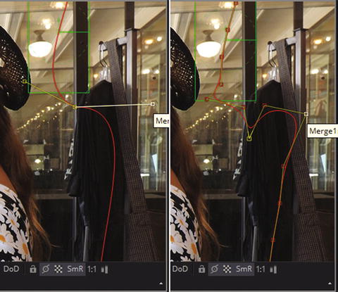
Figure 11-2. Bézier curve converted to B-spline
There are no abrupt transitions or changes in a B-spline like there are at the control point for the Bézier curve, which at the end (bottom) of the top half of the curve instantly goes in a different direction to start the bottom half of the curve.
Your open B-splinecan have control cage handles on both sides of the curve, whereas a closed B-spline(shape) will only have control cage handles on the outside perimeter, which is why this topology may be desirable for use with organic masking shapes used to isolate areas in VFX composites to be processed.
The way you make this topology conversion in Fusion is to right-click on your Bézier spline, as shown in Figure 11-3, and then select the polyline motion path, which in this case Fusion named Path1:PolyLine (Component Name : Component Type). Then, select a Bézier to B-Spline topology conversion algorithm, using the resulting submenu.
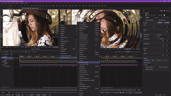
Figure 11-3. To convert topology, use Bézier to B-Spline option
Next, let’s take a look at Fusion 8’s polyline toolbar. We will go back to the Chapter 9 jellyfish composition project and edit the linear motion path from scratch. This project also has linear motion paths in the timeline and spline editors, so I can focus on polyline features starting with polygons, as all curves start out as straight polygon lines until tension handles turn them into curves.
Fusion’s Polyline Toolbar: Working with Polylines
Open the Chapter 9 jellyfish project, and select the right view dot in the merge node, and in the timeline view select that merge node. This will give you the motion path and the polyline toolbar, as shown in Figure 11-4. Select the insert and modifypolyline tool, seen circled in red, and click in the center of the path.
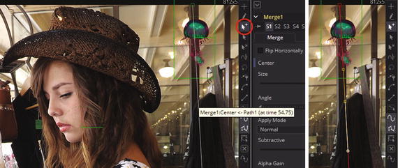
Figure 11-4. To add complexity to a curve, use the insert and modify tool
To maintain the straight polygonal line, your tensioning handles will be tangent to, or parallel with, the original line segment, so you have essentially converted a vector (ray) into a cubic Bézier spline, mathematically speaking, once you adjust those tensioning handles.
Next, mouse-over the bottom handle (it will turn white) and make the spline curved, so that the jellyfish travels more naturally through the composition. Drag the tensioning handles so that the jellyfish motion path has a nice S shape. Use your CRTL modifier key to move the handles independently of each other, and you can position your spline path end points as well using the arrow icon, which edits (but does not add or delete) point locations. This editing can be seen on the left in Figure 11-5.
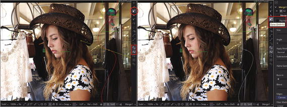
Figure 11-5. Add a point to the motion curve, edit tensioning handles, and select Done
I circled the insert and modify tool, as well as the show key pointsand show all handlestools, which are all turned on, as designated with a lighter gray color. If you want to lock in your motion curve, use the Done option, as seen on the right side of Figure 11-5, which will turn the curve white, and prevent any further editing. If you want to delete points, turn on the icon second from the bottom (it is an X), and if you want to optimize your spline point count, use the reduce pointstool, found at the very bottom of the polyline toolbar. Next, let’s take a look at mask generation (creation) with Fusion, which uses a different set of polyline toolbar icons.
Visual Effects Masking: Selective Pixel Processing
There are several different types of masking that you can do in Fusion 8, including effects masking (also called post-masking ), pre-masking , garbage mattes (also called garbage masking ), and animated polyline masking . The one you’ll use most often is post-masking, where the mask is applied after an effect.
Effect Mask: Applied Post-Effect to Isolate Areas of a Composited Element
Select the Drip1 node in the flow editor, with Niki.png (Input) set to View1, and Merge1 (Composite) set to View2. Right-click View1 and select the Drip1:EffectMask option , then select Polygon mask, as is shown in Figure 11-6.
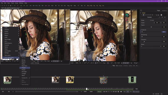
Figure 11-6. Select the Drip1 node and the Polygon effect mask
This will add a Polygon1 mask node tile above Drip1 into the mask input. Select this node, as seen in Figure 11-7, and a polygon mask polyline toolbar will appear in View1 on the left. Click at the top of the hat using the click appendtool used in mask creation (both shown circled in red) and click out a rough outline of the model, as is seen on the right side of the model.

Figure 11-7. Use click append tool to create right half of mask
You do not have to spend a lot of time on this polygonal mask outline; just place vertices where your directional shifts in the mask perimeter occur, as later on you’ll use tensioning handles to make these curve segments conform with an outline of the subject matter you are masking—in this case it is a model.
As you can see in Figure 11-8, once the polygonal cage is all of the way around your model, and you put your last spline point on top of the first spline point, the cursor will change to the close shape symbol, and the word Polygonwill pop up in a tool tip, as shown at the top of Figure 11-8. Click to close the polygon, and a black and white representation of your mask will appear inside of your Polygon1 node tile’s preview area, which you can see in Figure 11-9.
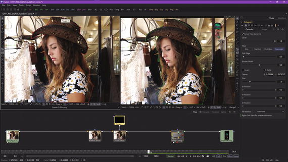
Figure 11-8. Use click append to finish mask, and then close polygon
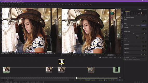
Figure 11-9. A closed polyline mask now shows in the flow node tile for your mask node
Now you’re ready to refine your polygonal mask, making it into a polyline mask —or a Bézier mask, more precisely—by selecting the arrow (point select) tool. Or, you can use the add point tool, as long as you only click on your points to select each one for editing. Use the handles to adjust the curvature of the polygon, point by point, until it fits snugly.
As you can see in Figure 11-9, I have turned all of the straight lines into custom curves, and this polyline mask edge-fits the model fairly nicely at this point. You can continue to refine your point placement and tensioning handles if you like.
Next, drag a wire (pipe) from the Polygon1 mask node into the BlurNiki node mask input. As you can see in Figure 11-10 in View2, your mask now defines where your effects will be applied.
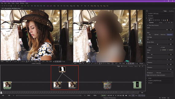
Figure 11-10. Wire the polygon mask node into the BlurNiki node
Play the effect in the timeline, as shown in Figure 11-11.

Figure 11-11. Drag the playhead and animate the masked effect
As you can see, a polyline mask now constrains the effect processing pipeline to the model herself, and leaves the store around her intact and unprocessed. You could combine this with a fade, for instance, and create a sci-fi transporter special effect.
To see the mask in one of the viewports, mouse-over your Polygon1 node and select one of the two viewer dots. I chose to display the mask in View1 and the merge in View2, as you’ll see in Figure 11-12, and then I selected the merge node after that, so I could see the motion path controls more clearly. Your project pipeline is getting more complex, with multiple masked effects processing and composited animated imagery following a motion path, all combined seamlessly within the flow node editor.

Figure 11-12. Show the mask of model in View1; and showing the draw append tool
Garbage Matte: Quick and Dirty Pixel Removal for Keying Tools
Directly underneath the click append effect mask creation tool in the polyline toolbar is the draw appendgarbage matte (mask) creation tool, which uses a pencil icon, seen circled in red in Figure 11-12. Unlike a click append tool, this draw append tool will give you a continuous, smooth curve result, rather than a polygon result, and will generate more data (control) points. I recommend using this tool for creating “garbage mattes” for use with your chroma-keying or luma-keying (greenscreen) workflows.
Since we will be covering this in the next chapter, I’ll continue on to cover the concept of pre-masking. Then, we will go over how to animate polyline masks, and how to use double polylines.
Pre-Mask: Applied Pre-Effect to Isolate Application of Effect Itself
Pre-masking uses the same type of effects mask that was generated in the work process seen earlier in this chapter; the only difference is in when the mask is applied during the processing pipeline—hence its name. Unlike the effect mask we covered already, which I referred to as a post-mask, the pixels in the pre-mask will be processed by the node (tool) before any special effects (algorithms) are applied. Thus, in pre-masking, only masked pixels are processed by the algorithm, versus all image pixels being processed prior to the application of the designated mask (for post-masking).
One advantage of pre-masking is that each algorithm tool node will render more quickly, and in some cases will produce a more believable visual effect result. As an example, when using Fusion highlight or glow tools, a pre-mask approach can be used to restrict your lighting effects to certain areas of the image, while allowing the result of that effect to extend beyond the limit of the mask, especially if double polylines, which we cover later in this chapter, are being implemented. An advantage to pre-masking is implementing realistic behavior for glows and highlights, so that real-world results can be closely simulated in post-production using the Fusion VFX pipeline.
Let’s change around your current project and implement a pre-mask. We’ll use a transparent checkerboard pattern to show you visually what’s going on for the rest of the chapter, as it will be easier to visualize. Right-click in the flow editor and select Add Tool ➤ Composite ➤ Merge, as shown in Figure 11-13.
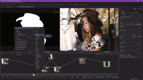
Figure 11-13. Adding a Merge2 compositing tool node to the project
Delete the polygon mask pipes connecting to the blur and drip nodes and connect your Polygon1 mask output to the Merge2 node’s foreground input. Your Niki.png image loader connects to the background input, and the output goes to your blur and drip nodes, as is shown in Figure 11-14. To show only the model over transparency, set the Merge2 compositing operatorto In and the apply mode(also called a blending mode ) to Screen, as shown on the right side of Figure 11-14, highlighted in red. Be sure to experiment with these five operator mode options, in conjunction with the seventeen apply mode options, as that should give you a feel for what these blending algorithms can do, at least visually.
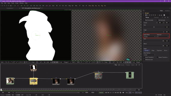
Figure 11-14. Set merge operator to In, and the apply mode to Screen
To make sure that your polygon mask and Niki.png subject matter are synchronizing pixel-for-pixel, select your Polygon1 mask node and select the Image tab and the Output Size Customtab, then enter the resolution for the Niki.png image.
Enter 812 in the Width data field and 577 in the Height data field, as is seen in Figure 11-15. As you can see, you now have the Niki model only, running through an effects processing pipeline, with the polygon-masked subject matter on the transparent checkerboard pattern showing in the same viewport (View2) as the spline control points. The way that this pipeline is set up now will allow you to refine your mask while looking at all of your VFX pipeline processing in real-time, while also seeing the mask result in the left view in the same real-time! Fusion is really cool in how many different ways you can set up a VFX workflow, and all because it uses more advanced nodes, instead of layers.

Figure 11-15. Set Polygon1 mask width and height to match the Niki.png image attributes
Figure 11-16 shows the use of the modify only tool, seen in red, along with the close the polyline, show key points, and show all handlesicons, all toggled on, and therefore in use. Adjust your polygon, and watch your VFX pipeline process in real-time!
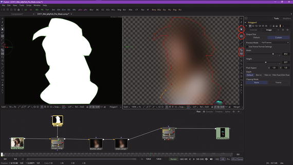
Figure 11-16. Use the modify only tool to modify your pre-mask in real-time
Next, click the Timeline tab, and drag the playhead to 65 to choose a frame that doesn’t have any blur or drip visual effect processing going on. This can be seen in Figure 11-17. You can now further edit your mask polyline. I show a point selected that’s not really needed, just so I can show how to use your delete pointstool, shown circled in red along with the control point I’m deleting (and the time ruler keyframe 65 and the Timeline tab).
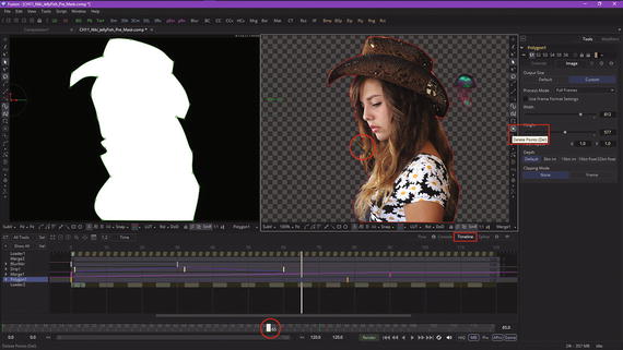
Figure 11-17. Move the playhead to frame 65, and delete unneeded points
Next, let’s take a look at how to animate polyline masks.
Animated Polyline Masking: Keyframing the Mask
Even more advanced VFX pipelines can be created by using animated polylinesto create masking for your visual effect. This method can be used with static imagery, image sequences, vector assets, imported digital video, or any other effect or objective that needs to be masked. Animating polyline masks is done much like an effect node animation is accomplished—by enabling animation and then changing your playhead position, and then adjusting control point position and handles on different frames. Fusion will observe what you are doing and will create your keyframe data.
For the current project, this should amount to selecting the Polygon1 mask node and, in the Control Panel area, clicking on the Controls tab and, at the bottom, right-clicking on shape animation (control), as is shown in Figure 11-18.
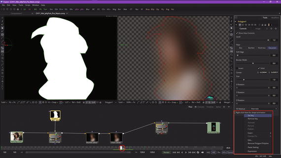
Figure 11-18. Select Polygon1 mask node, and set shape animation control key in the Controls Tab
Select set keyand set your initial keyframe, then enter the timeline editor, as seen in Figure 11-19, and go to frame 70 using the playhead. Pull some polyline control points out at the bottom of the mask. This will show both the result and the mask!

Figure 11-19. Move playhead to 70 and edit some control points
To see the smooth polyline mask animation, simply drag the playhead back and forth between keyframes 65 and 70. It will show your polyline mask “morph” result about halfway between the keyframe range, and, as you can see in Figure 11-20, the result is quite professional! The primary reason Fusion uses polylines for masking rather than using a pixel-based approach is to enable polyline animation, as we are learning here, to be done quickly and professionally.
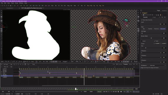
Figure 11-20. Drag the playhead and watch your polyline animate
Next, let’s take a look at mask edge softening controls.
Double Polylines: Blurring the Edges of Your Mask
As you may know from other popular new media software such as GIMP, masking tools can apply a blur function to your mask to soften the edge for the entire mask. Since the blur is applied across the mask, it applies a softening effect equally across all of the edges. However, there will be times when softening isolated parts of the masking polyline while keeping other parts razor sharp will be desirable for the project. Fusion calls the controlled softness non-uniform softness. In Fusion, this is created by converting the polyline shape or segment from single polyline to double polyline. Double polylines are comprised of an inner and outer shape. The inner shape is the original polyline shape. An outer shape can also be added in order to determine the spread area for the softness, so that you can control how any effect ramps in 2D space.
The greater the distance between the outer shape and the inner shape, the softer that edge portion of the shape becomes. To convert the current mask into a double polyline, click the Double Polyline button , seen highlighted in red in Figure 11-21, in both viewports, as we have set up the flow node editor to show the polygon mask in View1 and the merge composite in View2 so that we can see the mask and its result at the same time.
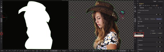
Figure 11-21. Click the make double tool and select a polyline
You can also right-click in each viewer and select make outer polylinein the polyline mask’s context menu. The shape will be converted into a synchronized inner and outer polyline, represented by a red and green dashed spline, as seen in Figure 11-22. As you would expect, both polylines start with the same shape as the original source polyline. This keeps the mask sharp (as its default setting) and, more important, will allow animation that has been applied to a polyline to remain intact. Use the modify only tool to move some outer polyline points, as seen in Figure 11-22, so as to create your double polyline softening .
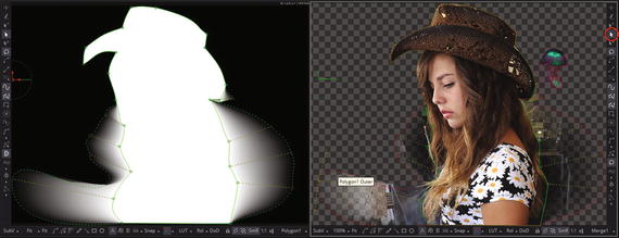
Figure 11-22. Showing Controls and Effect of Double Polyline Mask
If the spline is de-selected, you’ll need to click on it, with the double polyline tool active, in order to show Fusion 8 which polyline you want to double. What is really cool is that in the mask-only View1, you can see the exact amount of blur or softening that is being applied as you work with this tool. Next, drag your playback head and watch your doubled polylines animate! Since you have not keyframed your outer polyline, only your inner polyline animates, thus animating your softening effect, as can be seen in Figure 11-23.

Figure 11-23. Drag your playhead and watch the double polyline animate the soft blur area around the model
As you are starting to realize, there is a considerable amount of work to be done after you set up your VFX pipelines, especially on a keyframe by keyframe (effect and mask tweaking ) basis. We can look at how to set up these tools and how they work in this fundamentals title, but true expertise with Fusion comes from time spent fine-tuning VFX projects until the result is visually perfect, as well as seamless with actual perception of realitystandards present in film, television, and 3D gaming.
Summary
In this eleventh chapter, we took a look at how advanced masking is accomplished in Fusion. We looked at how to create masks, how to animate masks, and how to control edge-softness blending using double polylines. In Chapter 12, you will learn about keying, or chroma keying and luma keying, concepts and techniques.