
In the previous chapter, we prepared the Pi for supercomputing by installing the necessary libraries, frameworks, and tools. In this chapter, we will learn to create a network of multiple Pis and use it to run various commands in parallel.
Making a Backup of the MicroSD card
Once we configure the Pi, update it, and install necessary packages and utilities, we should make a backup of the microSD card. This is necessary because (God forbid!) if the microSD card or the Pi were damaged or lost, then we could resume our work with the backup. It is advised to always have a backup of a microSD card with Raspbian OS installed and updated. Additionally, backing up after installing the necessary packages, tools, and utilities required for the project is also a good idea which I always follow without fail.
To make a backup of the microSD card, first remove it from the Pi and insert it into the SD card reader. Connect the SD card reader to a Windows computer where Win32DiskImager is installed. Open Win32DiskImager and choose a location of your choice. Choose an appropriate name for the backup file. Append the extension .img or .IMG after the filename. The .img or .IMG extension is used for raw storage disk images. See the following (Figure 6-1) screenshot for an example.
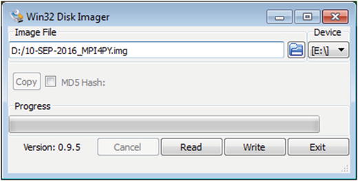
Figure 6-1. Taking the microSD card backup
Then click the Read button. Once finished, it will display the following (Figure 6-2) dialogue box.

Figure 6-2. Backup completed
The image file of the updated version of the Raspbian OS, MPICH, and MPI4PY installation is now saved on the hard drive. We can use this image to prepare other microSD cards for the rest of the nodes of the supercomputer. To do that, we just need to write this image to other microSD cards with Win32DiskImager.
Preparing Nodes of the Supercomputer
Using the OS image which we prepared in the previous section, we will prepare other nodes of the supercomputer. Write this OS image onto other microSD cards using Win32DiskImager. Once all the microSD cards are ready, insert them into Pis. We should have a unique hostname for each Pi. We can change the hostname of a Pi with raspi-config. Go to Advanced Options and select A2 Hostname. Change the hostname as shown in the screenshot below (Figure 6-3).

Figure 6-3. Changing the hostname
Once the hostname is changed, the prompt in lxterminal appears as in the screenshot below (Figure 6-4).

Figure 6-4. The lxterminal prompt after changing the hostname
As you can see, the hostname raspberrypi in the prompt and in the title of the lxterminal window is replaced with pi001.
Follow the same steps for all the Pis and change their hostnames to pi002, pi003, and so on.
Networking the Pis
Now, this is a bit of a tricky part. There are many ways we can network the Pis together. The choice depends upon the infrastructure and the budget available. Let’s explore a few ways to accomplish this without much hassle.
LAN with DHCP
This option works well for managed network switches and WiFi routers. Access the management console of the managed switch or WiFi router. After logging in to the management console, there will be options to set the range of addresses for DHCP. Modify that range as we are going to add more devices to that.
For WiFi routers, the management console is usually a webpage. It can be accessed by connecting to the WiFi and then typing its IP address into a browser. It usually has authentication in the form of a username and a password, which is usually listed in the WiFi router manual. Every WiFi router has ethernet ports for wired LAN as shown below (Figure 6-5).
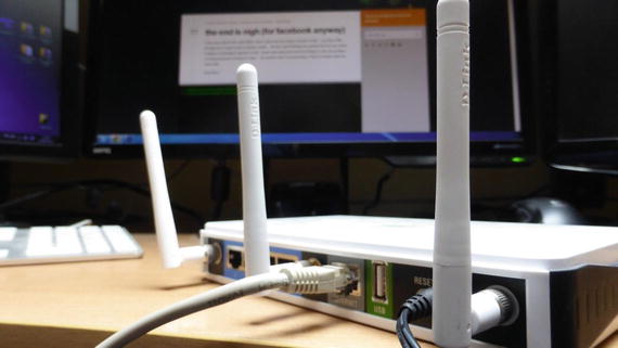
Figure 6-5. Rear side of a WiFi router (image from https://www.flickr.com/photos/smemon/ )
Update the network settings in /etc/network/interfaces for connecting automatically to the LAN and DHCP as an IP address allocation scheme. Following is a sample /etc/network/interfaces file:
source-directory /etc/network/interfaces.dauto loiface lo inet loopbackauto eth0iface eth0 inet dhcp
WiFi Network
We know that all the models of Pi prior to Pi 3 require a USB WiFi adapter. The best option is if you have a WiFi router and many Pi 3s. If the Pis are of earlier models than Pi 3, you will have to invest in buying USB WiFi adapters. After equipping the relevant models of Pi with USB WiFi adapters, update the network settings in /etc/network/interfaces for connecting automatically to the WiFi.
The following is a sample /etc/network/interfaces file.
source-directory /etc/network/interfaces.dauto loiface lo inet loopbackauto wlan0iface wlan0 inet dhcpwpa-ssid "ASHWIN"wpa-psk "internet"
Replace ASHWIN with the ssid of your WiFi network and replace internet with the password of your WiFi network.
LAN with Static IP Addresses
This is my preferred method. All managed network switches and WiFi routers have a range for static IP addresses. Choose a few addresses for the nodes in the cluster and then update the /etc/network/interfaces file. Use the IP address of the managed network switch or WiFi router as the value for the gateway.
Using a low-cost unmanaged network switch is probably the cheapest option. “Unmanaged” means that there is no management console for them. Just connect the Pis to the switch with ethernet cables and update the /etc/network/interfaces as follows:
source-directory /etc/network/interfaces.dauto loiface lo inet loopbackauto eth0iface eth0 inet static# Your static IPaddress 192.168.0.2# Your gateway IPgateway 192.168.0.1netmask 255.255.255.0# Your network address familynetwork 192.168.0.0broadcast 192.168.0.255
For all the Pis, the network settings (except the IP address) will be the same as above. The IP addresses will be unique. Also, as the switch is unmanaged, we are assigning it an IP address manually by using the same value for the gateway (192.168.0.1 in the example above). The value of the gateway must be the same for all the Pis.
Reboot the Pis after changing the network settings.
The following are a few low-cost unmanaged switches and their respective product pages.
Using nmap to Find the IP Addresses of Pis
Regardless of the type of network (ethernet or WiFi) and the IP address allocation scheme (static or dynamic), we will need to know the IP addresses of all the Pis in the network in order to use the network of Pis as a cluster. In the previous chapter, we installed the nmap utilty. We will now use it for finding the IP addresses of the Pis in the network.
Connect a monitor, keyboard, and mouse to pi001. We will use pi001 as the master node. We will use lxterminal in pi001 for running commands and parallel programs for the supercomputer.
Connect all the Pis to the network. We need not connect any display or I/O devices to other Pis.
Boot up all the Pis. Once all the Pis boot up, scan the network with nmap.
The following is the command for scanning the network:
sudo nmap -sn 192.168.0.*In the command above, the first three bytes in 192.168.0.* correspond to the IP address of my network. Replace them with the first three bytes of your network identifier and run the command in lxterminal on pi001.
The output will be as follows:
Starting Nmap 6.47 ( http://nmap.org ) at 2016-09-15 18:02 ISTmass_dns: warning: Unable to determine any DNS servers. Reverse DNS is disabled.Try using --system-dns or specify valid servers with --dns-serversNmap scan report for 192.168.0.2Host is up (0.0020s latency).Nmap scan report for 192.168.0.3Host is up (0.0018s latency).Nmap scan report for 192.168.0.4Host is up (0.0016s latency).Nmap scan report for 192.168.0.5Host is up (0.0014s latency).Nmap done: 256 IP addresses (4 hosts up) scanned in 2.70 seconds
Write down the IP addresses of all the Raspberry Pis in the network. In this case, the IP addresses are 192.168.0.2, 192.168.0.3, 192.168.0.4, and 192.168.0.5.
Running the hostname Command on Multiple Pis with mpirun
On pi001, navigate to /home/pi by running the following command:
cd ∼Create a new file named myhostfile. Add all the IP addresses written down earlier to myhostfile as follows:
192.168.0.2192.168.0.3192.168.0.4192.168.0.5
Now run the following command:
mpirun -hostfile myhostfile -np 4 hostnameIt will show an output with an error and the command hostname will not run on all the hosts listed in the file myhostfile.
This is because we are trying to run a command from pi001 remotely on pi002, pi003, and pi004. We do not have authentication for that.
Exchanging the ssh-keygen Keys for Automatic Authentication
The ssh-keygen utility is used to generate authentication keys. To establish authentication between any two Linux computers, these are the steps:
Generate keys for both the hosts using ssh-keygen.
Exchange the keys between hosts by remotely copying them to each other.
Add the keys to the list of authorized hosts.
Once this is done, we can do the following actions without a password, since after the key exchange the password will not be prompted for again.
Log in to the remote host.
Execute a shell command on the remote host.
We can also use the ssh command in a shell script to automate the tasks in a remote host. We are using pi001 as the master node, so we want to remotely run the commands from pi001 on other nodes and vice-versa. I have set up a cluster of four nodes, so the pairs of hosts for the key exchange are (pi001,pi002), (pi001,pi003), and (pi001,pi004).
Let’s exchange the keys. Open lxterminal and go to the home directory of pi001.
cd ∼Run the ssh-keygen command to generate the key. Just press the Enter key every time it prompts for any input. The following is the output on lxterminal:
Generating public/private rsa key pair.Enter file in which to save the key (/home/pi/.ssh/id_rsa):Enter passphrase (empty for no passphrase):Enter same passphrase again:Your identification has been saved in /home/pi/.ssh/id_rsa.Your public key has been saved in /home/pi/.ssh/id_rsa.pub.The key fingerprint is:03:bc:3f:5a:28:88:b7:ac:6c:50:f0:81:5e:f9:6d:5f pi@pi001The key's randomart image is:+---[RSA 2048]----+| . . ||o .o . ||.o... + || .o . = E || . o S . ||.. . o o ||o o . . + ||.+ . . o . ||ooo . |+-----------------+
Note that the image displayed on the command prompt will be different every time as the key generated for each execution is different.
The above execution creates a hidden directory .ssh in the home directory of the Pi. Go to the .ssh directory.
cd .sshCheck the contents of the .ssh directory by running the ls command as follows:
pi@pi001:∼/.ssh $ lsid_rsa id_rsa.pub
In the output above, id_rsa is the private key and id_rsa.pub is the public key for the host pi001. We have to copy the public key to the hosts where we want to remotely login and execute commands.
To keep things organized, we copy the public key id_rsa.pub to a new file, pi01.
cp id_rsa.pub pi01We need to add the contents of this pi01 file to the authorized_keys file of other hosts to enable remote access without authentication.
Now log in to pi002 with the following command:
ssh [email protected]We will be prompted for the password of pi002. Enter the password.
Like we did on pi001, run the following commands on pi002 to generate the public key:
ssh-keygencd .sshcp id_rsa.pub pi02
Now we need to copy the public key file of pi001 to pi002 using scp.
scp 192.168.0.2:/home/pi/.ssh/pi01 .Add the contents of pi01 to authorized_keys by running the following command:
cat pi01>>authorized_keysFinally, log out from pi002 using the logout commands.
For pi003, we have to follow the same steps again.
Login to pi003.
ssh [email protected]Run the following sequence of commands on pi003:
ssh-keygencd .sshcp id_rsa.pub pi03scp 192.168.0.2:/home/pi/.ssh/pi01 .cat pi01>>authorized_keyslogout
For pi004, we have to follow the same steps again.
Login to pi004.
ssh [email protected]Run the following sequence of commands on pi004:
ssh-keygencd .sshcp id_rsa.pub pi04scp 192.168.0.2:/home/pi/.ssh/pi01 .cat pi01>>authorized_keyslogout
In pi001 run the following sequence of commands to copy the public keys of pi002, pi003, and pi004 to pi001.
cd /home/pi/.sshscp 192.168.0.3:/home/pi/.ssh/pi02 .scp 192.168.0.4:/home/pi/.ssh/pi03 .scp 192.168.0.5:/home/pi/.ssh/pi04 .
Then run the following commands to add these public keys to the list of authorized keys of pi001:
cat pi02>>authorized_keyscat pi03>>authorized_keyscat pi04>>authorized_keys
This completes the setup of the cluster. To test the setup, run the following command on pi001:
mpirun -hostfile myhostfile -np 4 hostnameThe output of the command above should be as follows:
pi001pi002pi003pi004
Congrats! We have built our own mini-supercomputer cluster. In the next section, we will learn how to organize our cluster in a nice-looking stack.
Organizing the Pis in the Cluster
When I built my first cluster , I thought of creating a custom acrylic case; however, the estimated cost exceeded my budget. I also thought of creating a custom case for the cluster by 3D printing, but the 3D printing contractor also quoted an astronomical sum for this. So I decided to try out a more cost-effective way to organize the Pis in the cluster. I used M3 Hex standoff spacers for creating a stack of Pis. We need two types of standoffs for this, male-to-female and female-to-female. We will use these to create a stack now. It is essential that the length of the standoffs must be at least 25mm to avoid the contact of Raspberry Pi PCBs to each other altogether.
Note
Search for M3 Hex standoff spacers on Google.
Take four male-to-female standoffs and attach them to a Pi as shown in the image (Figure 6-6) below.
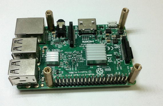
Figure 6-6. Attaching male-to-male standoffs to the Pi
After that, take four female-to-female standoffs and attach them to the bottom of the Pi as shown in the image (Figure 6-7) below.
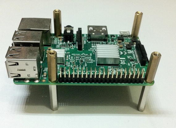
Figure 6-7. Attaching female-to-female standoffs to the cluster base
Now attach the second Pi to this as shown (Figure 6-8) below.
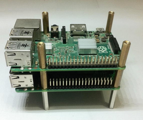
Figure 6-8. Adding second Pi to the stack
Finally, after adding the remaining two Pis to this, the cluster stack looks like the picture below (Figure 6-9).
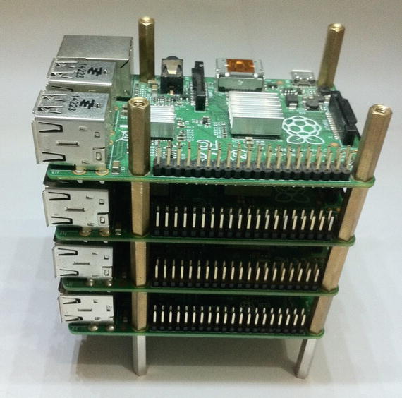
Figure 6-9. Raspberry Pi Supercomputer stack
Conclusion
In this chapter, we learned how to connect several Pis together to build an ultra-low-cost mini-supercomputer cluster. We also learned how to organize the cluster in a convenient stack. In the next chapter, we will learn how to overclock the various models of Pi to increase the computational power of the Pis in the cluster at no additional cost.