
The Raspberry Pi has a UART interface to allow it to perform serial data communication. The data lines used are 3.3 V logic-level signals and should not be connected to TTL logic (+5 V) (they also are not RS-232 compatible). To communicate with equipment using RS-232, you will need a converter module.
RS-232 Converter
While an industrious person could build their own RS-232 converter, there is little need to do so when cheap converters on a pcb are available.
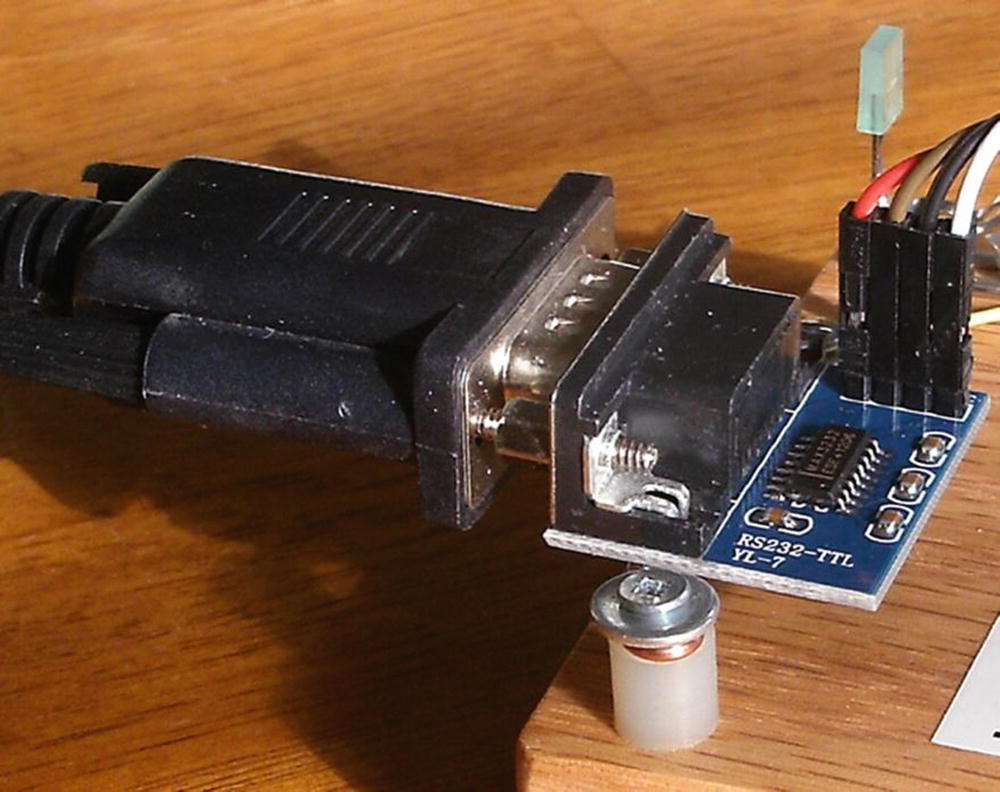
MAX232CSE interface
I also recommended that you choose a unit supporting the hardware flow control signals. Look for the CTS and DTR signals. A full RS-232 converter would also include DTR, DSR, and CD signals.
Note
Throughout this text, we’ll refer to 3 V, knowing that it is more precisely 3.3 V.
TTL Adapters
You can also use TTL adapters instead of converting the signal to the +/- voltages required by RS-232. The Pi requirement is that the signaling side (TTL) should be capable of operating at +3.3 V instead of the usual +5 V. Using a +5 V adapter could damage your Pi. Units that can interface +3.3 V will likely have a jumper to select the voltage.
DTE or DCE
DCE: Data communications equipment (female connector)
DTE: Data terminal equipment (male connector)
A normal USB serial adapter (for a laptop, for example) will present a DTE (male) connector. The wiring of this cable is such that it expects to plug into to a DCE (female) connection. When this holds true for your Raspberry Pi’s adapter, the laptop’s serial adapter can plug straight into the DCE (female) connector, eliminating the need for a crossover cable or null modem.
Consequently, for your Pi, choose a RS-232 converter that provides a female (DCE) connector. Likewise, make sure that you acquire for the laptop/desktop a cable or USB device that presents a male (DTE) connection. Connecting DTE to DTE or DCE to DCE requires a crossover cable, and depending on the cable, a “gender mender” as well. It is best to get things “straight” right from the start.
Assuming that you used a DCE converter for the Pi, connect the RS-232 converter’s 3 V logic TX to the Pi’s TXD0 and the RX to the Pi’s RXD0 data lines.
All this business about DCE and DTR has always been rather confusing. If you also find this confusing, there is another practical way to look at it. Start with the connectors and the cable(s) that you plan to use. Make sure they mate at both ends and that the serial cable is known to be a straight cable (vs. a crossover). Once those physical problems are taken care of, you can get the wiring correct. Connect the TX to RX, and RX to TX. In other words, you wire the crossover in your own wiring between the RS-232 adapter and the Raspberry Pi. The important thing to remember is that somewhere the transmitting side needs to send a signal into the RX (receiving) side, in both directions.
Note
A straight serial cable will connect pin 2 to pin 2, and pin 3 to pin 3 on a DB9 or DB25 cable. A crossover cable will cross these two, among other signal wires.
RS-232
RS-232 is the traditional name for a series of standards related to serial communication. It was first introduced by the Radio Sector of the EIA in 1962. The first data terminals were teletypewriters (DTE) communicating with modems (DCE). Early serial communications were plagued by incompatibilities until later standards evolved.
A serial link includes two data lines, with data being transmitted from a terminal and received by the same terminal. In addition to these data lines are several handshaking signals (such as RTS and CTS). By default, these are not provided for by the Raspberry Pi.
Serial signal
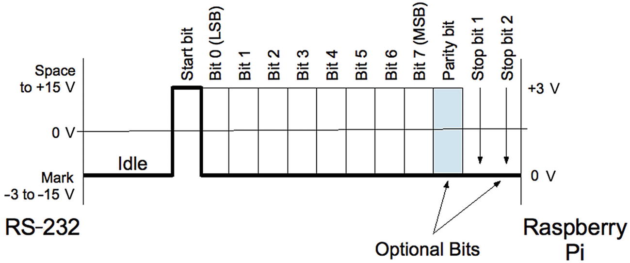
The standard states that the signal is considered to be in a mark state, when the voltage is between –3 and –15 V. The signal is considered in a space state if the voltage is between +3 and +15 V. The RS-232 data line is in the mark state when the line is idle.
Start Bit
When an asynchronous character of data is to be sent, the line first shifts to a space level for the duration of 1 bit. This is known as the start bit (0). Data bits immediately follow.
Asynchronous lines do not use a clock signal like synchronous links. The asynchronous receiver must have a clock matching the same baud rate as the transmitter. The receiver samples the line 16 times in the bit cell time to determine its value. Sampling helps to avoid a noise pulse from triggering a false data read.
Data Bits
Data bits immediately follow the start bit, with the least significant bit first. A space is a 0 data bit, while mark represents a 1 bit. Early teletype equipment used 5 data bits sending characters in the 5-bit Baudot code.11 For this reason, serial ports can be configured for 5, 6, 7, or 8 data bits. Before the ASCII character set was extended to 8 bits, it was common to use 7-bit serial data.
Parity Bit
An optional parity bit can be generated when transmitting or can be detected on the receiving side. The parity can be odd, even, or stick (mark or space). The most commonly used setting today is No Parity, which saves 1-bit time for faster communication. Older equipment often used parity to guard against errors from noisy serial lines. Odd parity is preferred over even because it forces at least one signal transition in the byte’s transmission. This helps with the data reliability.
RS-232 Parity Settings
Parity | X | Notes |
|---|---|---|
None | N | No parity bit |
Even | E | 1 if even number of data 1-bits |
Odd | O | 1 if odd number of data 1-bits |
Mark | M | Always at mark level (1) |
Space | S | Always at space level (0) |
Stop Bits
Asynchronous communication requires synchronizing the receiver with the transmitter. For this reason, 1 or more stop bits exist so that the receiver can synchronize with the leading edge of the next start bit. In effect, each stop bit followed by a start bit provides built-in synchronization.
Stop-Bit Configuration
Stop Bits | Description |
|---|---|
1 | 1 stop bit |
1.5 | 1.5 stop bits (†) |
2 | 2 stop bits |
†Unsupported by the Raspberry Pi
Baud Rate

where
B is the baud rate.
s is the start bit (always 1 bit).
d is the number of data bits (5, 6, 7, or 8).
p is the parity bit (0 or 1).
S is the stop bit (1, 1.5, or 2).

The addition of a parity bit reduces the transmission rate to 10,472.7 bytes per second.
Standard Baud Rates
Rate | Notes |
|---|---|
75 | Teletypewriters |
110 | Teletypewriters |
300 | Low-speed (acoustic) modem |
1200 | |
2400 | |
4800 | |
9600 | |
19200 | |
38400 | |
57600 | |
115200 | Raspberry Pi console |
Break
With asynchronous communication, it is also possible to send and receive a break signal. This is done by stretching the start bit beyond the data bits and the stop bit(s), and eventually returning the line to the mark state. When the receiver sees a space instead of a mark for the stop bit, it sees a framing error.
Some UARTs distinguish between a framing error and a break by noting how long the line remains in the space state. A simple framing error can happen as part of noisy serial line communications (particularly when modems were used) and normally attributed to a received character error. Without break detection, it is possible to assume that a break has been received when several framing errors occur in a sequence. Short sequences of framing errors, however, can also just indicate a mismatch in baud rates between the two endpoints.
Flow Control
Any link that transmits from one side to a receiver on the other end has the problem of flow control. Imagine a factory assembly line where parts to be assembled arrive at the worker’s station faster than he/she can assemble them. At some point, the conveyor belt must be temporarily stopped, or some parts will not get assembled. Alternatively, if the conveyor belt is reduced in speed, the assembly worker will be able to keep up, but at a slower than optimal pace.
Unless the serial link receiver can process every character of data as fast as it arrives, it will need flow control. The simplest approach is to simply reduce the baud rate, so that the receiver will always keep up. But this isn’t always satisfactory. A logging application might be able to write the information quickly, except when writes occur to an SD card, for example.
Data transmitted to the terminal (DTE)
Data transmitted to the data communications equipment (DCE)
Hardware flow control
Software flow control
Hardware Flow Control
Hardware Flow Controls
DTE | Direction | DCE | Description | Active |
|---|---|---|---|---|
RTS | → | RTS | Request to send(†) | Low |
CTS | ← | CTS | Clear to send(†) | |
DSR | ← | DSR | Data set ready | Low |
DTR | → | DTR | Data terminal ready |
† Primary flow control signals
The most important signals are the ones marked with a dagger in Table 10-4. When CTS is active (mark), for example, the DCE (Pi) is indicating that it is OK to send data. If the DCE gets overwhelmed by the volume of data, the CTS signal will change to the inactive (space) state. Upon seeing this, the DTE (desktop) is required to stop sending data. Otherwise, loss of data may occur.
Similarly, the desktop operating as the DTE is receiving data from the DCE (Pi). If the laptop gets overwhelmed with the volume of incoming data, the RTS signal is changed to the inactive state (space). The remote end (DCE) is then expected to cease transmitting. When the desktop has caught up, it will reassert RTS, giving the DCE permission to resume.
The DTR and DSR signals are intended to convey the readiness of the equipment at each end. If the terminal was deemed not ready (DTR), DSR is not made active by the DCE. Similarly, the terminal will not assert DTR unless it is ready. In modern serial links, DTR and DSR are often assumed to be true, leaving only CTS and RTS to handle flow control.
Where flow control is required, hardware flow control is considered more reliable than software flow control.
Software Flow Control
To simplify the cabling and the supporting hardware for serial communications, the hardware flow controls can be omitted/ignored. In its place, a data protocol is used instead.
Software Flow Control Characters
Code | Meaning | ASCII | Hex | Keyboard |
|---|---|---|---|---|
XOFF | Pause transmission | DC3 | 13 | Control-S |
XON | Resume transmission | DC1 | 11 | Control-Q |
In a terminal session, the keyboard commands can be used to control the serial connection. For example, if information is displaying too fast, the user can type Ctrl-S to cause the transmission to stop. Pressing Ctrl-Q allows it to resume.
- 1.
Line noise can prevent the receiver from seeing the XOFF character and can lead to loss of data (due to data overrun).
- 2.
Line noise can prevent the remote end from seeing the XON character and can fail to resume transmission (causing a link “lockup”).
- 3.
Line noise can cause a false XON/XOFF character to be received (data loss or link lockup).
- 4.
The delay in the remote end seeing a transmitted XOFF character can cause loss of data if the receiving buffer is full.
- 5.
The XON and XOFF characters cannot be used for data in the transmission link.
Problems 1 to 3 can cause link lockups or data loss. Problem 4 is avoidable if the buffer notifies the other end early enough to prevent overflow. Problem 5 is an issue for binary data transmission.
Raspberry Pi UARTs
UART | Hardware | Node | GPIO | ALT |
|---|---|---|---|---|
UART0 | PL011 | /dev/ttyAMA0 | 14 & 15 | 0 |
UART1 | Mini UART | /dev/ttyS0 | 14 & 15 | 5 |
Whether the PL011 or the mini UART is used depends upon the model of the Raspberry Pi. Originally, this question was simple to answer. The Model B and Model A Pi’s simply used the PL011 (/dev/ttyAMA0) device for the console. The mini UART (/dev/ttyS0) is a different hardware block and was also available, albeit with limited features.
With the addition of Wireless and Bluetooth on the Pi 3 and the Pi Zero W, the PL011 UART was commandeered for the BT (Bluetooth) and WIFI support while the mini UART was substituted for the serial console. All other models use the preferred PL011 device for the console instead.
However, the rules for what is assigned is more complicated now that the device tree overlays are being used. More detail is available from raspberrypi.org. The following online document, which doesn't include a date-stamp, has more of the gory details:
https://www.raspberrypi.org/documentation/configuration/uart.md
Which Is in Use?
So this Pi is configured to use the mini UART (/dev/ttyS0).
If cmdline.txt uses the alias serial0 to refer to the user-accessible port, the firmware will replace it with the appropriate port whether or not this overlay is used.
Disabling the Serial Console
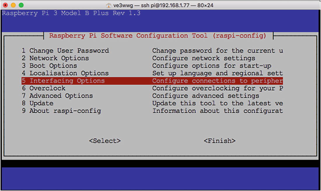
The opening dialog for raspi-config, with “Interface Options” selected
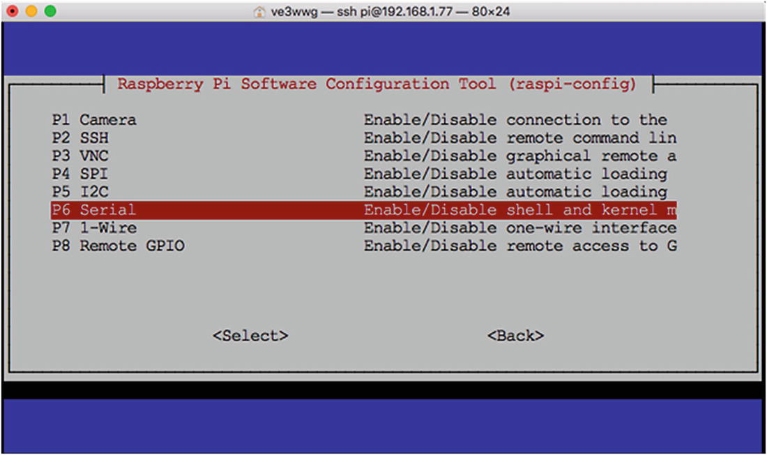
Select “Serial” in raspi-config and press Return
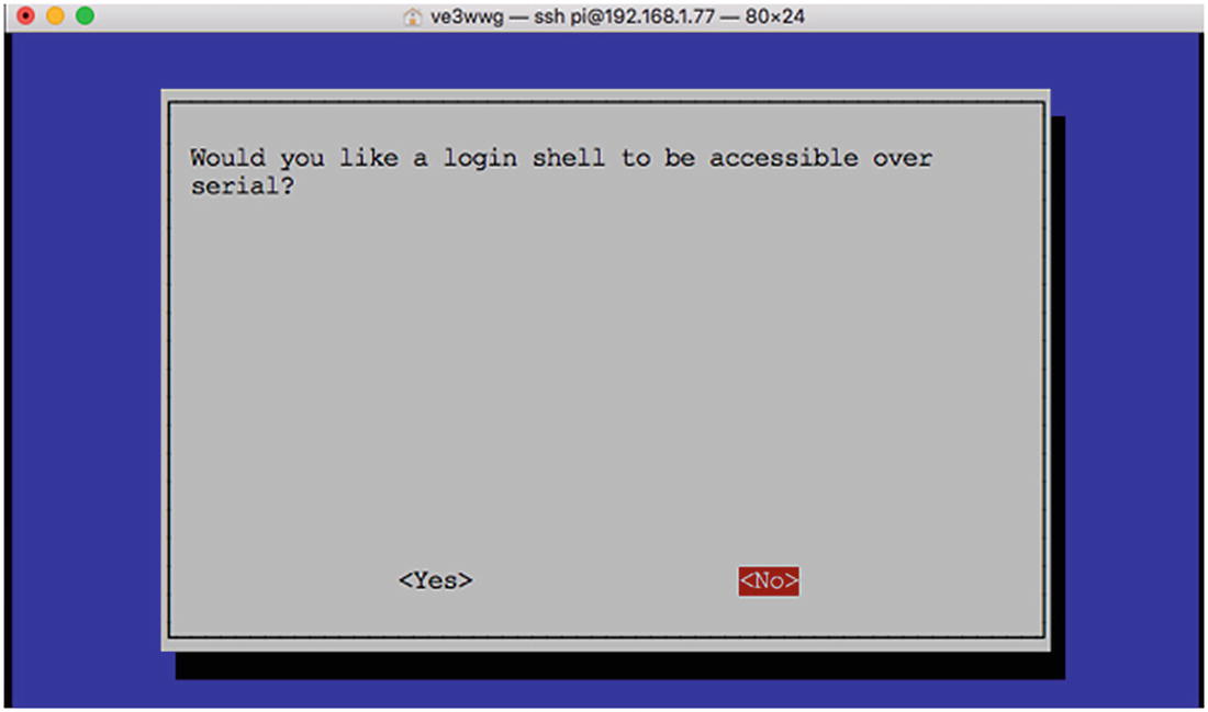
Choose “<No>” to disable the console in raspi-config
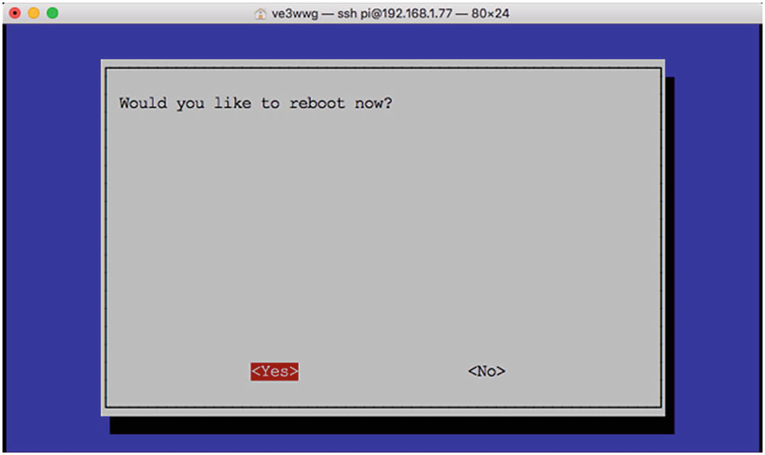
The raspi-config dialog ends by asking if you want to reboot
Raspberry Pi 3 Serial Console
Note the “ttyS0” above the prompt. Despite the fact that /dev/serial0 does not exist (on the B+), Raspbian arranges that /dev/ttyS0 (mini UART) is used as the console.
Raspberry Zero Serial Console
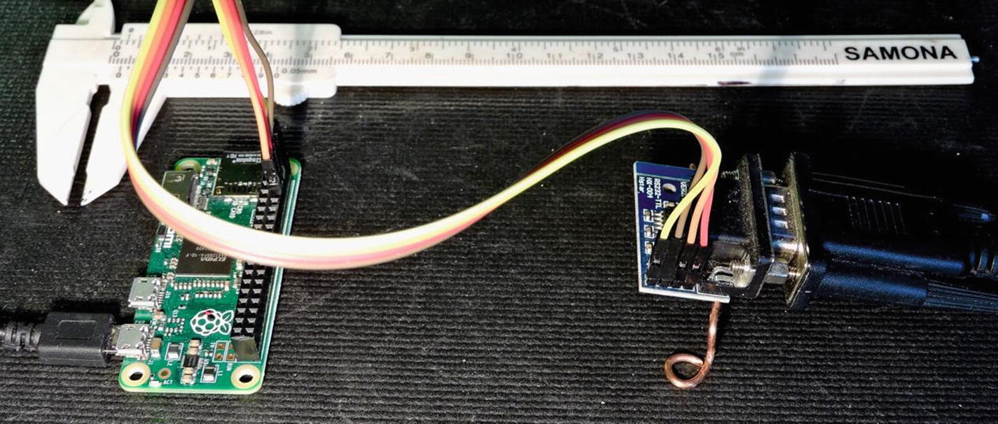
Raspberry Pi Zero with serial console wired to RS232C adapter. The adapter has a true RS232C to USB plugged into it.
P1-01 (+3.3 V) to VCC
P1-06 to Gnd
P1-08 (GPIO14) to TX
P1-10 (GPIO15) to RX
With this arrangement, there is no flow control. Given the high baud rate involved, if improved data integrity is needed, drop the baud rate to something lower like 9600 baud.
PL011 and Mini UART Differences
The mini UART has smaller FIFOs and does not support hardware flow control. Without flow control, it will be prone to losing data at high data rates. The mini’s baud rate is also linked to the VPU clock, leading to other problems.
No break detection
No framing error detection
No parity bit support
No receive timeout interrupt
No DCD, DSR, DTR, or RI signals
The Linux console can be re-enabled by adding enable_uart=1 to config.txt. This also fixes the core_freq to 250Mhz (unless force_turbo is set, when it will fixe to 400Mhz), which means that the UART baud rate stays consistent.
Avoid the mini UART if you can.
PL011 UART Features
No Infrared Data Association (IrDA) support
No Serial InfraRed (SIR) protocol encoder/decoder (endec)
No direct memory access (DMA)
No support for signals DCD, DSR, DTR, and RI
Separate 16×8 transmit and 16×12 receive FIFO buffers
Programmable baud rate generator
False start-bit detection
Line-break generation and detection
Support of control functions CTS and RTS
Programmable hardware flow control
- Fully programmable serial interface characteristics:
Data can be 5, 6, 7, or 8 bits.
Even, odd, mark, space, or no-parity bit generation and detection.
1 or 2 stop-bit generation.
Baud rate generation, DC up to UARTCLK/16.
Receive FIFO trigger levels are 1/8, 1/4, 1/2, 3/4, and 7/8.
Transmit FIFO trigger levels are 1/8, 1/4, 1/2, 3/4, and 7/8.
The internal register map address space and the bit function of each register differ.
1.5 stop bits is not supported.
No independent receive clock.
The only real concern to the application developer is that the 1.5 stop-bits configuration option is not available, which is rarely used these days.
UART GPIO Pins
UART Pins
Function | GPIO | P1/P5 | ALT | Direction | Description |
|---|---|---|---|---|---|
TXD | 14 | P1-08 | 0 | Out | DTE transmitted data |
RXD | 15 | P1-10 | 0 | In | DTE received data |
RTS | 17 | P1-11 | 5 | Out | Request to send |
CTS | 30 | P1-36 | 5 | In | Clear to send |
RTS/CTS Access
Hardware flow controls CTS and RTS are available on GPIO 30 (P1-26) and 17 (P1-11), respectively, when configured. By default these are GPIO inputs, but this can be reconfigured. To gain access to the UART’s CTS and RTS signals, configure GPIO 30 and 17 to alternate function 5.
Summary
As the Raspberry Pi has matured into new models, the features associated with the serial device have become more complicated. Yet the Raspberry Pi Foundation has provided you with the raspi-config tool to simplify the configuration of the serial console or exclusive use serial line.
Armed with the information presented, you will be able to log into your headless Raspberry Pi Zero using the serial adapter. This information puts you in the best possible position to make use of this valuable resource.