
The I2C bus, also known as the two-wire interface (TWI), was developed by Philips circa 1982 to allow communication with lower-speed peripherals.17 It was also economical because it only required two wires (excluding ground and power). Since then, other standards have been devised, building upon this framework, such as the SMBus. However, the original I2C bus remains popular as a simple, cost-effective way to connect peripherals.
I2C Overview
I2C Bus Connections
Connection | GPIO | Description |
|---|---|---|
P1-03 | GPIO-2 | SDA1 (serial bus data) |
P1-05 | GPIO-3 | SCL1 (serial bus clock) |
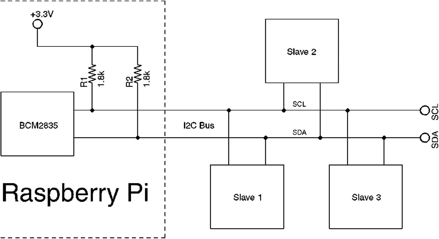
The I2C bus on the Raspberry Pi
SDA and SCL
Both masters and slaves take turns at “grabbing the bus” at various times. Master and slave use open-drain transistors to drive the bus lines. It is because all participants are using open-drain drivers that pull-up resistors must be used (provided by the Pi). Otherwise, the data and clock lines would float between handoffs.
The open-drain driver design allows all participants to drive the bus lines—just not at the same time. Slaves, for example, turn off their line drivers, allowing the master to drive the signal lines. The slaves just listen, until the master calls them by address. When the slave is required to answer, the slave will then assert its driver, grabbing the line. It is assumed by the slave that the master has already released the bus at this point. When the slave completes its own transmission, it releases the bus, allowing the master to resume.
The idle state for both lines is high. The high state for the Raspberry Pi is +3.3 V. Other systems may use +5 V signaling. When shopping for I2C peripherals, choose ones that will operate at the 3.3 V level. Sometimes 5 V peripherals can be used with careful signal planning or using adapters.
Bus Signaling
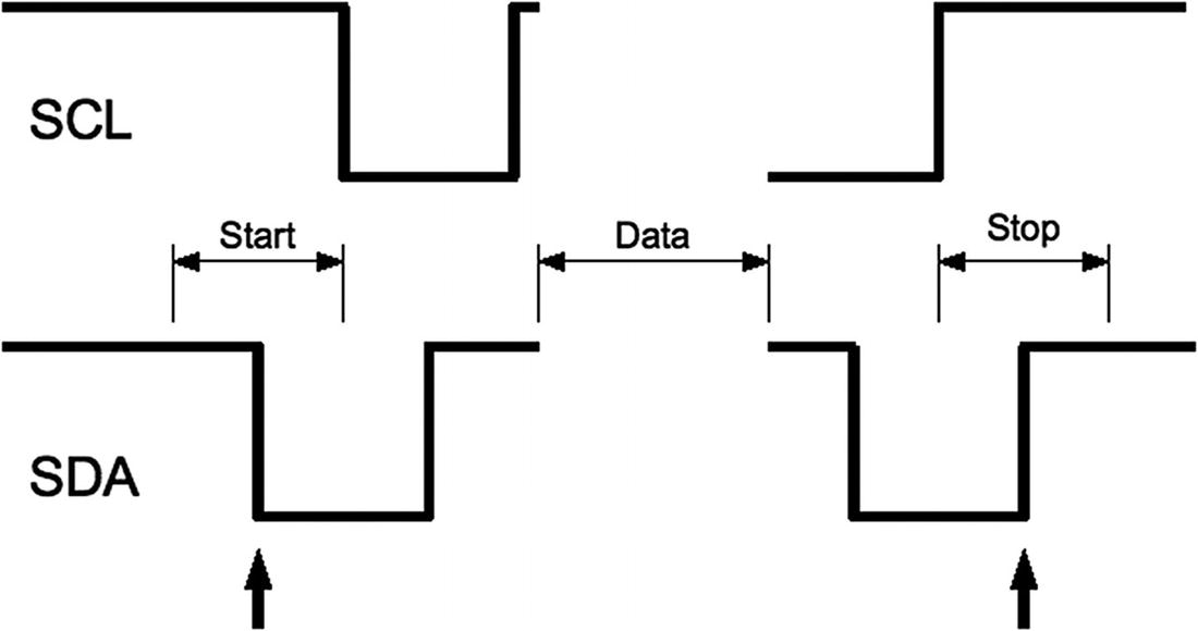
I2C start/stop signaling
The stop bit is also special in that it allows slave devices to know whether more information is coming. When the SDA line transitions from low to high midway through a bit cell, it is interpreted as a stop bit. The stop bit signals the end of the message.
There is also the concept of a repeated start, often labeled in diagrams as SR. This signal is electrically identical to the start bit, except that it occurs within a message in place of a stop bit. This signals to the peripheral that more data is being sent or required as part of another message.
Data Bits
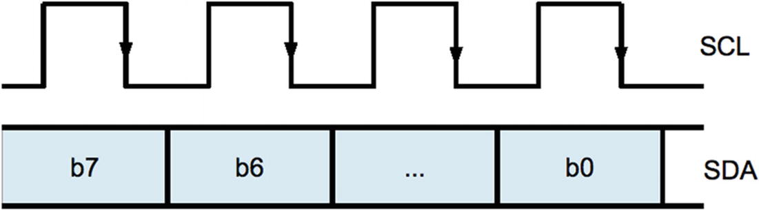
I2C Data bit transmission
Message Formats
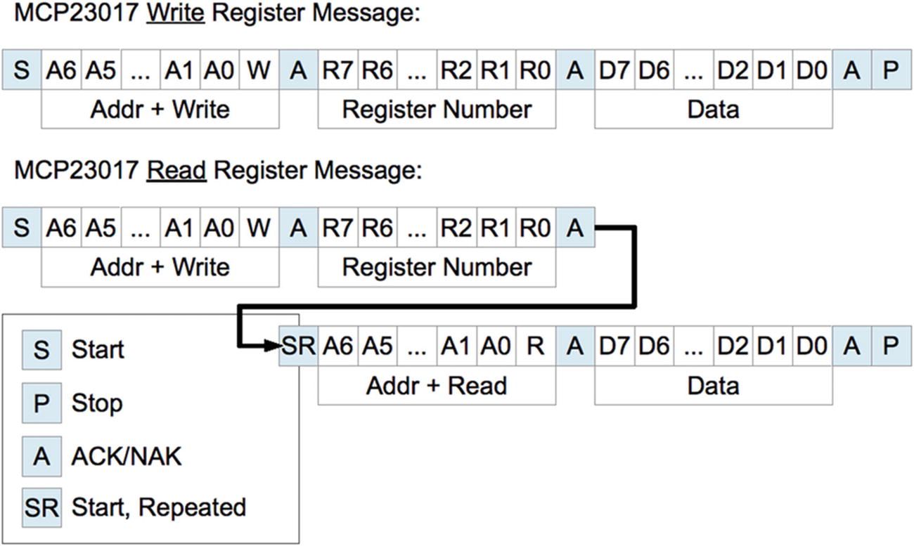
Example I2C messages
The diagram shows each message starting with the S (start) bit and ending with a P (stop) bit. After the start bit, each message begins with a byte containing the 7-bit peripheral address and a read/write bit. Every peripheral must read this byte in order to determine whether the message is addressed to it.
The addressed peripheral is expected to return an ACK/NAK bit after the address is sent. If the peripheral fails to respond for any reason, the line will go high due to the pull-up resistor, indicating a NAK. The master, upon seeing a NAK, will send a stop bit and terminate the transmission.
When the addressed peripheral ACKs the address byte, the master then continues to write when the request is a write. The first example shows the MCP23017 8-bit register number being written next. This indicates which of the peripheral’s registers is to be written to. The peripheral will then ACK the register number, allowing the master to follow with the data byte to be written, into the selected register. This too must be ACKed. If the master has no more data to send, the P (stop) bit is sent to end the transmission.
The second example in Figure 15-4 shows how a message may be composed of both write and read messages. The initial sequence looks like the write, but this only writes a register number into the peripheral. Once the register number is ACKed, the master then sends an SR (start, repeated) bit. This tells the peripheral that no more write data is arriving and to expect a peripheral address to follow. Since the address transmitted specifies the same peripheral, the same peripheral responds with an ACK. This request is a read, so the peripheral continues to respond with 8 bits of the requested read data, with the master ACKing. The master terminates the message with a P (stop) to indicate that no more data is to be read.
Many peripherals will support an auto-increment register mode. This is a feature of the peripheral, however. Not all devices support this. Once a peripheral’s register has been established by a write, successive reads or writes can occur in auto-increment mode, with the register being incremented with each byte transferred. This results in efficient transfers.
I2C Bus Speed
Unlike the SPI bus, the I2C bus operates at a fixed speed within Raspbian Linux. The SoC document claims I2C operation up to 400 kHz, but the default is 100 kHz.
The xxd command reports a group of 4 bytes (-g4) as 00061a80.
The gdb command is used to print (p command) this value in decimal (don’t forget to prefix the reported number with 0x to indicate the value is hexadecimal).
I2C Tools
i2cdetect: Detects peripherals on the I2C line
i2cdump: Dumps values from an I2C peripheral
i2cset: Sets I2C registers and values
i2cget: Gets I2C registers and values
Each of these utilities has a man page available for additional information.
MCP23017
The MCP23S17 is the I2C chip that provides 16 expansion GPIO ports. At startup, the pins default to inputs, but can be configured as outputs like the native Pi GPIO ports. The MCP23S17 is the companion chip for SPI bus.
The chip allows eight different I2C addresses to be wire configured. Like the native Pi GPIOs, the ports can be configured active high or low. The chip operates from a supply voltage of 1.8 to 5.5 V, making it perfect for Pi 3.3 V operation.
The output mode GPIO can sink up to 8 mA of current and source 3 mA. This should be taken into account when driving loads, even LEDs.
For input GPIOs, it has an interrupt capability, signaling an input change on the INTA (GPIOA0 to GPIOA7) or INTB pins (GPIOB0 to GPIOB7). The chip can be configured to report all changes on INTA, which is the way it will be used here. This is important for inputs because otherwise you would need to continuously poll the device.
Perhaps the best part of all is that a kernel driver is available for it. This makes it very convenient to use.
Driver Setup
Optional parameter gpiopin=4 specifies that GPIO4 will be used for sensing interrupts in the chip. GPIO4 is the default.
Optional parameter addr=0x20 specifies the I2C address for the MCP23017 chip. 0x20 is the default.
After the Pi boots back up, log in and check for suspicious error messages using the dmesg command. You can skip that if you’re feeling lucky.
Scrutinize the dmesg log for errors.
Check the configuration and wiring.
Make sure that the MCP23017 chip’s
 pin is wired to +3.3 V.
Wiring
Supply the MCP23017 chip from +3.3 V (not 5 V).
No resistors are required for the bus since the Raspberry Pi already provides R1 and R2.
Important! Wire the
 line to +3.3 V. Otherwise random or complete failure will occur.
Wiring the INTA line is not required if you only plan to use output mode GPIOs. However, the driver will consume the configured GPIO, whether used or not.
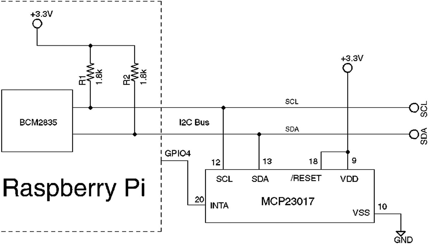
Wiring for the MCP23017 to the Raspberry Pi
When the  line is not wired to +3.3 V, the input to the chip will float. Sometimes the CMOS input will float high and sometimes low (causing a chip reset). I ran into this when I initially wired up the circuit. The worst part was that the driver and chip worked for a while but later developed problems.
The purpose of the INTA line (and GPIO4 in Figure 15-5) is to notify the Pi that an input GPIO port has changed state. This informs the mcp23017 driver to send an I2C request to read the inputs. Without this notification, the driver would have to busy the I2C bus with repeated read requests to see if there is new input.
Testing GPIO Output
With the circuit wired up and the configuration set and the system rebooted, you should see the driver report its presence in /sys/class/gpio as gpiochip496, if you used the I2C address of 0x20.
- 1.
gpiochip496/base lists the starting GPIO number for this device (496).
- 2.
gpiochip496/ngpio lists how many GPIOs are supported (16).
GPIO Associations for Gpiochip496 (I2C Address 0x20)
GPIO | Pin | MCP23017 | GPIO | Pin | MCP23017 |
|---|---|---|---|---|---|
GPIO496 | 21 | A0 | GPIO504 | 1 | B0 |
GPIO497 | 22 | A1 | GPIO505 | 2 | B1 |
GPIO498 | 23 | A2 | GPIO506 | 3 | B2 |
GPIO499 | 24 | A3 | GPIO507 | 4 | B3 |
GPIO500 | 25 | A4 | GPIO508 | 5 | B4 |
GPIO501 | 26 | A5 | GPIO509 | 6 | B5 |
GPIO502 | 27 | A6 | GPIO510 | 7 | B6 |
GPIO503 | 28 | A7 | GPIO511 | 8 | B7 |
After the above, GPIO A7 should now go low.
Testing GPIO Input
As expected, as we changed A7, the input A6 followed.
Test GPIO Input Interrupt
Being able to read a GPIO alone is often not enough. We need to know when it has changed so that it can be read at that point in time. In Figure 15-5, the MCP23017 chip has its INTA pin wired to the Pi’s GPIO4. The MCP23017 will activate that line whenever an unread change in inputs occurs, alerting the driver in the Pi. Only then does the driver need to read the chip’s current input status.
Indeed, this confirms that the interrupt facility works. Note that we monitored GPIO502 (A6) rather than GPIO4. Only the driver needs to monitor GPIO4.
Limitations
The extended GPIOs are not as fast as the native Pi GPIOs.
You may need to do some homework to add more than one MCP23017 chip. While the bus supports up to eight uniquely addressed MCP23017 chips, the device driver might not. It may be possible with added nodes to the device tree.
I/O performance is directly related to the I2C clock rate.
The GPIOs are accessed through the sysfs pseudo file system, further impacting performance.
The main thing to keep in mind is that all GPIO interaction occurs over the I2C bus at the clock rate (100 kHz or 400 kHz). Each I/O may require several bytes of transfer because the MCP23017 has a large set of registers. Each byte transferred requires time. At the default of 100 kHz, a one-byte transfer takes:

To read one GPIO input register requires a start bit, three bytes of data, and a stop bit. This results in a minimum transaction time of 260 μs. That limits the number of GPIO reads to approximately 3,800 reads/s. This doesn’t account for sharing the bus with other devices.
In the end, the suitability depends upon the application. By shifting the highest rate GPIO transactions to the Pi’s native GPIOs and the slower I/Os to the extension GPIOs, you might find that the arrangement works well enough .
I2C API
The bare-metal C language API for the I2C bus transactions will be introduced in this section. Using this API you can program your own interface with another GPIO expander such as the PCF8574, for example. That chip provides eight additional GPIOs but is economical and +3.3 V friendly. It has only one configuration register making it easy to use directly.
Kernel Module Support
Header Files
open(2)
pathname is the name of the file/directory/driver that you need to open/create.
flags is the list of optional flags (use O_RDWR for reading and writing).
mode is the permission bits to create a file (omit argument, or supply zero when not creating).
returns -1 (error code in errno) or open file descriptor >=0.
Error | Description |
|---|---|
EACCES | Access to the file is not allowed. |
EFAULT | The pathname points outside your accessible address space. |
EMFILE | The process already has the maximum number of files open. |
ENFILE | The system limit on the total number of open files has been reached. |
ENOMEM | Insufficient kernel memory was available. |
Note that the device node (/dev/i2c-1) is owned by root, so you’ll need elevated privileges to open it or have your program use setuid(2).
ioctl(2,I2C_FUNC)
I2C_FUNC Bits
Bit Mask | Description |
|---|---|
I2C_FUNC_I2C | Plain I2C is supported (non SMBus) |
I2C_FUNC_10BIT_ADDR | Supports 10-bit addresses |
I2C_FUNC_PROTOCOL_MANGLING | Supports: |
I2C_M_IGNORE_NAK | |
I2C_M_REV_DIR_ADDR | |
I2C_M_NOSTART | |
I2C_M_NO_RD_ACK |
The assert() macro used to check that at least plain I2C support exists. Otherwise, the program aborts.
ioctl(2,I2C_RDWR)
While it is possible to use ioctl(2,I2C_SLAVE) and then use read(2) and write(2) calls, this tends not to be practical. Consequently, the use of the ioctl(2,I2C_RDWR) system call will be promoted instead. This system call allows considerable flexibility in carrying out complex I/O transactions.
fd is the open file descriptor.
request is the I/O command to perform.
argp is an argument related to the command (type varies according to request).
returns -1 (error code in errno), number of msgs completed (when request = I2C_RDWR).
Error | Description |
|---|---|
EBADF | fd is not a valid descriptor. |
EFAULT | argp references an inaccessible memory area. |
EINVAL | request or argp is not valid. |
addr: Normally this is the 7-bit slave address, unless flag I2C_M_TEN and function
I2C_FUNC_10BIT_ADDR are used. Must be provided for each message.
flags: Valid flags are listed in Table 15-4. Flag I2C_M_RD indicates the operation is a read. Otherwise, a write operation is assumed when this flag is absent.
buf: The I/O buffer to use for reading/writing this message component.
len: The number of bytes to read/write in this message component.
I2C Capability Flags
Flag | Description |
|---|---|
I2C_M_TEN | 10-bit slave address used |
I2C_M_RD | Read into buffer |
I2C_M_NOSTART | Suppress (Re)Start bit |
I2C_M_REV_DIR_ADDR | Invert R/W bit |
I2C_M_IGNORE_NAK | Treat NAK as ACK |
I2C_M_NO_RD_ACK | Read will not have ACK |
I2C_M_RECV_LEN | Buffer can hold 32 additional bytes |
The example shown defines iomsgs[0] as a write of 1 byte, containing a register number. The entry iomsgs[1] describes a read of 1 byte from the peripheral. These two messages are performed in one ioctl(2) transaction. The flags member in iomsgs[x] determines whether the operation is a read (I2C_M_RD) or a write (0).
Note
Don’t confuse the peripheral’s internal register number with the peripheral’s I2C address.
Each of the iomsgs[x].addr members must contain a valid I2C peripheral address. Each message can potentially address a different peripheral. The ioctl(2) will return an error with the first message failure. For this reason, you may not always want to combine multiple messages in one ioctl(2) call, especially when different devices are involved.
The returned value, when successful, is the number of struct i2c_msg messages successfully performed.
Summary
From this chapter you saw that adding sixteen GPIOs to your Pi can be realized with the addition of one chip and a little wiring. Considering the cost of add-on boards, this can save your project considerably. With the driver support for the MCP23017, using these extension GPIOs is just as simple as the native ports.
For the developer that wants to interact directly over I2C with his devices, the C API for doing so was presented. Whether though the driver or through direct the C API, no Pi developer is left wanting for access to GPIO ports.