
What is a system-level specification? In actuality, it is not a specification at all — no complex system will ever be defined by a single, closed-form model. It is unrealistic to believe that the designers of the Empire State Building or Saturn V had a single, closed-form solution that showed their designs would result in successful implementations. Given the relative complexity of today’s systems, it is equally improbable that we will ever have single models for our next-generation design artifacts.
The answer lies in what engineers, particularly systems engineers, actually do. Cultural folklore would have us believe that engineers write and solve mathematical equations to generate designs. All engineers learn the same basic mathematics and science. A Fourier transform or set of differential equations is solved the same way regardless of discipline. If engineers simply write and solve equations, we really don’t need more than one engineering discipline. However, experience teaches us that this just isn’t so. To engineer good solutions, we need different disciplines with different perspectives on problems.
What a good engineer understands is when and how to apply models. After the math and science, what an engineer learns are different modeling abstractions for predicting system behavior. It isn’t enough to understand calculation of a Fourier transform or solution of differential equations in isolation. What is important is knowing when and how to use these techniques — specifically, knowing when a model is applicable in addition to knowing how to solve its constituent equations.
Domain-specific models and design abstractions enable engineers to predict system behavior prior to implementation. Unfortunately, their domain-specific nature creates a veritable tower of Babel in system-level design. The design of something as common as an automobile involves elements from countless design domains — mechanical, electrical, ergonomic, economic — all with their own abstractions and all interacting. Yet, none shares a common vocabulary, making diagnosing and solving problems that involve multiple domains difficult.
The systems engineers are the general contractors for complex designs. They understand where all the parts go and how to talk to the domain engineers. Just as the general contractor must make certain a water line does not get routed through the circuit box, the systems engineer must make sure a software change doesn’t result in excessive changes in power consumption. Just as the general contractor must extract information from the plumbing plans and electrical diagrams, the systems engineer must understand the software design, power consumption profile, and constraints. The systems engineer’s task is characterized by the need to understand the relationship between design decisions local to a domain and system-level goals and requirements.
Many systems are simply too complex for even the best systems engineer to manage without specialized support. It is impossible to model systems with thousands of interrelated design facets manually or using general-purpose computer tools. The systems engineer needs a way to predict how a change in one component of the system affects the overall properties of the system. Having a way to express relationships and interactions between components and disciplines is a major step forward in doing this analysis.
Natural language and graphical descriptions are not reliably interpretable by computers or human engineers. Such representations are inherently ambiguous and subject to incorrect interpretation by both computers and humans. This assumes, of course, that the chosen representations can be interpreted by computers at all. Having a way to express requirements in an unambiguous, formally defined manner is central to all engineering disciplines and should be central to systems engineering.
The systems engineer also needs an unambiguous way to tell the domain specialists on the product team what needs to be designed. This is analogous to the way an architect uses blueprints to control the systems designed by plumbing, electrical, and heating, ventilation, and air conditioning specialists. Products largely fail or have to be redesigned due to an engineer designing the wrong thing because of misunderstood requirements, as opposed to designing the thing wrong because of a design error.
We have seen these issues before in other engineering and business disciplines, where they are addressed by specialized representation languages and analysis tools — precisely the motivation for Rosetta. We need a language that supports computer and human interpretation, unambiguous definition, and predictive analysis similar to those available in other disciplines. Furthermore, we need that language to address the specific needs of systems engineering. For this reason, Rosetta was developed.
How do we define a language that supports systems engineering decision making? What basic features must this language have? In answer to these questions, we established design goals leading to heterogeneous design, decomposition, abstract modeling, and formal semantics. Specifically, Rosetta was designed to support the following system-level design needs:
Multiple Domains and Multiple Semantics. Modeling in multiple domains using multiple semantics is the essence of what systems engineering and system-level design are about. We must bring together information from across engineering disciplines to understand the system-level effects of local design decisions.
Rosetta defines specification vocabularies using domains. Each domain defines units of semantics, a model of computation, and/or engineering abstractions for a given engineering domain. Each specification facet extends a domain, defining a new system specification in that domain.
Abstract Modeling. Modeling abstract, incomplete, and sometimes inconsistent requirements is key to making decisions at the system level. We cannot rely on complete, simulatable models unless we want to defer analysis until design decisions are complete. We must be able to detect and rectify inconsistencies when they occur.
Rosetta uses a declarative specification model that allows representation and analysis of abstract, incomplete information. Any specification, regardless of completeness, can be analyzed in some fashion. Furthermore, some specifications, such as constraints and performance requirements, are more easily expressed using declarative techniques. Rosetta sacrifices executability to provide these capabilities. At the system level, requirements and constraint representation is higher priority than is executability.
Vertical Decomposition and Domain Interaction. With the ability to model different system facets using different semantic models, we can now model how those system facets interact. This facilitates understanding how local changes in one domain impact the overall system. Modeling domain interactions is key to supporting true system-level design.
Rosetta defines relationships between specification domains using interactions. An interaction specifies a pair-wise relationship between domains by defining Functors that move specifications between domains. Functors are explicitly written by designers and are implicitly generated when new domains are written.
Horizontal Decomposition and Components. Structural modeling assembles components into systems and is central to virtually all engineering domains. Vertical or structural decomposition encourages model reuse, coherence, and decoupling. To support system-level design, we must model ad hoc interactions as well as interactions that occur through formal interfaces.
Rosetta defines structural models by instantiating facet interfaces using shared variables. Although simplistic, adding constraints to interconnections supports a rich collection of communication models. Translators written as a part of interactions define how information flows between facets written in different domains. Thus, components that may not share a common model of computation can be interconnected within a system.
Sound Semantics. Semantics formally define the precise meaning of specifications. We must know what our specifications mean to support analysis and synthesis, as well as sharing specifications. Semantics must support analysis techniques ranging from type checking and static analysis through simulation and emulation.
Rosetta uses a co-algebraic model for facets and a set theoretic, dependent type system. Designed with a formal semantics from the ground up, Rosetta specifications support both static and dynamic analyses.
Rosetta’s support for system design is best understood by examining the anatomy of a specification. We will start by modeling several different aspects of a simple register using Rosetta’s basic modeling primitives, facets and domains. We will then assemble the different specifications to model a system using products and functors, critical elements of Rosetta’s interaction modeling system. We will assemble components into systems to demonstrate structural modeling and system-level requirements modeling. Finally, we will discuss how Rosetta supports recording usage assumptions and implications in models.
Corresponding to the need for modeling different system aspects are Rosetta’s facet and domain constructs. The word facet is formally defined as “one side of something many sided.” A Rosetta facet is exactly that — one model of a system with many models. Each facet has an associated domain that defines vocabulary and modeling conventions for a class of specifications, thus supporting heterogeneous specification.
To illustrate the role of Rosetta’s facets and domains in system-level design, we will consider a simple register. Not much of a system to be sure, but enough to allow us to illustrate the Rosetta methodology. We will start with a simple facet that describes the component’s function as shown in Figure 1.1, along with a graphical representation of the device interface.
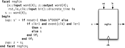
Subsequent chapters will define in detail each element of the facet model, but most elements should be familiar to anyone with software or hardware description language experience. Input and output parameters provide an interface, internal declarations provide state, and the specification body describes properties of the model. Terms in the specification body describe properties declaratively by describing constraints on parameters and internal declarations.
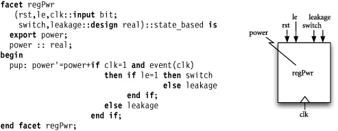
Figure 1.2 shows an alternative model of the same register, but viewed from a power consumption perspective. In this model, data plays no role. The model observes the clock (clk) and load enable (le) inputs to determine if the device switches and updates the consumed power value appropriately. Two design parameters, leakage and switch, allow the specifier to update power calculation constants associated with power leakage and power used when the component switches. The consumed power is observed by examining the exported value regPwr.power at any time during system operation.
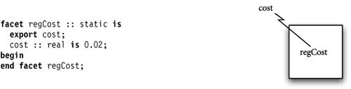
Finally, Figure 1.3 provides a simple cost model for using the register in a system. This is a trivial model providing a constant cost value for each register. In a fashion similar to that of the power facet, the exported regCost.cost value can be used to observe register’s cost. More complex cost models taking into account device width or implementation technology could easily be developed.
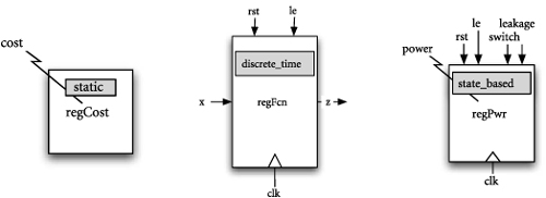
The three register models are quite similar in structure and appearance. Closer examination reveals two fundamental differences among them — interfaces differ from model to model, and each facet is defined with its own domain. Interfaces vary based on the interface of the model represented. The functional model interface looks like one would expect with data inputs and outputs, control inputs, and a clock. The power model is written independently of data inputs and outputs, but adds parameters for adjusting power calculation constants. The cost model is completely independent of inputs and outputs and thus has no parameters. In both the power and the cost models, observable properties are not a part of the interface, but are directly accessed as exported declarations. This distinction is subtle, but important. Cost and power are not system inputs and outputs like data and control, but rather are properties observed over the system as a whole.
Each register model is defined using a different domain. Figure 1.4 shows each facet with its associated domain highlighted. A facet’s domain defines a vocabulary and model-of-computation for the model, allowing each Rosetta facet to use a different semantics. This is critical to system-level design because it allows us to use a semantics appropriate to each model, rather than forcing models to a single semantics. The systems engineer does not force all models into the same semantics, but instead integrates models from different semantics. The key to Rosetta’s system-level design support is this ability to use appropriate semantics for each model and integrate the result into a system-level specification.
The actual register is not any one of the individually defined models, but rather is a system described by those models concurrently. Additional models could easily be written in a similar fashion modeling such characteristics as electromagnetic interference (EMI), analog behavior, setup and hold, and packaging properties. To model the entire register, we must assemble the register facets into a composite register model. To do this, we will use Rosetta’s product operator to assert that the models all describe the same register.
The product operator is rather innocent looking, but is exceptionally powerful in application. Quite simply, if F1 and F2 are both facets, then F1 * F2 is a new facet that embodies both of the original facets. Thus, the Rosetta declaration:
reg(x::input word(4); z::output word(4);
    rst,le,clk::input bit;
    switch,leakage::design real) :: static is
  regFcn(x,z,rst,le,clk) * regPwr(rst,le,clk,switch,leakage) * regCost;
puts all the register models together into a single model, reg, that embodies each of the original models. Whenever reg is used in a specification, all facets comprising that model are present and must be consistent. Figure 1.5 graphically shows the model resulting from the product as a collection of facets “stacked,” representing vertical decomposition of the single component.
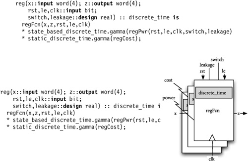
The model in Figure 1.5 is somewhat different than the pure product model for reg. The preceding reg product reduces each model to a least common semantics, that being a model in the static domain. This defeats the purpose of using multiple domains. What we want is to move models to the most appropriate domain for the kind of analysis needed. The following register model does this using functors on facet models:
This new reg model creates a model in the discrete_time domain and the two gamma functors move the regPwr and regCost models to the discrete_time domain. The product is then formed in that domain without loss of design abstractions used in the functional model. This is key to Rosetta design and usage. Information is moved from one modeling domain to another to preserve or introduce design abstractions useful for analysis. Together, functors and products define the central features of the Rosetta interaction system.
Another important aspect of the Rosetta interaction system is the facet combinator. The product operation assembles individual facets into composite system models. The facets still exist within the product as separate, orthogonal models. In effect, the product packages up individual models into a single structure and can still be referenced as individual models. Facet combinators take facet constructions like products and compose their properties into a single facet model, allowing the systems engineer to express interactions.
If we want to write more sophisticated power consumption models that take into account actual data processing and processor behavior, we can write a combinator between the functional and power models. Such a combinator would be used in a specification as follows:
regFcnPwr(x:: input word(4); z:: output word(4);
   rst,le,clk:: input bit;
   switch,leakage:: design real) :: discrete_time is
  fcnPwrComb(regFcn(x,z,rst,le,clk),
     state_based_discrete_time.gamma(regPwr(rst,le,clk,switch,leakage)));
This definition uses the gamma functor to move the power model into the discrete_time domain and then the fcnPwrComb to compose the resulting model with the register’s functional model. In this new model, the power will be an observed property in the same manner as the original model. Thus, regFcnPwr.power will be a defined, observable value that accounts for the register’s functional behavior. The result is a much more accurate model.
Among the most commonly used engineering design techniques is structural decomposition, where a system is represented or implemented as a collection of subsystems. The impacts of decomposition in this manner are obvious when considering the reduction in complexity of models and components. In addition to vertical decomposition, Rosetta’s facet modeling system supports structural decomposition, where a system is defined as a collection of interconnected components.
Figure 1.6 shows a simple structural model using the reg model developed previously. The form of this model should be familiar to those experienced with hardware description languages. Shared declarations are used to communicate between the various system components. All system components are modeled similarly to the register, with various models representing different system facets.
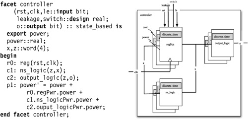
A distinctive feature of this structural model is the calculation of system power consumption from component power consumption values. Here, the power models associated with each component are extracted, then power values extracted and added to the cumulative power consumption value. We are mixing structural models with property models to calculate system-level performance values. The power consumption of our system can be observed as controller.power, allowing the systems engineer to observe changes in system power consumption resulting from local design decisions.
Of course, the hierarchy of Rosetta models is not strictly one level deep. New models may be defined and composed with the structural controller model in exactly the same manner as for the original register model. It is quite common for a system to be described using multiple architectures. One common example of this occurs when an embedded system is described as a process diagram and simultaneously in terms of its implementation architecture. Figure 1.7 shows such a situation for our controller example.
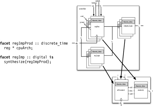
Figure 1.7 graphically shows two architectures for our controller system. One is the controller architecture developed previously. The other is an implementation architecture involving a central processing unit (CPU) and a memory block. The first Rosetta definition forms the product of these models to indicate that they both describe the system we are constructing:
facet regImpProd :: discrete_time is reg * cpuArch;
The regImpProd model describes a system that functions like reg and whose implementation is structured like cpuArch. However, the actual implementation is not yet known — only the fact that our final implementation exhibits both sets of properties is.
The second Rosetta definition is a facet combinator that synthesizes an implementation from the two models:
facet regImp :: digital is synthesize(regImpProd);
The regImp fact is formed by synthesizing a model from the functional and structural models with the facet combinator synthesize. One should quickly recognize that the synthesize combinator is not at all a trivial function to write, and Rosetta provides no silver bullet for addressing this problem. However, it does allow us to define relationships between models that support verification and traceability in the systems design process.
Once a system has been designed and fielded, it is easy to lose track of design assumptions that govern its use and testing. Such information is virtually impossible to glean from an existing system, yet it is vital to the systems engineer. When a system is initially fielded, the systems engineer must understand preconditions for and implications of proper operation. After a system has been fielded and must be updated or replaced, the same information is vital for understanding design context. Knowing what operating conditions were anticipated for a system (as well as what should be observed during operation) dramatically simplifies the system design task.
Rosetta provides a component construct for recording operating preconditions and implications. The component construct is in all ways a facet and can be used anywhere a facet is used. However, the component provides mechanisms for specifying preconditions and implications for using the represented system.
Figure 1.8 shows a component defined around the functional register model. The definition of the register remains unchanged. In fact, the component model references the regFcn model as its definition. The assumptions section places usage requirements on the component. In this case, the only specified usage requirement is that the frequency must be less than 5 GHz. This condition must be satisfied by any system using the component before proper operation can be assured. If we included this component in the previous structural model, we would be obligated to assure this condition based on known facts about the operating environment. The implications section defines correctness conditions on the component. The systems engineer must be able to infer these conditions from the system requirements and usage assumptions.
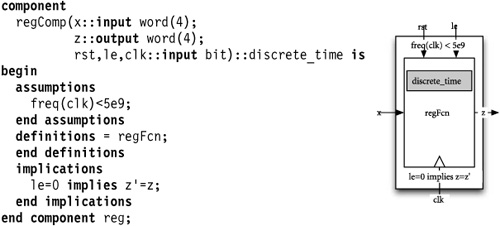
The component structure provides a semantics for expressing and verifying usage conditions and implications, but does not place strict requirements on the verification mechanism. This is due to the wide variety of verification mechanisms used in systems design, ranging from simple observations to formal verification. Rosetta does provide a justification language for recording verification support, but it is used only for recording support and is not a verification language.
Learning Rosetta is as much learning a methodology as learning a new modeling language. Although the register example is quite small, it demonstrates many of Rosetta’s features that enable approaching design in new ways. From support for heterogeneous modeling to using facet combinators to generate models, the modeling process becomes a part of the model itself.
As we step through Rosetta modeling capabilities in detail, we will place them in the larger context of supporting system-level design. The remainder of the text builds Rosetta up from the bottom, starting with primitive specification capabilities and working toward functors and specification composition.
Part II presents the Rosetta expression language, the underlying language for writing all Rosetta specifications. The expression language provides a rich type system and expression definition mechanisms for declaring and defining properties over specification structures. The expression language is a lazy, non-strict functional language with no side effects. It supports defining mathematical properties as opposed to writing imperative programs.
Part III presents the Rosetta facet language, the language for defining basic models. The facet language supports defining a collection of terms over parameters and local variables, and identifying a modeling domain. All Rosetta models are based on facet semantics, thus the facet language is the fundamental construct for writing Rosetta specifications. Packages and components are specializations on facets that provide standard means for structuring specifications.
Part IV presents the Rosetta domain and interaction language and the facet algebra for defining modeling domains, composing specifications, and defining various interactions between models. The domain language defines models of computation, modeling vocabularies and elaboration semantics for specifications. The interaction language packages functor, combinator, and translator specifications into constructs that define domain interactions. The facet algebra defines a collection of operations useful for combining specification models in the presence of interactions.
Finally, Part V presents three case studies of Rosetta system specification. The first case study examines a simple register-transfer level (RTL) system. It serves as an introduction to system-level modeling concepts using an example that is familiar to most designers. The second case study examines a time division multiple access (TDMA)-based telecommunications system looking at relationships between design alternatives and power consumption. It examines the TDMA-based system first from a behavioral specification and then expands to demonstrate structural modeling capabilities. The final case study examines simple security requirements in a networking environment, looking at moving a mobile system from one network infrastructure to another. The three case studies involve different issues in different systems, but are all addressed through heterogeneous modeling, model composition, and constructing interactions between models.
By stepping through each part in sequence, basic Rosetta specification techniques can be mastered. In Part II, the reader should concentrate on learning how to express mathematical properties using the Rosetta expression language. In Part III, the reader should concentrate on learning how to use facets and domains to specify system properties around domain-specific vocabulary and computation modeling elements. The expression language is used to define properties, facets are used to encapsulate properties, and domains are used to introduce computation models. In Part IV, the reader should concentrate on specifying different modeling vocabularies, computation models, and relationships between models. Domains are constructed to define basic computation models while interactions are used to model how different specifications interact. In Part V the reader should concentrate on learning how to define systems and specify analysis and synthesis tasks related to multiple design facets. The case studies attempt to provide examples of classic Rosetta specification techniques and provide a departure point for future specifications. Finally, the bibliography lists a number of works that have influenced Rosetta’s design. They include work from formal methods, language semantics and type theory, hardware specification languages, and programming languages.
One thing this text does not try to do is define a complete, unambiguous syntax for the full Rosetta language. Regardless, there is a need to describe syntactic conventions throughout the book. Table 1.1 provides a list of syntax description conventions used throughout the book. Where possible, traditional notations are used.