
Chapter 12
Security on Financial Services
Information in this chapter:
• Market Data Multicast Distribution
• Protocol-Independent Multicast-Source-Specific Multicast (PIM-SSM)
Large financial services companies face many of the security challenges seen by all large distributed companies. They must protect key internal assets while still providing enough access to them for their users. However, since Financial Services is required to process data in near real time, the industry experiences some unique challenges.
Electronic Trading
For many years trading systems have been evolving. Today, computers are used to execute trades with little or no human involvement and, as a result, high-frequency and algorithmic trading has increased significantly in the past decade. By many estimates, these trades account for greater than 60% of the daily market volumes.
The Financial Information eXchange (“FIX”) protocol is a de facto-standard designed to enable electronic transmission of trading information on the Financial Services market. It has experienced wide and rapid adoption as a straightforward, non-proprietary way to communicate between hundreds of brokerage firms, exchanges, and financial service providers. FIX is a real-time, bi-directional session-based communication mechanism that runs over TCP and has been a key driver in the use of computers to generate and execute orders as the system continues to grow at an incredible rate.
Market Data Networks
Knowledge is power and, in the financial services industry, Market Data services are the primary means of providing information. Market Data feeds consist of flows of information distributed to and analyzed by the financial institutions and include pricing information, market news, and other time-sensitive information used to help develop trading strategies. While identical information is provided to each institution, individual firms apply different analytics to the data to create the competitive advantages that allows these firms to succeed.
The Market Data environment is made up of a few basic components. The first is the source of the information, i.e. the content providers. The primary content providers are the exchanges for stocks, futures and options, and news agencies. The data streams generated by these providers are distributed to the financial trading firms or brokerage houses. These firms then use the information to help determine the strategies to stay competitive in today’s quickly evolving financial markets.
Market Data is primarily distributed as a uni-directional, one-to-many application and as such is ideally suited to and implemented using IP Multicast over UDP.
The Industry Trends
The increasing commoditization of high-frequency trading has many organizations looking for competitive advantages. With electronic trading’s increasing bandwidth requirements and demands for a continuous effort to minimize latency, one good advantage is to simply use the fastest network possible. Many firms have shown a direct correlation between meeting these network demands and revenue growth.
Latency
When dealing with latency in most environments, users in other industries think first about voice and video applications over the network and ensuring an appropriate level of latency in order to avoid quality issues such as echo or an uncomfortable lag when trying to communicate between multiple parties. While latency is important to these applications, the acceptable delays are measured in milliseconds. The reality is that with VoIP applications, a delay of 150 ms would be hardly noticeable to the human ear.
When looking at latency concerns in the Financial Service space, however, voice and video concerns are much easier to manage and maintain when compared to the requirements for supporting applications that include the high-speed, ultra-low latency algorithmic trading platforms and the market data platforms that support them where Firewall latency measured in microseconds.
Financial Service Providers
Exchanges and financial trading institutions are dealing with ever-increasing volumes of information and many firms are moving away from traditional self-maintained data centers and leveraging Financial Service Providers’ (FSP) data centers. With latency varying greatly, depending on the speed of the provisioned links and the number of hops along the path, firms are seeing an opportunity to access thousands of new endpoints while increasing throughput, improving latency and the in-house infrastructure maintenance costs.
These providers compete to offer interconnects for critical applications and to protect intellectual properties, helping to provide competitive advantages for the trading firms while increasing network performance and reducing latency to microseconds where possible.
Direct Market Access
As the firms strive to get to the data as quickly as possible, many are looking closer to the source by selecting feeds directly from the exchanges. By directly accessing markets, stock traders interact directly with the exchanges rather than being forced to execute through intermediary stockbrokers. These firms are establishing these Direct Market Access (DMA) feeds and driving competition among the exchanges for the fastest processing times.
The Challenge
With ever-increasing volumes of information needing to be disseminated and the competitive pressures of the industry, all entities are being pressured to interconnect their environments while increasing network performance. With business-critical applications and key intellectual properties defining competitive advantages, securing these connections while trying to reduce the latency is imperative.
The idea of compromising network performance for the sake of security was, at one time, seen as nearly impossible to accept. However, the days when you could get by without a firewall are long gone… as is the thought that a basic firewall is sufficient. In the Financial Services sector, network security is critical to effective data management, business continuity and compliance. With electronic trading and market applications driving an ever more interconnected ecosystem, new challenges arise in ensuring only appropriate communications are occurring.
Network security has become business-critical, but in many cases, network latency is caused by traditional firewalls. Many traditional firewalls typically account for up to 20% of latency in the network. Fortinet’s FortiGate firewalls’ ASIC approach embed purpose-built Network Processors deliver the low-latency, zero packet-loss firewalling, required in these environments with documented latencies averaging 5–7 μs at line rate of 64 byte packets for IPv4 traffic and similar performance metrics from the Security Processors and for hardware acceleration of not only IPv4 traffic, but also IPv6 and multicast acceleration.
While these acceleration capabilities have been discussed earlier in the book, we will not go over this topic again. But there is another key component of the application deployments we just outlined that has not been discussed in detail when it comes to deploying a secured Market Data solution.
Market Data Multicast Distribution
As discussed, Market Data is a one-to-many application with content providers distributing streams of information using IP Multicast so as to not replicate every data packet for each and every user. While many environments solely use Protocol-Independent Multicast-Sparse Mode (PIM-SM), this is suited to Any Source Multicast (ASM) [1, 2]. By this, we mean that the requesters of the data streams receive information by joining a “group” (G) based on the multicast address. These requesters, or applications, are not concerned with the “source” (S) or sources of the stream so long as the network can forward the correct stream to that requestor.
This model can represent some specific challenges for content providers, transmission providers, and the recipient networks of these multicast streams.
Inter-domain Multicast
One challenge when deploying a multicast environment, such as one that would support a market data distribution network, is dealing with the concerns around supporting a multi-domain architecture. While most of today’s environments support a PIM-SM deployment, this works best within a single domain. Where the source or sources for a particular multicast stream may not be well known, a new set of concerns must be addressed when expanding multicast coverage across multiple dispersed networks.
PIM-SM uses a “shared tree” to distribute the multicast stream to the requestors of the multicast group. This tree is represented as a (*, G) tree routed at a “Rendezvous Point” (RP). While we will go into more detail on this process shortly, it is important to understand that the use of an RP is required with PIM-SM.
Needing to statically coordinate the Rendezvous Point deployments in support of PIM-SM between domains can be difficult to support and prone to errors. These errors can cause issues in the neighboring domains. Statically maintaining multicast routes or deploying additional protocols such as Multicast Source Discovery Protocol (MSDP) and Multiprotocol Border Gateway Protocol (MBGP) can help discover multiple sources between domains and propagate multicast routes between domains. This will also provide more opportunities for error and unneeded complexity to be injected into the environment.
These options can clearly lead to an increase in the administrative overhead and the difficulty of coordinating between domains would be exacerbated for the content providers and distribution network maintainers as end users attempt to all get closer to the data. This will, over time, lead to an increase in configuration error. Inter-domain deployment often adds extra complexity to the tasks of maintaining and troubleshooting statically defined networks.
Address Group Collisions
Another concern in an Any Source Multicast environment is address space collision. With the IPv4 address space limited and the limited or experimental designation of actual address assignments within the multicast space, it is very likely that administrators from multiple domains will attempt to use the same address groups for different applications. While this is most likely unintentional, address collision can occur and could consume more bandwidth than expected or send unexpected data to applications, resulting in unexpected behavior.
Protocol-Independent Multicast-Source-Specific Multicast (PIM-SSM)
PIM-SSM is effectively an extension to PIM-SM [3]. While dependent on PIM messaging between routers to create multicast distribution trees, we will review some of the advantages to using PIM-SSM in environments common to Market Data Providers which distribute feeds to many self-maintained network domains.
PIM-SM Operation Overview
In a traditional ASM environment supported by PIM-SM, requesters use IGMPv1, 2, or 3 to request membership into a group. These requests do not include information as to the source requesting the data. If a request is made in a properly configured PIM-SM environment a (*, G) entry will be created on the Rendezvous Point (RP) for the requested address group. Using the administratively scoped address group of 239.10.10.100 as an example, the PIM-SM routers along the path would each create an entry for (*, 239.10.10.100) toward the RP.
The routers closest to the multicast sources are responsible for tunneling the data streams to the RP so those streams can be forwarded by the RP via the shared (*, G) tree when requested to the router ultimately responsible for the receiving host.
Once the final router receives a stream for a given multicast group, it can choose to create a more optimal distribution tree, perhaps by using the actual source as opposed to continuing to use the share distribution tree. This more optimal source-specific path is identified by an (S, G) entry in the router’s multicast routing table. The (S, G) path is determined by routers using the normal routing table to do a “Reverse Path Forward” lookup toward the source and determine the best route back.
Using our 239.10.10.100 example, if we were to receive multicast packets for this group from a source example of 10.10.50.125, we would see a table entry for (10.10.50.125, 239.10.10.100) requesting the stream to be received on the interface perceived as “closest” to the source based on the RPF check of the routing table.
The (*, 239.10.10.100) entry would still exist for any potential new sources for them to forward down the shared tree, again potentially a less optimal path from the new source. The final router receiving the stream on behalf of the requesting host can send another more specific path request toward the new source using another (S, G) entry.
Aside from the complexity of troubleshooting potential problems and the likely less than optimal forwarding for multicast streams via the shared tree, there also exists the chance that we would receive data associated from one or more unwanted sources.
PIM-SSM Operation Overview
When deploying a PIM-SSM environment, hosts use IGMPv3 [4] to request not only group membership but also to define the source or sources from which to receive the groups. This “source, group” paring can be thought of as a “channel.” Channels are discussed and addressed at the application level, but this mechanism helps us to ensure that the application is only receiving multicast packets from the sources specified and that our routers avoid having to maintain a less than optimal shared distribution tree. With PIM-SSM, the routers know the source when the host makes its request allowing the router to create an (S, G) entry from the onset of the communication request. This way there is granular control of our sources, avoiding address collision concerns. There is no need for an RP to support a shared tree and the most efficient route from the onset handles forwarding of multicast packets.
Channel Redundancy
Many applications that tie to financial operations require redundant infrastructure. Market Data solutions are no exception. By supporting the ability to define the source and multicast channels, it is fairly straightforward to deploy content sources in multiple locations and to stream both primary and backup sources for the subscribers’ required channels.
Channel Control
An advantage an application like Market Data has is knowing the source addresses of the channels ahead of time. This allows the ability to ensure, or secure, which channels are to be allowed into a subscriber’s network either by the subscriber themselves or by the content provider.
This also allows for the content providers to plan for appropriate network address translation of the source and/or the destination to be defined per channel.
Configuration Steps to Enable PIM-SSM
To configure our FortiOS device to participate in PIM-SSM, you must perform some fairly simple steps. Before we begin, we must make a few assumptions. The first is that full IP reachability has been established between our multicast requesters and our multicast sources. (S, G) multicast distribution trees are dependent on the ability of each PIM-speaking router in the path to identify an appropriate route to the multicast sources. The second assumption comes in that all routers in the path from channel requesters to channel sources have PIM-SM enabled properly. As mentioned earlier, the use of PIM-SSM is dependent on the use of PIM messaging to create and maintain the (S, G) distribution tree. We will review the basic configuration of PIM-SM in FortiOS during this walk through.
Defining Address Range
When configuring PIM-SSM, we will want to define the range of multicast addresses acceptable for source-specific requests. To do this, use an “access-list.” The below example shows an access-list that defines the 232.0.0.0/8 subnet as outlined for use with PIM-SSM in RFCs 3569 and 4607.
Controlling SSM Channel Assignments
By using the “multicast-flow” command we can create channel and control the source and destination pairs that can be joined on each interface using SSM. The following example shows a multicast-flow configured with a single flow from source 10.10.25.125 providing a stream to multicast group 232.10.45.15.
It should be understood that the use of the “multicast-flow” option does not negate the need to use multicast policies to allow traffic to flow through the system. The use of multicast firewall polices was covered in an earlier chapter. Multicast firewall policies are also used to provide network address translation of either the source address and/or the multicast group address.
Enabling Multicast Routing
Now that the prep work has been accomplished, we can configure FortiOS to participate in the PIM environment. As we are not concerned with participating in any (*, G) distribution trees, our configuration is very simple.
In the example, we can see that we have enabled multicast routing as well as the use of PIM-SSM. The second SSM option defined in the example is that of the multicast address range allowing use in SSM by referencing the access-list created during our prep work.
As we continue this configuration, we will assume that the FortiGate is to route traffic between the “internal” and “wan1” interfaces. We will want to enable PIM-SM on these interfaces for our firewall to participate in the creation of our multicast distribution trees. FortiOS interfaces default to IGMPv3, so we will not need to configure any other option at the interface level.
While there is no further configuration required, we have taken an additional step by applying the “multicast-flow” we defined earlier. As discussed previously, applying this configuration to the interface will restrict the channels that IGMPv3 clients can successfully request. There is no implicit deniar when using “multicast-flow,” so if there is no “multicast-flow” applied to the interface, there will be no restrictions applied.
Monitoring IP Multicast
When ensuring a network environment can support the distribution of multicast streams, many of the tools described earlier in this book will come handy. Full IP reachability must be established before we can properly set up any multicast routing.
Assuming this has been done and all is functioning well, there are a couple of key commands to be familiar with when establishing your IP multicast networking.
PIM Interfaces
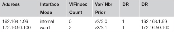
One of the first things you may need to verify is that you have enabled PIM-SM on the interfaces as required. The following command will show the interfaces with PIM-SM enabled, which interfaces have PIM neighbors, and the IP address of the PIM designated router on each interface segment.
FWF60C # get router info multicast pim sparse-mode interface
PIM Neighbors
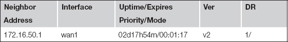
For a more detailed view of the health of your neighbor relationship, the following command will show you the IP address of any PIM neighbors, the interface on which they are peered, and the time your neighbor relationship has been established.
FWF60C # get router info multicast pim sparse-mode neighbor
IGMP Interface Verification
While IGMPv3 is the default, the following command can verify that the interface is configured and operating as required working with PIM-SSM.
FWF60C # get router info multicast igmp interface
IGMP Enabled, Active, Querier, Configured for version 3
Internet address is 192.168.1.99
IGMP query interval is 125 seconds
IGMP querier timeout is 255 seconds
IGMP max query response time is 10 seconds
Last member query response interval is 1000 milliseconds
IGMP Group Membership
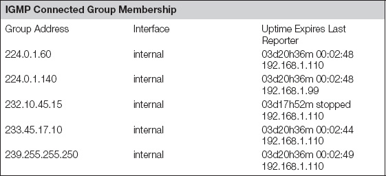
Once we have confirmed configuration, one of the next items is to verify the IGMP group membership requests received by the firewall. The following command will show the groups requested on each interface as well as the address of the requester.
The expiry timer shows when the forwarding of the groups will end if no further updates or continuation requests are seen. The status of “stopped” for group 232.10.45.15 is an IGMPv3 source-specific joint and indicates that this timer does not determine the expiration of this group.
FWF60C # get router info multicast igmp groups
Multicast Routing Table
Once we have verified that the expected request is made, we can verify the expected route in the multicast routing table. The following command finds and verifies the entry for the multicast channels being created and distributed correctly.
The table snippet shown below confirms we are receiving for the group and identifies the source or sources. Two important things to verify are the “Asserted” or incoming interface and the “Outgoing” interface of the channel. The “Asserted” interface is determined by the reverse path look up toward the sources. If there is an unexpected result in this field, troubleshoot the normal IP routing table to verify the correct route to the source.
The outgoing interface is created toward any IGMP interfaces with requesting host and/or interface with PIM neighbors that have requested the stream to forward further into the distribution tree.
The trailing address used in this sample is optional. Leaving it off will provide output for the entire IP Multicast routing table.
FWF60C # get router info multicast pim sparse-mode table 232.10.45.15
Debugging PIM-SM Messages
The previous “get” commands will normally provide enough information for you to confirm proper operation or to diagnose any issues you may be experiencing. However, there will always be those times when you must go just a little deeper to determine why things may not be operating as planned.
Debugging PIM events requires first choosing the PIM event output you want to witness. By default, all PIM event message types are enabled. If setting the event level to informational provides too much output, disabling events or message types that are not of interest is advisable. As with any debug-level troubleshooting, the use of the “diag debug enable” command is how you start getting output.
You can see some examples of the commands used and a sample output of PIM events from an information output.
FWF60C # diagnose ip router pim-sm level
| critical | critical level |
| error | error level |
| info | information level |
| none | none level |
| warn | warning level |
FWF60C # diagnose ip router pim-sm level info
FWF60C # diagnose ip router pim-sm show
Debugging status:
PIM Hello HT timer debugging is on
PIM Hello NLT timer debugging is on
PIM Hello THT timer debugging is on
PIM Join/Prune JT timer debugging is on
PIM Join/Prune ET timer debugging is on
PIM Join/Prune PPT timer debugging is on
PIM Join/Prune KAT timer debugging is on
PIM Join/Prune OT timer debugging is on
PIM Assert AT timer debugging is on
PIM Register RST timer debugging is on
PIM Bootstrap BST timer debugging is on
FWF60C # diag debug enable
id=36870 msg=”PIM-SM: PIM Assert from 172.16.50.1”
id=36870 msg=”PIM-SM: Recv Assert message”
id=36870 msg=”PIM-SM: Group: 232.10.45.15/32 (Family 1, Type 0)”
id=36870 msg=”PIM-SM: Source: 10.10.25.125 (Family 1, Type 0)”
id=36870 msg=”PIM-SM: R-Bit: 0”
id=36870 msg=”PIM-SM: Preference: 10”
id=36870 msg=”PIM-SM: Metric: 0”
id=36870 msg=”PIM-SM: MRIB.pref(10.10.25.125): nexthop 172.16.50.1 preference 10”
id=36870 msg=”PIM-SM: MRIB.metric(10.10.25.125): nexthop 172.16.50.1 metric 0”
id=36870 msg=”PIM-SM: MRIB.pref(10.10.25.125): nexthop 172.16.50.1 preference 10”
id=36870 msg=”PIM-SM: MRIB.metric(10.10.25.125): nexthop 172.16.50.1 metric 0”
id=36870 msg=”PIM-SM: Receive Acceptable Assert from Current Winner for (10.10.25.125, 232.10.45.15) on wan1”
id=36870 msg=”PIM-SM: Assert (10.10.25.125, 232.10.45.15) on wan1: Restarting AT timer with 180 secs timeout”
id=36870 msg=”PIM-SM: PIM Hello packet Recved.”
id=36870 msg=”PIM-SM: PIM Hello from 172.16.50.1 on wan1”
id=36870 msg=”PIM-SM: Recv Hello message”
id=36870 msg=”PIM-SM: Holdtime: 105
id=36870 msg=”PIM-SM: T-bit: off”
id=36870 msg=”PIM-SM: Lan delay: 1”
id=36870 msg=”PIM-SM: Override interval: 3”
id=36870 msg=”PIM-SM: DR priority: 1”
id=36870 msg=”PIM-SM: Gen ID: 1212108891”
id=36870 msg=”PIM-SM: Restarting NLT for neighbor 172.16.50.1 on wan1 with 105 secs timeout from Hello message”
id=36870 msg=”PIM-SM: Hello Timer expired on internal”
id=36870 msg=”PIM-SM: Restarting Hello Timer on internal with 30 secs timeout”
id=36870 msg=”PIM-SM: Stopping Triggered Hello Timer on internal”
id=36870 msg=”PIM-SM: Hello send to internal”
id=36870 msg=”PIM-SM: Send Hello message”
id=36870 msg=”PIM-SM: Holdtime: 105”
id=36870 msg=”PIM-SM: T-bit: off”
id=36870 msg=”PIM-SM: Lan delay: 1”
id=36870 msg=”PIM-SM: Override interval: 3”
FWF60C # diag debug disable
FWF60C # diagnose ip router pim-sm level critical
Debugging IGMP Messages
Debugging IGMP messaging is nearly identical to that for PIM messages.
Debug-level messages and message types are configured as in the examples. Like the PIM message debug output, the IGMP message debug output can be overly verbose and it can help to enable and disable different message types in addition to setting the debug level.
FWF60C # diag ip router igmp show
FWF60C # diag ip router igmp level info
FWF60C # diag debug enable
id=36870 msg=”NSM: [IGMP-ENCODE] Send Gen Query: Sent General Query on internal, ret=36”
id=36870 msg=”NSM: [IGMP-DECODE] Dec Msg: IGMP Membership Query, Max. Rsp. Code 100”
id=36870 msg=”NSM: [IGMP-DECODE] Dec Msg: IGMP V3 Membership Report, Max. Rsp. Code 0”
id=36870 msg=”NSM: [IGMP-DECODE] Dec V3 Grp Rec: Grp 239.255.255.250 on internal”
id=36870 msg=”NSM: [IGMP-FSM] Process Event: I=internal, G=239.255.255.250, State: Exclude, Event: Mode Is Exclude”
id=36870 msg=”NSM: [IGMP-FSM] State Change: Exclude(2)->Exclude(2)”
id=36870 msg=”NSM: [IGMP-DECODE] Dec V3 Grp Rec: Grp 224.0.1.60 on internal”
id=36870 msg=”NSM: [IGMP-FSM] Process Event: I=internal, G=224.0.1.60, State: Exclude, Event: Mode Is Exclude”
id=36870 msg=”NSM: [IGMP-FSM] State Change: Exclude(2)->Exclude(2)”
id=36870 msg=”NSM: [IGMP-DECODE] Dec Msg: IGMP V2 Membership Report, Max. Rsp. Code 0”
id=36870 msg=”NSM: [IGMP-DECODE] Dec V2 Report: Grp 224.0.1.140 on internal”
id=36870 msg=”NSM: [IGMP-FSM] Process Event: I=internal, G=224.0.1.140, State: Exclude, Event: Mode Is Exclude”
id=36870 msg=”NSM: [IGMP-FSM] State Change: Exclude(2)->Exclude(2)”
id=36870 msg=”NSM: [IGMP-DECODE] Dec Msg: IGMP V3 Membership Report, Max. Rsp. Code 0”
id=36870 msg=”NSM: [IGMP-DECODE] Dec V3 Grp Rec: Grp 232.10.45.15 on internal”
id=36870 msg=”NSM: [IGMP-FSM] Process Event: I=internal, G=232.10.45.15, State: Include, Event: Mode Is Include”
id=36870 msg=”NSM: [IGMP-FSM] State Change: Include(1)->Include(1)”
id=36870 msg=”NSM: [IGMP-DECODE] Dec Msg: IGMP V2 Membership Report, Max. Rsp. Code 0”
id=36870 msg=”NSM: [IGMP-DECODE] Dec V2 Report: Invalid Grp 224.0.0.22 on internal, Ignoring...”
id=36870 msg=”NSM: [IGMP-DECODE] Dec Msg: IGMP V3 Membership Report, Max. Rsp. Code 0”
id=36870 msg=”NSM: [IGMP-DECODE] Dec V3 Grp Rec: Grp 233.45.17.10 on internal”
id=36870 msg=”NSM: [IGMP-FSM] Process Event: I=internal, G=233.45.17.10, State: Exclude, Event: Mode Is Exclude”
References
1. RFC 3569—An Overview of Source-Specific Multicast (SSM).
2. RFC 4607—Source-Specific Multicast for IP.
3. RFC 4601—Protocol Independent Multicast-Sparse Mode (PIM-SM): Protocol Specification.
4. RFC 4604—Using Internet Group Management Protocol Version 3 (IGMPv3) and Multicast Listener Discovery Protocol Version 2 (MLDv2) for Source-Specific Multicast.