
Chapter 3
FortiOS Introduction
Information in this chapter:
• Recommended Configuration Options
- Controlling Administrative Access
- Specifying the source IP address for FortiOS originated traffic
• Advanced Configuration Options
• Dealing with Administrative Operations
Fortios Architecture
The firmware used on FortiOS is delivered as a single consolidated image containing the kernel, user-space applications, and initial signature databases. By not having to download modules for installation, the FortiGate appliance can immediately provide application layer protection.
The kernel follows the POSIX standard and includes the traditional separation from user-space applications. The kernel provides enough services to support a security-focused system and interface for more flexible applications to use. Fundamentally, the role of the kernel is to serve as a bridge between the hardware and the applications. As mentioned in the previous chapter, FortiOS devices include general hardware like Ethernet interfaces and custom-built ASICs.
Like a networking stack that’s based on the OSI seven-layer model or a server with dedicated hardware, kernel, and user-space applications, the FortiOS is layered. The first layer consists of the actual hardware that makes up the appliance. All FortiGate appliances contain at least the following hardware: CPU, RAM, network interfaces, ASIC Content Processor, and a form of permanent storage. Further details on hardware can be found in Chapter 2. Recently, Fortinet has introduced a System-on-a-Chip (SoC) design for entry level. This design includes all of the hardware mentioned as well as integrates elements of the Network Processor (NP) and Content Processor (CP) hardware to accelerate firewall performance.
The second layer includes all software components that provide access to the hardware layer. These are often referred to as “device drivers” and may be compiled into the kernel itself (layer 3). As the hardware components will slightly differ from model to model, the drivers will as well. For example, lower-end systems may use Intel or Broadcom network devices, while higher-end systems will rely on an ASIC. Different hardware will require different drivers. Since some drivers are compiled in, this means that different FortiGate models will necessarily require different firmware. In addition, the FortiNPU layer provides a common interface to FortiOS for the various hardware combinations.
The third layer is the kernel or Operating System (OS) layer. Like kernels in other OSs, it has direct interaction with the device drivers at Layer 2 and provides interfaces to the user-space applications. This enables Fortinet to rapidly deploy new features onto the FortiGate devices. To provide maximum performance, the firewall engine is implemented in the kernel. This allows it to efficiently interact with the interrupt handling, task scheduling, and memory management subsystems. Integration between the kernel and the firewall engine allows for other applications to communicate with layer 3 through pipes and shared memory access.
The fourth layer is composed of the user-space applications. These applications access the kernel using the internal Application Programming Interface (API). These APIs are internal and intended for Fortinet developers. They are not made available to third parties as they might change without notice. Most of the remaining functionality in FortiOS devices is implemented in individual applications at this layer. Commonly used applications include transparent proxies and the AV and IPS engines.
The final layer is the configuration layer, which consists of the Web and Command Line Interfaces (WebUI and CLI). Whether accessing the configuration through the web interface running on the built-in web server or through shell commands, the configuration itself is stored internally as a text file. CLI configuration commands can be entered in via SSH or on the console port during the POST process. Console access requires your terminal emulator to be set for 9600-N-8-1. For systems that support multiple FortiOS images, the config file is stored with each corresponding image.
Multiple Image Support
Modern FortiGates include permanent storage that is used for both the firmware image and the configuration of that image. While the type of storage may either be Flash or NAND RAM and the amount varies by hardware model, the storage itself is divided into three separate file systems. The first two contain copies of the firmware image and associated configuration file. This provides a backup and recovery system, should a firmware update experience difficulty. During normal operations, only the active file system is mounted by the OS.
You can define which firmware image is Active image via the Web UI, or the CLI. From the Web UI, navigate to System → Dashboard → Dashboard then click on ‘Details’ at the end of the Firmware Version line. From the CLI you can use the “diag system flash list” to list the images on each of the partitions, and “exec set-next-reboot primary | secondary” and to select the partition to boot from during the next reboot. When displaying the partitions, partition number 1 is considered the primary and partition number 2 is the secondary. You can also select the firmware image to boot from the system BIOS during boot via the console port. When you boot, simply press a key when prompted and select to boot the “Default” or “Backup” from the menu.
The third file system contains the most recently downloaded signature database for each service that is licensed and activated. In order to provide a baseline level of security, each firmware image incorporates the AV and IPS database that was current when the firmware was released. Thus, even if there is a problem downloading the latest set of AV and IPS protections, some protection is available.
Firmware Image Versions
All Fortinet firmware images follow a standard naming/numbering convention. The named scheme includes the Major, Minor, and Patch release numbers. The alternate, and more common, naming scheme simply consists of those three numbers separated by periods. Major number releases, the first of the set, are released approximately every four years. Minor numbers, generally every six months and patch releases as needed. Major releases typically contain new functionality. Minor releases include enhancements to the existing feature set and patch releases simply fix known issues. An alternative method long form for describing the release is also found, for the previous example this method would be written 4.0 MR3 Patch 2, MR denoting Minor Release.
There could be as much as 20 months after the initial 4.0.0 release to the 4.3.2 version, as three Minor releases must have been released and two patches for the current version. A Fortinet Major release has a relatively long lifespan.
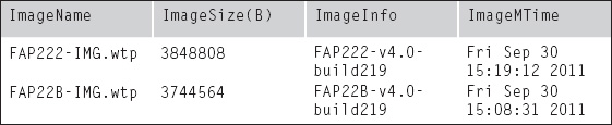
These releases all correlate to a specific build, and this build number is references where the firmware is displayed (WebUI system information widget, CLI “get system status” command, and the configuration backups). This number is considered the most accurate information regarding the firmware that you’re running, so Fortinet support may ask for this number in preference to the Major.Minor.Patch number. Tospeed things up, it would be wise to always run the “get system status” command and copy the output to the technical support engineer. This way, they will have access to all hardware details, serial number, firmware version, and BIOS level.
Fortinet makes every attempt to keep the releases consistent across all models. Thus, when a new Minor release is available, it is released on all currently supported systems. When a new Major release becomes available, the Minor versions for the older Major releases are usually halted at their current level. Patches may be released as needed, but any feature enhancements will focus on the most current Major releases. Fortinet’s policy is to maintain the current and immediately previous Minor releases.
FortiOS Operational Modes
FortiGate devices can run in two modes: Layer 3 or Layer 2. Layer 3 is the more traditional operating mode and works much like other firewall products. In this mode, which Fortinet refers to as “NAT/Route”, each interface has an IP address and makes routing/forwarding decisions like a traditional router.
However, Layer 2 mode is much less common. Referred to as “Transparent”, it allows the Fortinet to be introduced to a network without requiring changes (IP addressing, routing) to the surrounding Layer 3 environment. This is particularly helpful when the FortiGate is providing security augmentation or visibility beyond traditional Layer 4. In other words, if device is being used to provide UTM features, but should not interfere with the filtering capabilities on the existing firewalls, it can easily supplement the network with Web Content Filtering or IPS functions.
Another interesting outcome of the transparent mode configuration is that the FortiGate can now be placed in the middle of an existing 802.1q trunk and provide security for multiple VLANs (Virtual LANs) at the same time. The 802.1q specification provides a method for allowing multiple distinct networks to operate on the same physical infrastructure, creating a virtual infrastructure on top of the physical one. Packets are identified as belonging to a specific virtual infrastructure (or VLAN) by the value of the VLAN tag added to the packets, if there is no VLAN tag in the packet header then the packet is commonly referred to as being untagged, or as some vendors refer to it, being in the Native VLAN. The FortiGate uses these tags the same way, identifying packets belonging to a specific virtual infrastructure by the value of the VLAN tag. For more specific details on the 802.1q specification, please see the standard documents from the IEEE (International BLAH BLAH BLAH) where configuring VLANs is covered in some detail in Chapter 4. Of course appropriate sizing is required for this to work without providing unacceptable latency on all the traffic.
There is even a CLI configuration option that tells the FortiGate to forward all VLAN-tagged packets as-is without any type of inspection. Thus, all traffic is passed, but if a particular VLAN-tagged communication needs to be inspected, the administrator can add a pair of interfaces. By defining ingress and egress interfaces for a specific VLAN, that traffic can be inspected without slowing down the rest of the network.
When configured in Transparent mode, the FortiGate operates like a very smart Layer 2 bridge or switch. For example, when an ARP request is received on an interface, the FortiGate consults its MAC table and if it is not already known, the FortiGate sends the ARP request out to all other operating interfaces in that VDOM. Once an ARP reply is seen on an interface, the MAC address is added to an internal table. Then, since the source and destination addresses are known, the firewall policy can be evaluated. If the firewall policy allows the traffic, then the packets received on the ingress interface are rewritten to the egress interface with no changes. This means that the MAC addresses remain the same, so the FortiGate is effectively invisible to the network.
This bridge/switch like behavior also allows end systems to directly connect to the FortiGate, so all security enforcement is performed on the FortiGate itself. This greatly simplifies the process of maintaining security on multiple systems with various OSs. Transparent mode also includes the ability to terminate IPSec tunnels and perform NAT operations, this is configured as an advanced configuration but basically these operations are performed by treating the management IP address assigned to the VDOM like a gateway, this is the address that the IPSec tunnels originate from or are destined to, for example.
Packet Flow Handling
Like everything else, network speeds have increased over time. As a result, security operations must be performed at ever-increasing rates. To help address this, FortiGate appliances that include the SP module can offload not just Layer 3/4 firewall processing, but also full Layer 7 processing. This speeds up analysis by the IPS and Application Control engines.
Generally, FortiOS will process packets in layer order. Thus, Layer 2 checks happen first, followed by Layer 3 processing and all the way up the OSI model. Layer 2 checks include evaluating the packets for integrity (checksum), identifying whether the packet is IP-based and, if so, forwarding it up the processing stack. Non-IP packets are processed if the FortiGate is configured to do so, usually only in Transparent mode.
As soon as the Layer 3 information is available, FortiOS compares the destination IP address to the routing table in order to determine the egress interface. The destination IP address is also compared against other possible terminations: IPSec tunnels, SSL VPNs, and WAN routes. Packets that must be decrypted are processed first, using the cryptographic engine present in the NP or SP or, if neither are available, by the CP. The decrypted packet is then passed along to the firewall engine.
At this point enough information is available to evaluate the packet against the firewall policies. The packet’s Layer 3 and 4 information is evaluated against the rules in each policy, in top-down order with the first match winning. While security policies that are source and destination-specific are considered more secure, FortiOS allows you to define non-interface-specific rules by setting the policy to the “any” interface. This is often considered easier to manage, albeit at the cost of decreased processing efficiency and a slightly higher chance of unanticipated results in edge cases.
If the packet matches an identity-based policy, then further evaluation occurs. The next process checks the user-authentication database, matching the source IP address against the known users, if no match is found then the traffic is matched against the Guest Access group.
Once a policy has been matched for a packet, the type of processing is determined. This is where packets are optionally passed on to UTM processing. If there is no UTM configured for the matching policy and the hardware platform has a Network Processor (NP), then a session-key is pushed down to the NP so that any future packets associated with this session can be accelerated. If a UTM feature is active and it makes use of the IPS Engine and there is a Security Processor (SP) present, then the session information is pushed down to the SP so that the session can be locally processed. If the policy requires the intervention of a transparent proxy or if a SP is not present, then the traffic is handled by the main CPU. The CPU also processes other features such as SSL-VPN, WAN optimization, etc.
WebUI Management Interface
The most-often used administrative interface for FortiGate devices is accessed via a standard web browser. The interface is wholly contained within the FortiGate and does not rely on any external systems or services. Most operations can be performed with this WebUI, however a small number of advanced operations require the command line interface (CLI). This can be accessed directly over SSH or through a widget located within the WebUI itself.
By default, FortiGate devices have either the internal or port1 interfaces configured to have an IP address of 192.168.1.99/24 and to listen for the HTTPS on port 443. For reasons of simplicity, the devices created for the smaller market (SOHO, Remote Office, and Small Enterprise… all devices smaller than the 200B) also listen for HTTP on port 80. These devices also simplify setup by running a DHCP server. If they are added to an environment that already has a DHCP server, two problems could arise. If the local network is 192.168.1.*, the possibility of conflicting IP addresses exists, which could take one or both systems offline. If the local network is anything else, there is the possibility that the wrong IP address could be assigned, which would prevent that system from accessing the network.
These are classic security vs convenience tradeoffs. So, if you have one of these units, it would be wise to disable the unneeded services once the FortiGate is initially configured. Note, though, that changes on a FortiGate are made immediately once the “OK” or “Apply” buttons are clicked. Thus, if you disable the HTTP access and you are using that access, you will need to reconnect over HTTPS as soon as you disable HTTP.
The WebUI also supports widgets other than the option to embed the CLI. These widgets are user configurable and can be added to the system dashboard or to any custom dashboard that you create to provide specific views into your network activities.
CLI Management Interface
Advanced users often prefer the command line interface to a WebGUI. The CLI is exactly the same regardless of how it is accessed, whether that is via the physical console port, across the network using SSH or telnet, or via the integrated WebUI console widget. CLI commands follow a branching model, with four primary areas: config, diag, exec, and get/show.
| config | Precedes any command that alters the Operating Configuration. These changes are stored to the permanent configuration |
| diag | Precedes commands used to perform troubleshooting operations, if the command results in a change to the operating configuration of the FortiGate these changes are not saved to the permanent configuration, so if you reboot the device, they will be undone |
| exec | Precedes the CLI commands used for routine operations. Some are related to troubleshooting such as ping and traceroute while others are related to system operations and maintance, such as performing a backup or requesting signature updates |
| get | Used to view the current operating value for all options of a configuration element. Unlike “show”, this includes all values, whether they are defaults or changed |
| show | This option allows for the current settings for a configuration element to be displayed, but unlike “get”, only displayed the values that have been changed from the defaults |
To help you navigate the CLI, you can use the “?” and [Tab] shortcuts. Entering “?” at any point will give you a context-sensitive list of valid options and the “Tab” key will cycle through those options.
The CLI is highly structured and is intended to match the layout implemented in the WebUI as much as possible. For example, the “config” suboptions mirror the main menu options in the WebUI: config system, config firewall, config router, etc.
A number of configuration elements are stored and accessed in a list-like structure. This is mostly true for elements which are one of many, such as interfaces (port0, port1, port2, etc.), policies, addresses, and services. When configuring these elements, the “next” command indicates that you are done configuring the current element in the list and are ready to move on to the next one. The “end” command indicates that you are done configuring that list and are ready to go back to the previous level.
It should be noted that the CLI syntax is case-sensitive, so the word “this” is not the same as the word “This”. Since the system is object-based, you can therefore create objects that differ only in capitalization. This can obviously become very confusing, so it is recommended that you decide on a standard style (such as lowercase, Initial Caps, CamelCase, or ALLCAPS) and stick to that as much as possible. This way, you can use an alternate case to highlight items as exception or out of the norm. An example of this would be having rules like: “block inbound http”, “allow outbound ssh”, and “DEBUG – ALLOW HTTP TO SERVER2”.
When working with the CLI it is important to note that, as and when you click “OK” or “Apply” in the WebUI, the configuration changes are immediate when you run a “next” or “end” command. In some cases there is also the option to abandon a partial set of changes by issuing the “abort” command.
If you enable VDOMs, be aware that you are adding a layer of complexity. To manage this additional layer, you will see a separation at the top of the CLI command tree that isolates global configuration options from VDOM-specific configuration options. So the highest level of the CLI tree consists of only the config option, and a single get command (get system status), the config option then accepts only two suboptions: “global” and “vdom”, so you can choose which mode to enter. To keep you from being confused, the CLI prompt also changes to reflect the mode that you are in.
System Options
Recommended Configuration Options
There are some configuration options that in their default configuration don’t really result in a very secure implementation, some of these are more related to ease of use and should really be disabled. There are other options that are often considered to be best practices for configuring security devices.
Configuring Logging
FortiOS has extensive logging support. This is used, not just for generating traffic and security logs, but also for system operations and auditing system configuration changes. Log messages can be sent to many different types of servers, including Fortinet’s own FortiAnalyzer (see Chapter 8 for more information), industry standard Syslog Servers using either unreliable UDP transport1 or reliable TCP transport2 as well as the WELF log format as originally specified by Webtrends Corporation. Though the WebUI only supports one target, both FortiAnlyzer and Syslog messages can actually be specified to up to three logging servers, each with their own configuration (see Figure 3.1). However, only one Webtrends server is supported within FortiOS and that configuration is CLI-only. In addition to remote logging, the FortiGate also has the ability to save log messages in memory or local storage, if space is available. Ofcourse the amount of log messages that can be stored in memory is very small (approx 128 logs per message type) and they roll out the bottom when a new message appears, with local storage the log files are rolled out periodically with the oldest logsautomatically deleted when the storage space reaches 80% of it’s available capacity.
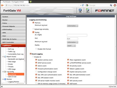
Figure 3.1 Configuring Logging
Fortinet also offers a cloud-based/SaaS logging solution known as FortiGuard Analysis & Management Service (FAMS). This is intended for smaller organizations, as they are unlikely to have invested in central logging infrastructure. Inaddition to logging, this service also offers a configuration repository to allow you to track your configuration changes over time.
You can specify the type and severity of log messages sent to each logdestination. This allows you to only send the appropriate log messages, simplifying analysis and reducing storage requirements. For example, if your Security Event and Incident Management (SEIM) system is only reporting on Security events, there is no point sending Network (traffic log) messages to it. The same goes for network-trending analysis that has no need for Security logs.
There is very granular configuration of what logs are sent to each destination. Each log message also has a severity level and you can configure what level messages are sent to each destination. This allows you to leverage, for example, an existing Syslog system that can be used to send SMS messages or emails on critical events. Setting that destination to only receive messages of warning or greater severity will reduce the number of false alarms. You can review the severity available for log messages in the Log Reference Guide on http://docs.fortinet.com.
The CLI configuration commands for each destination vary slightly as they have different capabilities and therefore different configuration requirements.
set reliable disable ← enabling this turns on reliableset port 514syslog (syslog over TCP)
set csv disable ← some systems prefer the keyword=value pairs to be comma seperated
set facility local7 ← allows the syslog server to seperate out the log messages
config log fortianalyzer setting
set ips-archive enable ← send IPS triggered packets to FortiAnalyzer
set monitor-keepalive-period 5
set monitor-failure-retry-period 5
set upload-option realtime ← send logs in real-time, they can also be uploaded periodically
Tip
Additional Detail Logging Options
As the FortiGates have additional capabilities beyond the standard Network and Security protections, the FortiAnalyzer has the capability to analyze the data that the UTM functions return. If you are using a FortiAnalyzer, you can also pass non-standard information such as IPS Packet Logs, attachments that were detected to contain malware and files that violate the Data Leak Protection settings.
Starting with FortiOS 4.3 it is possible to have a separate logging configuration for each VDOM. By default the values configured at the Global level are used. However, if you wish to have a specific VDOM send its logs to a different FortiAnalyzer or Syslog server, or if you wish to have a different filter configuration for that VDOM you’ll need to configure that from the CLI. Please see Chapter 8 for more information on configuring logging with VDOMs.
SNMP Configuration
The most common method for most organizations to obtain real-time information on the operational status of their network infrastructure is via the Simple Network Management Protocol (SNMP), it has a long history and is very well defined. The FortiGate devices support the two most common SNMP versions, commonly referred to as v2c and v3. Since the FortiGate is a security device, it is suggested that SNMPv3 be used since it provides better security than it’s predecessor v2c. From a purely informational perspective, both versions provide the same level of detail, v3 just provides a better level of security, but due to it’s slightly increased complexity it’s not supported by all SNMP tool sets.
Configuring the SNMP agent on the FortiGate involves two basic steps, the first is enabling the agent, it is not enabled by default, to do so navigate to System → Config → SNMP and select the checkbox labeled SNMP Agent and fill out the information for the Description, Location, and Contact fields, these correspond to the standard SNMP MIB values of sysDescr, sysLocation, and sysContact, respectively, do not forget to press the apply button before proceeding to configure the SNMP community settings.
SNMP v2c uses a simple access control mechanism referred to as a “community.” This value needs to be configured on both the SNMP management/query tool as well as the FortiGate, this string is case-sensitive, multiple distinct communities can be configured if required. For each community a set of Hosts and interfaces are defined, these are the systems that the FortiGate will accept SNMP queries from and send SNMP traps to, you can enter either a subnet definition or a host definition, if no subnet mask is provided then it is assumed to be a /32 or host address. If you enter a value of 0.0.0.0/0.0.0.0 here any host can perform an SNMP query as long as the other requirements as described in Controlling Administrative Access below are met. It is however suggested to configure only the addresses required in this hosts list, only host definitions (/32 netmask) will be sent traps since it would be impossible to know what hosts on a /24 subnet are supposed to receive the traps, and we certainly don’t want to send the same trap to every possible host in that subnet. You can also configure the types of traps that are sent as well as the option for sending original v1 style traps and accepting v1 style SNMP queries. If you have trouble performing an SNMP query against the FortiGate, you may need to change the setting for the query versions based on how they behave, normally it’s safe to leave both enabled, if you are planning on collecting a significant amount of SNMP data, then it is suggested to only use the v2c format as it supports the ability to receive multiple queries in a single transaction as well as return multiple results in a single transaction.
Configuring SNMPv3 is very similar to configuring SNMPv2, however you have options to enforce strong authentication and to encrypt the payload in the SNMP transactions, the entire v2c transaction is all-clear text so it brings a small potential risk for information leakage. There are three options available, no authentication or payload encryption (noAuthNoPriv), only strong authentication (authNoPriv), and both strong authentication and payload encryption (AuthPriv), select the desired option from the WebUI, note that these are per User Name, multiple User Names can be defined and are synonymous with the SNMPv2c community. For each User Name you can define a set of Notification Hosts, also known as trap receivers and just like SNMPv2c the types of traps that are sent to each of the defined Notification Hosts.
Configuring SNMP from the CLI is slightly more complicated than one might expect, in particular, defining the permitted SNMP query hosts and trap receivers requires a second set of config and edit branches within the one for configuring the SNMP community.
The basic information that is common between both SNMPv2 and SNMPv3 as well as the option to enable SNMP in the first place:
FGT # config system snmp sysinfo
set contact-info “NetOps and SecOps”
set description “FortiGate Security Enforcement Poin”
Now you can configure SNMPv2 and/or SNMPv3, note that they are configured separately.
FGT # config system snmp community
set ip 172.30.25.161 255.255.255.255
set ip 172.31.21.161 255.255.255.255
set ip 10.10.10.0 255.255.255.0
set ip 10.11.12.161 255.255.255.255
set notify-hosts 172.25.25.162 172.25.35.162
set auth-pwd <password up to 32 characters>
Both of the above examples use the default configurations for the types of traps to send (all possible options), if the administrator has configured only some of the traps to be sent to a specific trap receiver then there will be a configuration option listing all the options on a single line, similar to the following, you can specify the types of traps to send on a per-community basis (use the ? key when configuring to get the current list of available options), not a per-receiver basis, all hosts configured for the same community receive the same set of traps.
If you are deploying the FortiGates in an FGCP HA configuration, then there is an additional option that you may want to enable. By default only the primary FGCP cluster member has the ability to send and receive data since the virtual IP and virtual MAC are allocated to that device, this means that FGCP has to proxy the SNMP queries to the subordinate cluster members, and the SNMP management tool has to be able to configure to send multiple SNMP queries, the queries need to use a community that has the desired subordinate units serial# appended to the configured community string. An alternative configuration is to reconfigure the cluster to run with reserved management ports enabled (discussed elsewhere in this book), when this is done you will need to inform the SNMP agent to accept SNMP queries on these dedicated management interfaces, to do so for SNMPv2 add the configuration option “set ha-direct” to each host definition for each community, for SNMPv3 it’s a little easier, it’s done once for each User Name.
Controlling Administrative Access
Since the FortiGate is a security device that can be locally configured, it is very important that you appropriately control access to the system. The first and most obvious method is to use strong credentials. Additionally, FortiOS versions prior to 4.3 have two extra methods of controlling access, Administrative Access is controlled at the interface level and Trusted Host access is controlled at the administrative account level.
The interface-based Administrative Access determines what protocols run on an individual interface. This way, a security-conscious administrator can enable only the minimal protocols required on the specific interfaces needed. Even though FortiOS supports HTTP and telnet access to the interface, it is highly recommended that these are not enabled as they pass credentials in clear text. Thus, if an attacker got access to your network, they could read the credentials, access the FortiGate device, and make configuration changes.
You can even disable the ability to send an ICMP echo (Ping) request to an interface, although that will make future troubleshooting more difficult. This is another tradeoff, ease of troubleshooting for you vs ease of gathering data for your attacker.
In addition to the interface-based Administrative Access controls, you can also change the TCP ports that the administrative protocols listen on. This is highly recommended as it hides the access from the less skilled attackers and weeds out failed login events to only those you need to pay attention to. Of course, you do have to choose port numbers that you can remember so you can still access your device. From the WebUI you can navigate to System → Admin → Settings → Administration Settings. Changing the ports here affects all interfaces and will disconnect your current session if you change the port that you are using. As noted earlier in this chapter, the changes are immediate once you click the “Apply” button (see Figure 3.2).
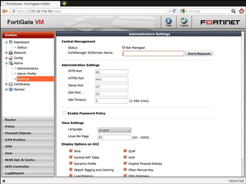
Figure 3.2 Controlling Administrative Access
You can also make this change via the CLI:
FGT (global) # set admin-port <integer> ← the port for HTTP access
FGT (global) # set admin-sport <integer> ← the port for HTTPS access
FGT (global) # set admin-ssh-port <integer> ← the port for SSH access
FGT (global) # set admin-telnet-port <integer> ← the port for telnet access
You may also need to change the administrative port if you want to have the FortiGate provide a port-forwarded config that uses the FortiGate’s actual IP address. For example, you wish to provide access to a secure web server on an internal network on the de facto standard port of TCP/443, if you leave HTTPS administrative access enabled on the interface connected to the Internet and don’t change the port then when an external user attempts to connect to the FortiGate Internet IP address on TCP/443 the user will receive the FortiGate WebUI login prompt instead of the desired web page from the internal web server.
In addition to controlling the port and protocol by which you can access the WebUI and CLI, you can also limit access at the IP level for each of the administrative accounts. These are known as the Trusted Hosts settings. Using the WebUI, navigate to System → Admin → Administrators → Trusted Hosts. If you are running FortiOS 4.3 you’ll need to select the checkbox labeled “Restrict this Admin Login from Trusted Hosts Only” before you will be able to configure them. If you are using a remote authentication service such as RADIUS, LDAP, or TACACS+ you will need to ensure that the set of trusted hosts for the administrative account covers all users that will be logging in via that method. Remember that if you have administrators logging in from home, they might have dynamically assigned IP addresses from their ISPs. If this is the case, and their external IP address changes, they may be locked out from administrating the device. You can work around this issue by only allowing access to the administrative functions from a VPN range or from statically assigned internal systems.
Tip
Login Banner Support
It’s normally considered a best practice to warn someone when they are attempting to access a secure system. In some legal jurisdictions, this is required, as otherwise people can claim ignorance that what they are doing is illegal.
Typically this is performed via some type of banner. FortiOS supports access banners for both CLI and WebUI access. You have full control over the content of these banners; they are part of the Replacement Messages configuration at System → Config → Replacement Message → Administration → Login Disclaimer. Once you have messages that you are satisfied with, you will need to enable this from the CLI.
The access banner is only displayed after you have successfully supplied a valid set of administrative credentials.
FortiOS Default Behavior to Non-Service Ports
Once upon a time, before security of networked equipment became a concern, there was a protocol known as ident3 that was intended to associate a username with a port. A number of legacy applications (and newer ones built on top of these legacy apps) still make an attempt to use this protocol. If the protocol is unavailable, there may be a long timeout and as a result most modern systems return a TCP RST packet to any attempts to connect to this service. This terminates the connection on the system that sent the original ident packet, so it doesn’t have to wait for the request to time out. This is also the default behavior for FortiOS. However, this is another tradeoff. Itspeeds up the dropping of connections that would not be useful anyway, but it also leaks information about the system. This is usually useful to an attacker during a probe or fingerprinting phase. You can optionally configure FortiOS to not send a TCP RST packet when a connection attempt is made, making it harder to determine the network devices in use. This is configured on a per-interface basis, so it would be most applicable on your external interfaces.
The behavior of the FortiGate for connections to any other IP/port combination for an IP Address configured on the FGT will depend on the FortiGate configuration, such things as the combination of administrative access and trusted hosts, or a Virtual IP associated with a firewall policy.
Network Time Protocol (NTP)4
If you will never need to use the log information generated by the FortiGate for legal or HR purposes, it is essential to ensure that the local clock is accurate. This is also essential if you plan to use a two-factor solution, as this will help to avoid problems with clock skew between the FortiGates and the tokens. Time synchronization also makes it much easier to analyze the timeline of an event if the clocks on all the systems involved are synchronized.
You can configure the system time and time zone manually from the Web UI dashboard System Information widget. You also configure an NTP server here, so the FortiGate can pull it’s time from a trusted source. Fortinet supplies pool.ntp.org as a default which should be fine for most uses. However, if your company runs an internal NTP server, it may be more appropriate to use that. While the Web UI allows you specify only a single NTP server, FortiOS actually supports the configuration of multiple servers through the CLI. Configuration of time servers based on the NTPv3 protocol is also available from the CLI, this version of the protocol requires an authentication string for access, so it is disabled by default and is normally only used when connecting to an internal NTP server.
Specifying the Source IP Address for FortiOS Originated Traffic
A FortiGate has many interfaces and, therefore, can have many source IP addresses. This can create problems in some situations. Consider a case where a large organization is using IPSec for site-to-site communication. In an environment like this, there could be multiple logging servers located at various points throughout the network. By default, when the FortiGate sends a message to local log server, it will use the IP address of the interface nearest the server. However, this means that the same device shows up in the logs under multiple IP addresses. This can make for difficulty when correlating log events. Similarly, if you use remote authentication (RADIUS, TACACS+, or LDAP), there often are hard limits on which IP addresses can request access. This provides protection to the authentication server, but means that every time an interface on the FortiGate is altered, the authentication configuration must also be changed or risk being locked out.
For most of the traffic that originates from the FortiOS, it is now possible to specify the source IP address that the device will masquerade as. You can specify any address you want, typically though, the IP address of the loopback or internal interface is used. This option is only available from the CLI and is configured within the specific service that you wish to masquerade, such as DNS, NTP, or logging. As of this writing, all traffic that originates from FortiOS can have the source IP changed except for sflow collectors and SNMP traps.
Dealing with Administrative Operations
Once deployed, the FortiGate becomes a critical part of your security infrastructure. Of course as a prudent administrator you need to be able to cope with a system failure. To be prepared, you should periodically back up the FortiGate configuration, understand how to upgrade the firmware, and know how to quickly get a replacement unit up and running.
Performing Backups
Since the system configuration may contain confidential information, only administrative accounts with sufficient privileges (such as the superadmin) are allowed to perform backup operations. Backups can be initiated from either the WebUI or the CLI. When performing the backup from the CLI, you can save the configuration in many places: on a TFTP server, an FTP server, a locally installed USB memory device or, if available, a FortiManager (see Figure 3.3).
| Method | CLI Command | Comments |
| TFTP | exec backup [config | full-config] tftp <ip address> <filename. | |
| FTP | exec backup [config | full-config] ftp <ip address> <filename> <username> <password> | |
| USB | exec backup config usb <filename>exec backup full-config usb <filename> | The file referred to by <filename> must be on the first partition of the USB memory stick and this partition must be formatted as FAT32 |
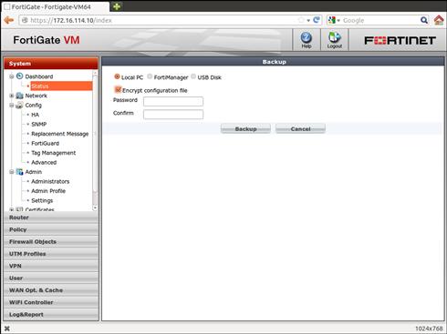
Figure 3.3 Performing Backkups
If you are using any type of certificate-based service on the FortiGate (IPSec/SSL-VPN tunnels using certificates for authentication, certificate-based user authentication, or any of the SSL inspection services), you will want to provide a backup password. The SSL Certificates stored on the FortiGate are only backed up when a password is provided. This way, there is reduced risk of losing control of the private keys, which could allow an attacker to intercept traffic the same way the FortiGate can. Needless to say, it is critical that you know the password to restore the configuration. There is no way to recover any information from password-protected backup file if that password is not known.
As of FortiOS 4.3 it is also possible for a VDOM Administrator to back up the configuration for just their VDOM(s). This works exactly the same as the methods described above, except that the backup only contains information for that particular VDOM.
Restoring the Configuration
Restoring a configuration is one of the few operations that requires the FortiGate to reboot. The process will replace any current configuration information on the FortiGate, including network configuration and administrative accounts. Thus, if you have changed your administrative access since the backup was performed (disabled HTTP, changed the SSH port, etc.), you will have to access the system the old way after the restore is complete. Be sure to check all of your settings after a restore to ensure that you don’t inadvertently lose hardening configuration.
You can restore a configuration using all of the same methods mentioned for performing a backup. If a password was used to backup the configuration, you will need to provide the correct password for the restore to be successful.
The restore process also checks the FortiOS version and model number used when the backup was originally performed. If they don’t match, FortiOS will refuse to restore the configuration. This avoids unexpected results, as there are occasionally CLI config command changes between FortiOS versions. When restoring a backup from a FortiOS version that is more recent than the version of FortiOS currently running, the backup may contain configuration statements that are inaccurate, invalid, or simply unsupported.
It is possible however, if necessary, to restore a configuration backed up from one version of FortiOS to a system running a different version of FortiOS, or even to restore a backup from one FortiGate model to an unrelated FortiGate model. This often occurs during an upgrade.
If you need to restore perhaps a backup made a while ago, when your FortiGate was running a different version of FortiOS, it is best to go through the downgrade/upgrade process, downgrading to the version of firmware from which the backup was made, then upgrading to the desired release following the process in the Release Notes for that version. However, if this is undesirable for some reason, you can manually edit a copy of the configuration backup and change the first line in the file to reflect the version of FortiOS that you are currently running. If the backup was performed using a password, then this method will not work, as the backup will be encrypted and not editable.
The first line of a configuration backup should contain a line that looks something like this:
You will need to change the firmware version information to match that of the current firmware. The simplest way to get this line correct is to perform a backup from the current firmware running on your FortiGate and then copy that first line over the first line in the configuration file you wish to restore. If you do not have access to the FortiGate to perform the restore, you will have to edit it manually. To do this, you must know the build number and the date code that follows, so in the above example, the “build315-110330” text is the complete version information.
If you are doing the restore, errors will be logged to the console. Follow the instructions in the “Multiple Image Support” section earlier in this chapter to connect. If there are any issues interpreting the configuration file, they will be output on the console, or if not of a critical nature they will be logged to a logfile and a message similar to the following will appear on the console
“Configuration errors found, please review the output of diag debug config-error-log read”
If you don’t have the option to view the console output during the restore, then you should definitely review the output from the above command at your earliest opportunity. This will highlight any configuration statements that could not be correctly applied to the currently running configuration.
If you are attempting to restore a configuration from one model FortiGate onto another model FortiGate, even if it’s the same version, you will need to make sure that the configuration is modified to reflect the physical characteristics of the target model. The most common changes required are interface names. Some of the entry-level models have interfaces named things like: wan1, wan2, internal, DMZ, etc. While other models have simply port1, port2, port3, port4, etc. Luckily, since the configuration is a text file, this is normally a simply search and replace exercise. Once you’ve looked after all the physical items, you’ll also need to modify the configuration file’s first line to reflect the new model. The above example was for a Fortigate 5001A, if we are attempting to install that config to a FortiGate 5001B as part of an upgrade, then the first line needs to become:
Note the only change was to the model information (FG5A01 became FG5B01). The rest of the line remains the same since, in this case, the new FortiGate 5001B will be running the same version FortiOS.
Upgrading/Restoring Firmware
It’s almost inevitable that at some point in your time with the FortiGate device, you will need to change the firmware image stored on the FortiGate. This could be to recover a failed unit or to upgrade/downgrade the firmware on a currently operating unit.
If the FortiGate is operating and you know the credentials for an administrative account with sufficient privileges, you can restore a firmware image from either the WebUI or the CLI. If the FortiGate is non-operational (powers up and loads the BIOS but cannot load the firmware from flash), or you no longer have valid administrative credentials, you can install a firmware image from the FortiGate BIOS.
To restore a firmware image from the WebUI, simply navigate to the System Information widget on the System Dashboard, select the restore option, and locate the file on your local PC.
When restoring a firmware image from the CLI, you can select from multiple different methods for transferring the firmware image to the device: TFTP, FTP, USB, FortiGuard and, if available, from a FortiManager.
Finally, you can restore a firmware image to an operating FortiGate device by power-cycling the FortiGate with a USB memory device installed. For this to work correctly, you will first need to copy an appropriate firmware image (obtained from the Fortinet Support website, http://support.fortinet.com) to the USB memory device and save it as a file named “image.out” in the root directory of the first partition (which must be formatted as whether FAT16 or FAT32) of the USB memory device.
When the FortiGate boots, the original firmware image will load, but during the initialization phase it will check to see if there is a USB memory device present. If the first file system contains a file called image.out, this file is then copied into RAM, the checksum verified, and the platform and version IDs checked. If all of these checks are valid, then the new image is copied to either the alternate boot partition (for devices with multiple boot partitions) or the primary boot partition (replacing the current firmware image). Once the copy completes, the FortiGate will automatically reboot to load the new firmware image. If the USB memory device is still installed after the reboot, the image won’t be reinstalled as the firmware version on the USB memory device will match the version that just booted.
If your FortiGate device is no longer able to boot the firmware image stored in flash memory, your only recourse is to install a new firmware image from the systems BIOS. This operation also overwrites the unit’s configuration file and is one method of recovering a unit for which you do not know the administrative credentials. This method requires that you have physical access to the FortiGate to connect to the console, and a computer running a TFTP server that can be directly connected to the FortiGate. The ethernet interface that you will need to connect to the TFTP server varies from model to model, but is typically either the port1 or internal interface.
Connect to the FortiGate’s serial console port using the Fortinet supplied console cable, your terminal emulator should be configured for 9600 baud, no parity, 8 data bits, and one stop bit, commonly known as 9600 N81.(see Figure 3.4)
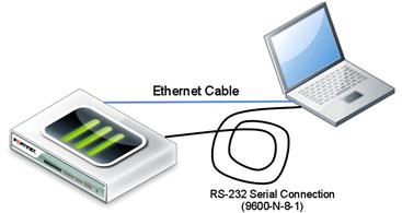
Figure 3.4 Connections Required for Firmware Installation via Console Port
Now, when you power up the FortiGate you should see output similar to the following from the console port:
Serial number:FG300A2904500319
CPU(00:00000f29 bfebfbff): Do MP initialization
Allocating PCI resources...Done.
Enabling PCI resources...Done.
Boot up, boot device capacity: 61MB.
The only important piece of information in the output at this time is the prompt to “press any key to enter menu”, when you do so a very simple text menu will be displayed. This prompt only appears for approximately five seconds, if you don’t press a key soon enough the FortiGate will continue the boot process, so power-off and try again.
[G]: Get firmware image from TFTP server.
[B]: Boot with backup firmware and set as default.
[C]: Configuration and information.
One of the most common reasons for a FortiGate to no longer boot from its flash storage devices is that these memory chips only have a limited number of read-write cycles. Sometimes very minor manufacturing flaws result in failure, though for most systems this is beyond the expected lifecycle. Due to this, when doing a manual recovery, it’s always a good idea to format the flash storage device. This ensures that any sectors that have gone bad will not be used for data storage. To format, select the “F” option from the menu. This will only take a very few seconds to complete.
At this point, the system will no longer have a firmware image or configuration, and so will be unable to participate as a network filter. The only method for getting a firmware image onto the system at this point is via the BIOS and a local Ethernet connection.
To upload the desired firmware image to the FortiGate via TFTP, select the “G” option. This option will prompt you for the TFTP server IP address, the IP Address to assign to the FortiGate’s interface and the name of the file to download from the TFTP server. As the device no longer does routing, there is no option to enter a default gateway. Thus, the system that is running the TFTP server needs to be either directly connected to the FortiGate or be on the same Layer 3 subnet.
Enter TFTP server address [192.168.1.168]:
Enter local address [192.168.1.188]:
Enter firmware image file name [image.out]: FGT_300A-v400-build0482-FORTINET.out
Total 20941933 bytes data downloaded.
Verifying the integrity of the firmware image.
Save as Default firmware/Backup firmware/Run image without saving:[D/B/R]?
Programming the boot device now.
The exact output on your FortiGate appliance may differ slightly from the above, depending on the exact BIOS and model, but the steps remain the same. The above output is from a system that supports two firmware partitions, so we are prompted for the partition in which to install the image. If you have formatted the flash as suggested above, then it doesn’t matter which partition you choose (they’re both empty) so you might as well choose the Default (also called Primary). If you have not formatted the flash, then “Default” refers to the partition already marked as bootable. This could be either the Primary or Secondary flash partition. If your system is an older one that does not support multiple firmware partitions, then you are prompted to either write the image to flash or directly run the image.
Password Recovery
If you like many users there will, unfortunately, come a time when you will be unable to login to and administer a device. There are many reasons that this could occur: the remote authentication system is unreachable, your credentials are incorrect, you don’t have the credentials, or you’ve restored a configuration and do not know what the restore reset the access credentials to.
There are two methods available for performing a password recovery. The first method is described above. Installing a firmware image from the BIOS overwrites everything in the partition, including the configuration, and therefore all the authentication details. Of course this means you have also lost all of the rest of the configuration as well.
If you need to recover the administrative credentials without losing the configuration, you must have physical access to the FortiGate. To perform the password recovery process, follow these steps:
1. Connect to the console port and make sure that you have access by pressing [Enter] a few times to get a system prompt.
2. Power the FortiGate off. This will interrupt any traffic passing through the FortiGate, so plan accordingly.
3. Power the FortiGate back on.
4. When you see the BIOS in the console, get a copy of the serial number, either by using copy/paste or writing it down.
5. Once the login prompt appears, login using a special account “maintainer”.
6. The password for this account will be the concatenation of “bcpb” and the systems serial number. Thus, if your serial number was “434522”, the password will be “bcpb434522”.
7. You only have 30 s from the time the login prompt appears to enter the correct username and password information, after that the account is automatically disabled. Thus, it is wise to use copy/paste on your system.
For most deployments, the fact that you need physical access to the FortiGate should avoid any abuse of this option. However, as of FortiOS 4.3, it is possible to completely disable this feature. The following parameters would disable the password recovery:
Be aware, though, that if this is done, resetting the administrative credentials will require a complete reinstallation of firmware from the BIOS.
Automatic FortiAP Firmware Updates from FortiGate
To simplify the operation and maintenance of a Fortinet-powered secure wireless infrastructure, you can have the distributed FortiAP update their own firmware images directly from the system acting as the Wireless Access Controller. To enable this, you need first to add the FortiAP firmware to the FortiGate that is the Access Controller. You do this via TFTP or FTP in a similar manner as applying a firmware update.
FGT # exec wireless-controller upload-wtp-image tftp <image name> <server IP>
FGT # exec wireless-controller upload-wtp-image ftp <image_name> <server IP><:port> <username> <password>
You can upload multiple firmware images to the FortiGate, but only one per FortiAP model.
To view the current images on the Access Controller, you must use the “wireless-controller list-wtp-image” command.
By default, when the FortiAP reboots, it will automatically update the firmware image. If you want to disable this capability, you will need to update the configuration for the FortiAP from the CLI.
Finally, by default when you access the FortiAP from the console port, there is no password defined. This is typically not a problem, as they aren’t very easy to physically access. However, it is still recommended that you change the password. At this time, this can only be done from the CLI.
Enabling VDOMS
One of the nice implementation features of FortiGate’s VDOMs is that you don’t need to decide at installation time whether or not you will use them. They can easily be enabled at a later date. You can even enable VDOMs while the firewall is running without affecting traffic. The only impact is that administrators be logged out of the administrative interfaces when VDOMs are enabled.
When VDOMs are enabled, all initial security-related configurations are automatically moved to the default VDOM, which is named “root”. This VDOM is automatically created when VDOM’s are enabled and cannot be deleted. All system-level (cross-VDOM) configurations are performed outside of the VDOMs in what is referred to as Global mode.
The simplest way to enable VDOMs is from the WebUI. Navigate to the System → Dashboard page and look at the “System Information” widget. This widget should indicate whether VDOMs are enabled. If they are not yet enabled, clicking on the “Enable” link will present a dialog warning the Administrator that this action will log them out. Selecting “OK” will trigger the enable process and log you out. When you log back into the WebUI, you will immediately notice that there are significantly fewer options in the left-hand menu. The bottom of this menu is a selector that allows you to toggle between “Global” and “root”. All of the configuration that you had on the FortiGate previously will now be found in the “root” VDOM.
For administrators considering a complicated configuration utilizing multiple VDOMs, it is recommended that you use the default root VDOM for Out-of-Band management. This VDOM would contain a single interface so it would be unable to function as a firewall. However, it would provide a good way to access the system. All actual user traffic would be via interfaces tied to other VDOMs.