Chapter 9
Managing Your Security Configurations with FortiManager
Information in this chapter:
• Top Down vs. Bottom Up Management
• Creating Administrative Domains
• Device Level Management & Configuration
• Installing Policy and Device Configurations
FortiManager is the centralized management console for maintaining Fortinet device deployments, which can be deployed in an appliance form factor or as a Virtual Machine (VM). This technology scales to potentially thousands of devices depending on the size of the FortiManager console deployed. The centralized console aids an organization by allowing granular controls and administrative privileges. It allows for template-based configurations of large deployments with configuration revision control capabilities and the ability to host the signature updates and web database queries as an extension of the FortiGuard Distribution Network for the managed devices among other features all through a single Web UI.
Upon first logging into the FortiManager an administrator will find multiple console tabs across the top of the web interface. The “System Settings” console is where the FortiManager device itself will be configured along with settings that affect options available in the other tabs. The “Device Manager” console is the location where you will maintain all managed devices and where device-specific configuration will occur. The “Policy & Objects” tab is the primary security console where all policies are managed and the object database is stored. The last tab presented is the “Real-Time Monitor” console where basic device monitoring can be configured and one can observe the status of the devices under management.
Later in this chapter we will also explore the “Administrative Domain” and the “Global Policy & Objects” tabs.
Being that the FortiManager could realistically be a stand-alone topic for its own book, we will provide an overview of each console while providing additional detail on points that will help an administrator begin using a FortiManager to maintain a large Fortinet deployment.
System Settings Console
The System Settings console contains four main sections, “General,” “Admin,” “FortiGuard Center,” and “Advanced.”
The first screen the administrator sees is the System Settings → General → Dashboard. Like the dashboard seen in the FortiOS device Web UI, this dashboard is also made up of multiple Widgets. The Widgets can be opened, closed, and positioned for each administrator logging into the platform. Like FortiOS, there are the System Resource and CLI widgets, but for the FortiManager arguably the two most important widgets are the System Information and License Information widgets.
The System Information widget provides your serial number, HA Status, and other basic information, but it is also the widget that allows us to verify and upgrade the FortiManager firmware, back up and restore the system configuration, as well as enable advanced features such as the use of Administrative Domains and the FortiConsole Software.
The License Information widget allows us to add to the features of the FortiManager by adding the license data to increase the number of administrative domains supported by the system, enabling the use of Global Policy & Objects and the Web Portal.
The System Settings → General → Network section gives you the ability to maintain the IP configurations for the interfaces on the system, modify the routing table, and apply the appropriate DNS server information to ensure you can communicate with the managed devices and the FortiGuard Distribution Network (FDN). In addition to the basic IP information applied to each interface, the administrator will also choose the interfaces on which to enable FortiGate and FortiClient updates to be served.
The System Settings Certificate and Local Log sections are exactly what one would expect. You can view and maintain the Local and CA Certificates in the Certificate section while in the Local Log section you can view the local event logs. The Diagnostic Tools section provides the user access to the ping and trace route utilities in the GUI without needing to navigate to the CLI.
The HA section allows you to configure the High-Availability (HA) Cluster Settings. FortiManager High Availability differs from the FortiGate implementation. With FortiManager you configure one primary and up to four secondary or backup units. So long as all units have IP connectivity, units in the HA cluster do not have geographic limitations. While all configuration and database information is automatically replicated between HA members, in the event of a loss to the master unit, you must manually promote one of the backup units to the role of master.
The Admin subsection of the System Settings tab allows you to create administrators and authenticate them locally or remotely via Radius, LDAP, or TACACS+. Regular user accounts, or non-“Super_User” accounts, can be restricted to specific Administrative Domains.
The administrator accounts are assigned a “Profile” which outlines the privileges allowed to that user. Privileges are allowed in a Read-Only or Read-Write mode and are provisioned based on the “Scope” of the Profile, either “Global” or “ADOM” (see Figure 9.1).
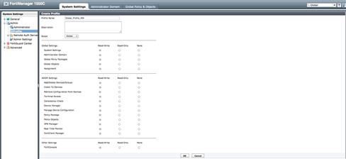
Figure 9.1 Admin Profile
Many of the features you will want to leverage when managing devices throughout the rest of the web interface are enabled in “Admin Settings.” Features such as IPv6 administration and the enabling of the Central NAT table will become useable throughout the web interface by selecting them here and applying changes. If you enable the use of administrative domains via the Dashboard Systems Information widget, you will also be able to enable the Global Policy & Objects features.
In some environments you will prefer that your Fortinet devices do not connect directly through the Internet to access the FortiGuard Distribution Network for updates. In this case, FortiManager can be configured to act as an extension of the FDN. The FortiManager will directly pull signatures and update the URL and SPAM databases in order to allow the security devices within the environment to then get their updates directly from the FortiManager.
By choosing your configuration options within the “FortiGuard Center” section, you can have the FortiManager download the update services for any FortiGate, FortiClient, FortiMail, and FortiAnalyzer that have the appropriate subscription services enabled. Understand, though, that the FortiManager will enforce the same limitations on downloads to devices without subscription services, as would the FortiGuard Distribution Network. In addition to service updates, the FortiManager can be configured to download the firmware for the managed devices to be used when scheduling firmware upgrades.
The “Advanced” section also supports “Meta Fields.” These data fields can be created to allow and/or require administrators to add additional information when manipulating system and security objects. By default, there are many optional Meta Fields, such as the Company/Organization, Country, Province/State, City, and Contact fields that are available when you create a new device. As an example, it is common to use a mandatory meta field when creating a firewall policy object where the field requires the administrator to include as a value, a reference number to a change order. This allows the auditing of rules created based on who created the change and under what authority the change was made and simplifies the change control process.
Administrative Domains
A FortiManager Administrative Domain (ADOM) is analogous to the Virtual Domain concept within the FortiGate. The use of ADOMs allows us to create separate logical environments in which we can maintain separate sets of devices. These devices may be physical (i.e. FortiGate appliances), virtual (i.e. FortiGate-VM), and/or logical (FortiGate Virtual Domains). Each administrative domain provides a separation of management based on geographic responsibilities, business unit partitioning, or any other reason one might need to maintain separate zones of responsibility. The number of ADOMs you can create is dependent on the FortiManager platform you have deployed, however, at the time of this writing, even the smallest FortiManager supports 10 ADOMs and larger units can support hundreds.
Top Down vs. Bottom Up Management
When creating an Administrative Domain you define one of the two modes in which you wish the ADOM to operate: “Normal” or “Backup.”
An ADOM in “Normal” mode operates, as most would expect when using most centralized management solution, with a “Top Down” structure enforced. In a Top Down management architecture, all device configurations are centrally maintained and then provisioned to the managed devices.
When a FortiGate is managed in a “Normal” mode ADOM, direct access to the devices is still supported. However, making changes at the device can cause synchronization conflicts with the FortiManager, which would need to be remedied as described later. If the managed devices are running FortiOS 4.3 or later, you will be warned when logging in that the device is centrally managed and that changes should be done via the FortiManager. The warning banner also provides you with the option to login into the system in a read-only mode, in a privileged (read and write) mode or to logout.
One of the advantages of a FortiManager over many other solutions is the ability to additionally support the “Backup” mode. This allows for a “Bottom Up” deployment where all configuration is performed at a device level, but the FortiManager Administrative Domain allowing for a “Bottom Up” deployment architecture. When managing device within a “Backup” mode ADOM, the administrators are able to continue operating in an environment where all configuration management is maintained at the device level. While no configuration provisioning is centrally maintained, the FortiManager can still be leveraged for revision control as a configuration repository, for script deployment, centralized firmware upgrades, FortiGuard service updates, and device monitoring.
Creating Administrative Domains
Before you can create multiple ADOMs to suit their deployment requirements, you must first enable Administrative Domains.
To enable ADOMs through the Web UI, simply go to the “System Settings” tab and navigate to the “System Settings → General → Dashboard.” Once at the dashboard, locate the “System Information” widget and select the “Enable” link on the row for “Administrative Domain.” After confirming that you want to enable ADOMs, you will be required to log back into the FortiManager.
Upon re-authenticating, the administrator will encounter a slightly different tab layout. Gone will be the “Device Manager” and “Policy & Objects” tabs and instead we will now see the “Administrator Domain” tab. In this new tab, we are able to create, edit, and delete administrative domains for our administrative needs.
From the ADOM tab we are able to view the ADOMs created on the FortiManager as well as the device statuses within each ADOM. If this is the first time accessing the ADOM tab, only the default “root” ADOM will be visible. In order to create additional ADOMs, we simply select the “Create New” button or right click and select the option “New.” Upon doing so we will be presented with the ADOM creation screen (see Figure 9.2).
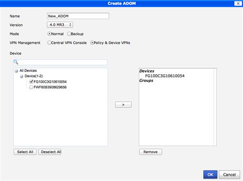
Figure 9.2 ADOM Creation
Start by giving the new ADOM a name and “Version.” The Version selected must correlate to the firmware revision of the devices to be managed. As of this writing, the supported versions are 4.0 MR2 and 4.0 MR3. The “Mode” of operation will either be left as “Normal” or changed to “Backup.”
If you choose to continue to create the ADOM in Normal mode, you will also need to select the “VPN Management” options. The choices are “Central VPN Console” and “Policy & Device,” both covered in some detail later. Last, you will have the option to select from devices already being managed and include them into the ADOM. You can select none, one, or many devices depending on the requirements. However, bear in mind that any devices moved into this new ADOM will no longer be accessible in their previous.
After ADOM creation, you can always use the right click option to “Edit” the ADOM and change any of the configuration options. To enter an ADOM and manage your device, you can right click over the desired ADOM and select “Enter ADOM.” Then hover your mouse over your intended ADOM and select the “Enter” button that appears or use the drop down menu in the top right of the Web UI.
Once in the ADOM, you will find your “Device Manager” and “Policy & Objects” tabs unique to the ADOM. Each ADOM maintains its own device, policy, and objects databases, allowing for unique configurations of the devices within each ADOM.
Device Manager
Within each Administrative Domain you will find the “Device Manager.” The Device Manager is the tool used to add devices to be managed and to maintain all of the device-specific configurations.
“Add Device” Wizard
There are multiple approaches for importing devices into the FortiManager. The first of the two approaches we will cover is the “Add Device” wizard. This wizard will walk you through discovering your device settings, importing policies and objects, and exporting them to the security console “Policy and Object” tab. It will also walk you through the process of mapping the device interfaces to the security console’s Zones.
Selecting the “Add Device” button toward the top of the window will launch the import wizard and walk you through the steps to import your device.
The first screen is where we input the IP Address, User Name, and Password information for the device we want to add to the manager. The User Name and Password must be that of a privileged administrator on the device we intend to import. FortiManager will use this account to read and write directly to the managed device when we deploy configurations, execute CLI scripts as well as manage firmware upgrades. If there is a concern about the level of privilege for the specific administrative account, that account can be locked down to the IP addresses of the FortiManager system using the trusted host option on the device.
You also have the option to add a modeled device if you want to prepare to manage a system that is not yet in production. When adding the modeled device, you will provide the IP Address, User Name, and Password for the device to be managed. However, unlike when adding a live device, the wizard will not walk you through the importation of objects and policy configuration as those settings would not yet exist.
By selecting “next,” the FortiManager will attempt to login and query the device using the account provided. Assuming good IP connectivity exists, allowing TCP port 514 access to the device, the account has the correct access right to the device and the device is configured to allow FortiManager administration on the interface to which you are attempting to connect, the device will be discovered and you will be provided a summary. This summary will include the IP Address, Admin User, Device Model, Firmware Version, Serial Number, and the High Availability Mode of the device. If all the information is what as expected, you can select “next” to move forward. If there was an error, you can go “Back” and correct your mistakes.
The next step allows you to choose a name and description for the device. The default value will be what is configured on the device, though if that is not unique enterprise-wide, you may wish to change it. During this step, you can also choose to include this device into one of the defined groups. You will also be able to add other administrative information such as the location and a primary contact.
As you move to the next step in the wizard, the FortiManager will retrieve all the device’s configuration settings and load them into the FortiManager device database. Once added, the FortiManager will walk you through mapping the device’s interfaces to Zones, importing the security objects into the ADOM’s Object Database, and copying the policies into a Policy Package. If the device being imported is configured with multiple VDOMs, the wizard will walk you through these processes for each individual VDOM.
During the Zone mapping of the device’s physical interfaces, the FortiManager will present you with those interfaces that have policies applied and offer to create Zones with names that match the interface names. At this point, you can choose to accept the new Zone names, to map the interfaces to a new Zone, or map them to Zones that have already been created in the Policy and Object console. If you wish to select an existing Zone, you can begin typing the name of that Zone. If you are not positive of the Zone name you wish to select, character match-based suggestions will be presented. However, be aware that these suggestions are case sensitive.
The last option to select is whether or not you want the FortiManager to automatically map all of the interfaces to Zones with names matching those of the interfaces themselves, but without policies applied. This is often useful for devices with many interfaces.
The next steps walk through the process of importing the policy configuration from the device into a New Policy Package where you can select the name of the package as well as the package folder in which to store it. You also have the option to import all of the device’s policies or choose to select specific rules to be imported. Understand though that everything set in the Policy Package, the next time you push to the device, will be the policy set on the device. If you do choose to leave policies out of the import process, expect those policies to vanish from the device when the package is modified and redeployed to the platform.
During the import process, you will be able to review the object being imported, view any duplicates that will not be imported, and be presented the option to choose which object to keep to resolve conflicts with an already-existing object of the same name in the database. Once this process is complete, you will see a summary created as well as the option download and view the “Import Report.” The import report provides us a more detailed summary of the zones, policies, and object imported.
Adding Multiple Devices
The second method to discuss is only available if you have enabled the “Show Add Multiple Button” in System Settings → Admin Settings. This provides the ability to add multiple devices to an administrative domain in a single action. By navigating to the “All FortiGate” folder within the Device Manager tab, you can select the “Add Multiple” button and be presented with a new screen. By providing the Name, Device Type, IP Address, Admin User, and Password for each device you intend to add, the FortiManager will query each and import the configuration into the database (see Figure 9.3).

Figure 9.3 Adding Multiple Devices
This process does not include an automatic walk through to assist with importing the objects and policies into the FortiManager’s Policy & Objects database. This can be helpful when adding multiple devices to be managed by the same policy package.
If you must install the objects and policies from any of the devices, the process is pretty straightforward. After you select the “All FortiGate” folder, right click on the device you wish to import and select “Import Policy.” This will walk you through the Zone Map, Object, and Policy portion of the Add Device wizard and, following the same process outlined earlier, will import the information into the Policy & Objects database. For each additional device to import, you will repeat this process (see Figure 9.4).
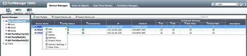
Figure 9.4 Policy Importing
Device Groups
With many devices to manage, the creation of Device Groups will help to organize and manage the environment. Groups not only allow us a way to view our device-based organization relationships, but also allow us to execute actions such as configuration and firmware deployments at the group level, thereby reducing the operational step to managing the environment. It is also possible to nest group to provide a potential hierarchy of management.
Select the “Add Group” button to create your Device Group. The “Add Device Group” window will appear, allowing you to name the group, select the group OS type, and the device and/or groups to be included in the new group.
Once your groups are created, they will allow you to monitor those devices in the group as well as allow you to deploy scripts and firmware to the devices in the group without requiring you to perform those tasks on a device-by-device basis (see Figure 9.5).
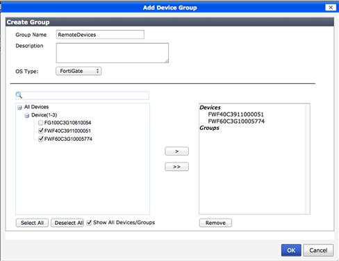
Figure 9.5 Adding Device Group
Device Level Management & Configuration
The Device Manager allows us to monitor licensing, firmware revision, and configuration status of each device on the system. You can also manage the configuration revisions of each device, view the changes deployed or planned to be deployed and, if required, revert to a previous revision.
With your devices are added and your device groups are created, you can maintain all of the system-level configurations required to manage your environment. Selecting a device to manage will offer a layout for the configuration workflow similar to that seen in the FortiOS Web UI. One difference to remember is that any changes made are not performed immediately. Instead, they are staged and installed at a later time using the “Install” wizard (see Figure 9.6).
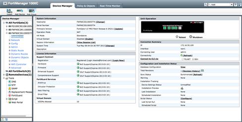
Figure 9.6 A Device Dashboard
While the majority of the device configuration is nearly identical to that of the native devices, there are some additional configurations to be maintained with FortiManager. The first is the “Zone Map.” The Zone Map associates each device’s physical interfaces with the logical representation of source and destination zones used in the Policy & Objects section. If you have used the “Install” wizard, the FortiManager will have a mapping for each interface. If, however, you did not use the wizard or desire to change the mapping, navigate to the device “Network” → “Zone Map” section and right click on a row. You will be able to add to or edit the existing interface mapped to that zone. If you must map an interface to a new, not displayed, zone, select “Show Unmapped Zones” in the upper left portion of the right pane and all available zones will be displayed. Then, as before, you may right click on the row containing the zone to add an association (see Figure 9.7).
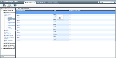
Figure 9.7 Zone Mapping
The other main area that differs from the FortiOS-based workflow is the “Dynamic Objects” configuration. Security objects used during policy creation are maintained in the object database in the Policy & Objects section. There are times when an object may use a global name, but must have locally unique value. A simple example would be an environment with a thousand distributed locations where each device is managed by the same policy set… an ability of the FortiManager to be explored shortly. Each of these locations has a unique range of addresses that require the same policy applied. Instead of needing to maintain one thousand unique objects in the policy set, you can create a single address in your database and map that to its unique value at the device level through “Dynamic Object” → “Address.”
To accomplish this, an object is defined in the object database. Once that object is created, the administrator will create a new dynamic object at the device level, mapping the unique value to the object name in the object database. While there are additional steps needed to map the device level dynamic objects, it will save significant time to maintain the security posture of potentially thousands of devices. During the import of a device using the “Add Device” wizard, if an object exists on the device with the identical name of an existing object in the object database that local object will automatically be mapped to a dynamic object on the FortiManager.
The types of Dynamic Objects supported as of this writing are addresses, virtual IPs, IP Pools, Local Certificates, and policy-based VPN Tunnels.
If the administrator has selected “Show Device Manager Tools” in the administrator area, you will also have access to advanced tools such as the Script and Web Portal Managers. While we will not be able to cover these topics in detail, these tools can be powerful.
The scripting tools allow an administrator to create CLI and/or TCL-based scripts to be deployed to the devices being managed. A simple example of this could be the need to change the “admin” password on all devices at once. More information on this topic can be found in the “FortiManager Administrator’s Guide” found at http://docs.fortinet.com/fmgr40.html.
The Web Portal allows an administrator to create unique web portal access to sub-administrators, potential users, with configuration capabilities limited to very specific object types. This way, you could delegate the responsibility of managing URL filtering to someone in HR without needing to worry about them causing problems with firewall or routing.
Policy & Objects
To be consistent with the rest of the FortiManager web interface, the “Policy & Objects” tab is arranged into left and right panes of focus. Starting in the left pane you find the “Policy” tree, the “Objects” tree, and, depending on the system configuration, you may also be presented the “VPN Console.”
Policy Package Management
The “Policy” tree is where you will maintain and organize the policy packages used to define the firewall security configurations that are to be installed down to the managed devices. Policy packages can be assigned to a single or multiple devices based on the administrator’s requirements. This allows for a significant reduction in the workload required to maintain the security posture of potentially thousands of devices.
The first time entering the “Policy & Objects” tab, the administrator will find the policy package named “default.” If the administrator has already used the “Device Manager,” there may also be additional policy packages available. Use of the installation wizard was covered in detail during the “Device Manager” section above.
To create a new policy package, simply right click on “Policy” in the left pane and select “New,” “Policy Package.” This selection will present the administrator with the “Create New Policy Package” pop-up. When creating a new policy package, you are required to provide a unique name for the new package. When creating it, you also have the option to clone an existing policy package and/or select the installation target or targets to which the package will be applied (see Figure 9.8).
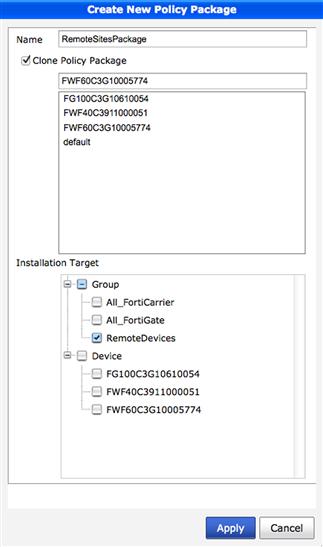
Figure 9.8 Creating New Policy Package
The cloning option allows you to create a new package based off of an existing template, to create a copy or backup of an existing package that you plan to manipulate, or for any other reason to duplicate an existing package. Once you select “Clone Policy Package,” a list of the available packages is displayed. Simply select the presented package you intend to clone.
The last decision to be made when creating a new policy package is to determine the installation target or targets for the new package. Targets can include a single managed device, multiple managed devices, one or more device groups, or any combination of devices and groups, including none. Selecting “apply” to complete package creation without selecting at least one device to install the package on will result in a warning that no targets have been selected. If you did not select a target in error, simply select cancel when warned and choose your targets and reapply. It is, however, perfectly acceptable to create a package that does not contain any active targets. Installation targets can always be selected after package creation by right clicking on the package name and selecting “Edit.” A screen similar to the package creation screen will be presented, allowing the administrator to select additional devices and/or remove existing targets.
While a single policy package can be assigned to multiple devices, deploying multiple policy packages to a single device may not have the desired or expected results. While it is possible to have more than one package configured for the same target, the intent is not to have multiple packages applied to the device at the same time. During the deployment process, each package overwrites the previous. So, installing multiple policy packages to a device in sequence will have the result of only the last package taking effect. If an administrator was to install multiple policy packages to a device or group of devices in sequence, the last policy package applied will define the rule set on the device or devices overwriting the rule sets applied in the previous installations. Without the understanding that applying multiple packages does not have a cumulative effect on the security posture will create a situation where you do not have the setting you want on the device and potentially cause a degraded security posture.
If there is a requirement to have a layered rule set, a simple example being a corporate security policy that needs to be applied to all Firewalls regardless of the local administrators rule base, this is possible with FortiManager. We will cover this topic by describing the use “Global Policy Packages” later in this chapter.
If an administrator finds they need to manage many policy packages, it may be convenient to organize the packages into folders. Similar to creating a new package, one would again right click on “Policy” in the left pane and then select “New” → “Folder,” provide a name for the new folder, and select “OK.” In order to organize the policy packages into folders, simply left click on the package and drag that package into the folder desired. If the complexity is warranted, folders can be created and organized hierarchically.
As packages are intended to maintain the security policies to be deployed to the devices, individual policies are created similarly to how policies are created within the FortiGate Web UI. However, the Web UI of the FortiManager is much more flexible, as it allows you to copy, cut, and paste polices, as well as drag and drop policies for reordering. You are provided much more flexible search and “where used” capabilities and a context-sensitive right click function that will present different functions, based on the policy package you intend to manipulate (see Figure 9.9).
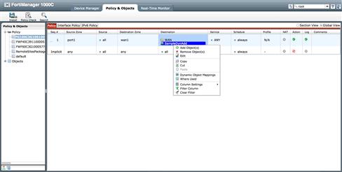
Figure 9.9 Policy rule GUI Options
Unlike a policy set on a device that references the interfaces and security objects of that device, policy packages can apply to a single device or many devices. To accomplish this, the packages will reference values from the domain’s Object database.
Managing Security Objects
Each Administrative Domain has a database for administrators to create the security objects needed to maintain their environment while avoiding name and value conflicts, as different ADOMs have their own database space.
As mentioned previously, the administrative workflow is nearly identical to that seen in the FortiOS Web UI. The key difference is that these objects will be applied across policy packages that affect the security posture of potentially thousands of devices. This greatly reduces the work required to tune the environment’s security.
Installing Policy and Device Configurations
When an administrator must deploy configuration changes to the managed device, they will want to verify them prior to deployment. First, an administrator may wish to leverage the “Policy Check” feature. This is only available if you have enabled it in the “Admin Setting” section. Policy Check runs a validation process against all the Policy Packages in the domain and will indicate conflicts, shadowed policies, duplicate objects, and candidates for optimizations (see Figure 9.10).
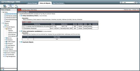
Figure 9.10 Policy Consistency Checks
After you are comfortable with your packages and are ready to deploy them, the “Install” wizard will walk you through the process. You will be prompted to install all pending changes including the Policy Package data or to just install the device level configurations. If you choose to deploy all pending changes, the wizard will allow the selection of which Policy Packages are to be deployed and to which of the targeted devices. During the wizard execution process, the interface to zone mappings will be validated, giving you an opportunity to preview the changes. After successful deployment, the FortiManager will save a new revision in the device’s revision history, assisting with future auditing (see Figure 9.11).
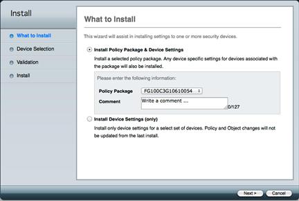
Figure 9.11 Installation Wizard
Global Policy & Objects
In some environments, there will be a need to have individual administrators responsible for their respective devices while still allowing a more senior administrator to override policies. The FortiManager allows this hierarchical approach to deploying policy through the use of “Global Policy & Objects.”
Like the other features on the device, Global Policy & Objects is a licensed feature that is enabled in Admin Settings. This workflow and configuration tasks are nearly identical to the workflow of tasks in the Policy & Objects section. The few differences between the workflows are detailed below.
First, the Global Packages consist of “Header” and “Footer” policies. While the policies are created and managed like those in a normal packager, in a Global Package, the Header Policies will be prepended to any Policy Package at the ADOM level. However, the Global Package is also assigned as the Footer Policies will be appended to the policy set in the local ADOM packages. This provides the ability to override the ADOM Packages with Header Policies and to use Footer Packages to add trailing rules prior to the implicit deny (see Figure 9.12).
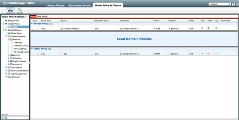
Figure 9.12 Global Policy
Like the ADOM “Install” wizard used to deploy changes to the managed devices, Global Policy & Objects are deployed to the Policy Packages in the ADOM using the “Assignment” wizard. When launching the Assignment Wizard you select the Global Package to be deployed and the ADOMs and/or Policy Packages within the ADOMs to which you will assign the Header and Footer Policies. New Header and Footer Policies are not deployed to the managed devices until you select to use the Install wizard in the appropriate ADOM (see Figure 9.13).
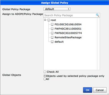
Figure 9.13 Global Policy Assignments
Finally, understand that to use Global Zones their names must match those of the ADOM zones to which they will be applied. If there are no matches, the assignment will fail. As of this writing, zone names do not “inherit,” so preplanning zone naming is important.
Managing Site-to-Site Distributed IPSec VPNs
Most people choose to use a centralized management console when they must maintain a large distributed IPSec VPN network. There are many complexities involved and these challenges tend to increase faster than the network does. To provide service at scale as these networks grow, the FortiManager provides two different methods for managing IPSec VPNs.
Policy and Device VPNs
The first, and default, method is known as “Policy and Device VPNs.” If you are required to utilize multiple ADOMs in managing your environment, it is also the default mode selected when creating each additional administrative domain.
With this approach, IPSec configuration is managed in the “Device Manager” tab. The Phase I and Phase II configurations are constructed and maintained on a device-by-device basis with a configuration workflow effectively identical to that seen in FortiOS. Because the IPSec configurations are maintained on an individual device basis, this mode of operation does not provide much economy of scale during the tunnel creation process. However, there are still many advantages in using the FortiManager to maintain devices security postures. You can leverage the common object database and policy packages to simplify the workflow required once the tunnels are established.
Preparing to Create the VPN
Once a network plan is in place, you will need to determine how you want to apply policy to the devices and tunnels. The decision process will include whether to leverage the simplicity of using a single policy package across multiple devices to reduce administrative overhead or if each device will require a unique policy package. In addition to determining how to best apply the policy packages, you must determine how to treat a device with multiple tunnels defined. Will each of the tunnels have a unique set of policies or will they share a common policy structure? If the tunnels will share the same security requirements, you can group them together, again reducing the maintenance overhead.
It is reasonable to see environments with many devices, each possibly with multiple tunnels defined, all managed with a single policy package and little forethought. This approach can be used to allow a simple network design to scale. However, be aware that the “heavy lifting” is required initially in the creation of the actual IPSec tunnels, accomplished device by device through the device manager.
To illustrate how a FortiManager assists with VPN management in the Policy and Device VPN mode, below is a simple Hub and spoke VPN network. We will now walk through the creation of both a Policy Mode VPN network as well as an Interface Mode VPN network. As you will see shortly, how you define the tunnels will determine how they are treated within by FortiManager (see Figure 9.14).
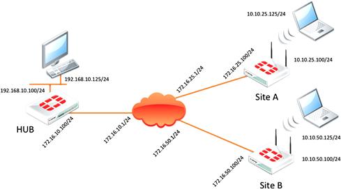
Figure 9.14 Lab Layout
Creating and Managing a Policy Mode VPN
In the simple case, the security posture for the Hub location will be maintained with a unique policy package. The package will allow traffic sourced from the internal protected segment (the 192.168.10.0/24 subnet) will access the remote protected segments of Sites A and B through the appropriate IPSec tunnel. Both Sites A and B will have identical security requirements, allowing traffic sourced from their local segments (10.10.25.0/24 and 10.10.50.0/24 respectively) back to the Hub’s internal protected segment and will be able to share a common policy package. Sharing the same package helps us reduce the management overhead of this type of distributed network and could allow us to grow far beyond the two remote sites in our example.
To create this VPN we will need to do six steps:
• Define the VPN Tunnel Dynamic Objects.
• Create the Firewall Address objects representing the protected segments.
• Configure the appropriate Policies in the Policy Packages.
• Construct the IPSec Tunnels.
• Define VPN Tunnel and Address Dynamic Objects for each device.
When creating the tunnels in Policy Mode, you are required to define VPN Tunnel Dynamic Objects to use when building Policy Packages. Within the Policy Packages, these dynamic objects allow you to select the appropriate tunnels for IPSec policies.
For each tunnel defined on a device you will need a unique Dynamic Object. In this example we have created three of these objects. “Tunnel-To-SiteA” and “Tunnel-To-SiteB” will be associated with tunnels on the Hub to the appropriate remote location. The object “Tunnel-To-Hub” will be associated at both Site A and B devices, representing the corresponding tunnels from each site back to the Hub. By using this one dynamic object for each remote location, we can create a single policy package across multiple remote sites. This approach can be applied across hundreds of sites. You will see how to apply these dynamic objects shortly (see Figure 9.15).
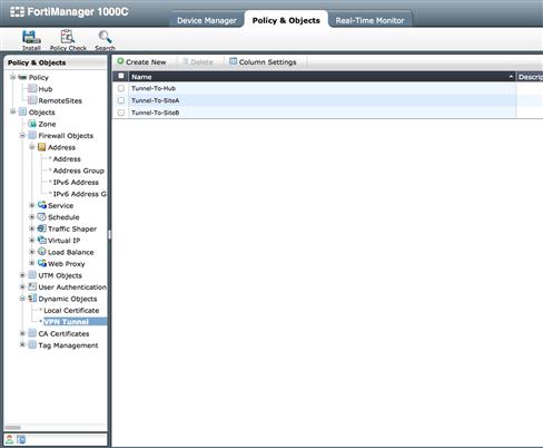
Figure 9.15 Policy Mode IPSec Dynamic Tunnel Objects
The next objects we must prepare are the Firewall Address objects used to define the protected subnets. We will use these to identify the traffic that must be secured. With the same workflow we covered earlier in this chapter, we create the Firewall Address objects “Hub-Internal” (192.168.10.0/24), “SiteA-Internal” (10.10.25.0/24), and “SiteB-Internal” (10.10.50.0/24) to be applied in our Policy Packages. While most networks require a more complex use of address objects to restrict or allow access more granularly, our example is kept straightforward to focus on the steps required to get the VPN up and operational (see Figure 9.16).

Figure 9.16 Policy Mode IPSec Address Objects
Now that our objects are defined, we can define the policies needed to define which traffic will be selected for transport over the VPN. In the Policy Package to be installed onto the Hub device, we must create policies that define the traffic associated with each tunnel on the device. The greater the number of tunnels, the more complex the Policy Package will need to become. In this package, we create one policy identifying traffic sourced from the Hub’s internal segment destined to Site A’s internal segment. This will transport through the tunnel between Hub and Site A. Similarly, we will create a second policy for traffic destined to Site B using the tunnel between it and the Hub (see Figure 9.17).
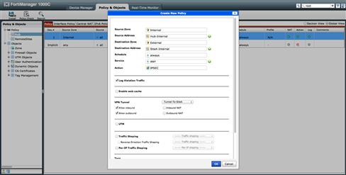
Figure 9.17 Policy Mode IPSec Local Device Encryption Policy
For the remote locations, we will leverage a single policy package across multiple devices and use them to define the traffic to be encrypted back to the Hub site. To accomplish this goal, we will use a very broad policy allowing “all” traffic destined to the protected segment of the Hub, “Hub-Internal,” sourced from the Internal zone of the remote locations to be sent to the “Tunnel-To-Hub” VPN Tunnel Dynamic Object (see Figure 9.18).
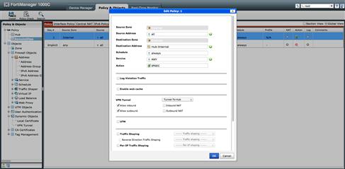
Figure 9.18 Policy Mode IPSec Remote Device Encryption Policy
At this point in the configuration, VPN Tunnel Dynamic Objects are used to define the tunnels in our policies. What may not be clear, though, is how these objects are associated with the actual tunnels, yet to be constructed.
As mentioned earlier, the actual creation of the tunnels is accomplished by navigating to the IPSec configuration section. At each device we will apply the appropriate Phase I and Phase II configuration parameters for the tunnels with the same workflow seen within FortiOS. As we are utilizing Policy Mode VPNs, it is important to NOT select “IPSec Interface Mode” during the Phase I creation (see Figure 9.19).
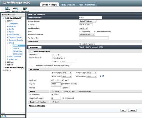
Figure 9.19 Policy Mode IPSec Phase 1 Settings
An additional item to verify is that our routing configurations contain the appropriate routes for the remote segments. Being Policy Mode, the routes will identify the interface to which we have bound the tunnels. In most networks the tunnels will be bound to the “External” interface of the firewall and we will see the default 0.0.0.0/0 route satisfy this requirement most of the time. Keep in mind that this will not be the case when for Interface Mode VPNs.
The last configuration requirement for deploying our configurations will be to bind the VPN Tunnel Dynamic Objects to the appropriate tunnels. To bind the tunnels, we simply navigate to the “Dynamic Objects → VPN Tunnel” configuration section for each device. Here we will select “Create New” for each Dynamic VPN Tunnel binding to be created. On the Hub site, we will need to select a binding for both the Site A and B tunnels. The configuration is extremely straightforward in that it provides two drop down menus. One will select the Dynamic VPN Tunnel object created in the previous steps and one will identify the VPN Tunnel to which we will bind it. For this example, we will bind “Tunnel-To-SiteA” to the tunnel created for Site A and “Tunnel-To-SiteB” for the tunnel created for Site B.
On the remote site devices, we will bind our Dynamic Tunnel objects to the configured tunnels at each device. In each configuration, we will tie the same dynamic object, “Tunnel-To-Hub,” to the appropriate tunnel at each device. This allows the FortiManager to translate the configuration of a single policy package created for all the remote site to a proper working configuration at the device level. While in the package our IPSec policy points to the dynamic object, that dynamic object is bound to many different tunnels based on the device’s binding (see Figure 9.20).
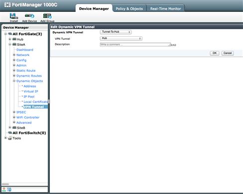
Figure 9.20 Policy Mode IPSec Dynamic Tunnel Binding
Now that we have completed our configuration, we must deploy our configurations to our devices using the Installation Wizard. Once the Policy Packages and Device Settings are pushed to the Hub and remote sites, the network can be tested and used.
Creating and Managing an Interface Mode VPN
Our second example will use Interface Mode IPSec tunnels. While the workflow is similar to building a Policy Mode IPSec VPN, there are some distinct differences. The first is that we will not be utilizing VPN Tunnel Dynamic Objects. As we wish our new tunnels to be treated as interfaces, we will map our new interfaces to Zones. These zones will then be used during policy creation, just as if they were physical interfaces. The second major difference is that we will not use the action “IPSec” when creating our policies. As our policies will reference the zones bound to the IPSec tunnel interface, we will be using policies with the “Accept” action, allowing traffic both to and from our tunnels.
As we are using the same network layout as earlier, we will not walk through creating the Interface Mode IPSec VPN. The same requirements exist: traffic sourced from the internal protected segment (192.168.10.0/24) must reach Sites A and B through the appropriate IPSec tunnels. Sites A and B will again have the same requirements and allow traffic sourced from their protected segments (10.10.25.0/24 and 10.10.50.0/24), to reach the Hub’s internal protected segment via a common policy package.
The steps will be:
• Define Firewall Address Object for the protected subnets.
• Configure our Policy Packages.
• Map Dynamic Address Objects where required.
• Map our Tunnel Interfaces to Zones.
The tunnels will be seen by the devices as interfaces and will be configured as such. To apply policies to devices, the device interfaces must be mapped to Zones. Because we are creating a simple Hub and spoke VPN, we must only create two Zones. One Zone will be used for our tunnel(s) and one will define our internal protected interface (see Figure 9.21).
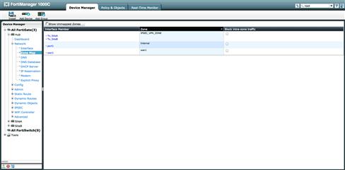
Figure 9.21 Interface Mode IPSec Zone Mappings
We will create two Zones, the first called “Internal” and a second called “IPSEC_VPN_ZONE.” Internal will refer to the protected interface at each device. IPSEC_VPN_ZONE, of course, will refer to our IPSec VPN tunnel. However, not only will it refer to the tunnel at each remote location pointing back to the Hub, but will also refer to any and all tunnels providing secure connections to the remote sites.
In addition to our Zones, we must also create the appropriate Firewall Address objects to define which traffic will be allowed through our tunnel interfaces. We will again keep it simple by creating only two address objects, one defining the protected subnet of the Hub, 192.168.10.0/24, and one summary address that encompasses all remote protected subnets. We have chosen to use a simple byte-boundary bound summary of 10.10.0.0/16.
Depending on how well thought-out your IP scheme is, you can keep the creation of your objects and policies very simple, but understand that if you must create multiple addresses and groups, the management of your Policy Packages is no different than as if you were controlling traffic between any other interface types. Thus, there is no reason to be concerned about needing to readdress your environment. You may just need to have a more robust policy package (see Figure 9.22).
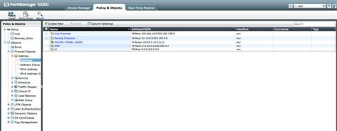
Figure 9.22 Interface Mode IPSec Address Objects
Once the Zone and Address objects are created we may create our Policy Packages. With this method of VPN creation, our Policy Packages can remain fairly basic. Because we are using a Zone to represent the tunnel at our Hub location, we are not required to create an IPSec policy for each individual tunnel as in the previous example. Instead, we will bind each tunnel interface to IPSEC_VPN_ZONE. Another difference is that we will create “Accept” policies for both in and outbound traffic flow, just as we would for any interface pair. This is also the case for the Remote Sites Policy Package, however each remote site will share the same package. For this to be work, we must map each Zone to its respective Tunnels and Interfaces (see Figure 9.23).
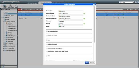
Figure 9.23 Interface Mode IPSec Policy
When we created our Address object for the Remote Site protected segments, we did it using the 10.10.0.0/16 summary. We could choose to use it as is, but we have also chosen to map the Address object at each remote device to a Dynamic Object Address. As described earlier, the Dynamic Address Object allows us to redefine the value of the Address object from the Object Database for a specific device. By defining the object value to that of 10.10.25.0/24 for Site A and 10.10.50.0/24 at Site B, the associated Policy Package, simple as it is, can manage all remote devices and now has very specific device-level meaning, allowing us to granularly control what is and is not allowed for each location. We are not mapping any Dynamic Address Objects at the Hub device, as we will accept the object database values (see Figure 9.24).
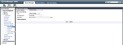
Figure 9.24 Interface Mode IPSec Dynamic Addresss
Like before, the tunnel creation is accomplished by navigating to the IPSec configuration for each device requiring tunnels. At each device, we will apply the appropriate Phase I and Phase II configuration tunnel parameters with the same workflow seen within FortiOS, but for this exercise we are utilizing Interface Mode VPNs and we WILL select “IPSec Interface Mode” during the Phase I creation (see Figure 9.25).
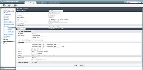
Figure 9.25 Interface Mode IPSec Phase 1 Settings
Now that our interfaces are created, we can map them to the appropriate Zones. We will map each Interface Mode Tunnel at the Hub device to the IPSEC_VPN_Zone and map its protected interface, port1, to the Zone Internal. This will allow our Policy Package to be properly translated to the device and provide the security we desire. Similarly, we will map the Interface Tunnel at each Remote Site to the tunnel built back to the Hub and map the protected interfaces to the Internal Zones, again letting our Policy Package be applied at each device.
The last thing we must do before deploying our configurations is to add the required route. Unlike our Policy Mode configuration, where the default route was sufficient, we will need to have more specific routes defining the path our traffic will take. When a device determines which path specific traffic will take, it consults the routing table. Unlike Policy Mode configuration, where the “External” interface was our egress interface, in Interface Mode the tunnel is our egress interface.
At each remote location, a simple static route pointing toward 192.168.10.0/24 via the tunnel back to the Hub is all that is required. However, at the Hub we will need to be more detailed and ensure we have a route to each remote protected segment that traverses the appropriate tunnel. Our routing will determine which tunnel to send traffic while our policy package will determine if that traffic will be allowed to traverse the tunnel (see Figure 9.26).
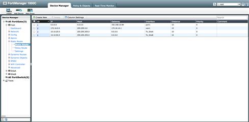
Figure 9.26 Interface Mode IPSec Static Routing Definition
We again find ourselves having completed our configuration can deploy our configurations to our devices using the Installation Wizard described earlier. Once both the Policy Packages and Device Settings are pushed to the Hub and remote sites, you may start testing and using your centrally managed Policy Mode VPN.
Central VPN Console
As you can see, using FortiManager with to maintain a distributed VPN environment has advantages over accessing each device individually. What may also be evident is that, for every device we want to add to the VPN, there are many steps for creating the objects, polices, tunnels, and routing required. The more steps involved with any process, the greater chance for errors to occur causing unwanted results.
To help us reduce the number of steps required to build a VPN network, FortiManager provides a second mode of VPN management. The “Central VPN Console” helps automatically provision IPSec VPN tunnels and routing requirements when creating a large-scale distributed Hub and Spoke or Fully Meshed VPN.
The Central VPN Console is configured on a per ADOM basis, but before an administrator can use this function, they must globally enable the option. To do this, simply navigate to the Admin → Admin Setting section within the System Settings tab, check the option for “Show VPN Console” and select apply. Once this option is selected, the VPN console will show up within those ADOMs where we will change the VPN management mode from “Policy and Device VPNs” to “Central VPN Console” (see Figure 9.27).
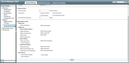
Figure 9.27 Enabling GUI option for VPN Console
If you are not using multiple ADOMs, you will enable the Central VPN Console in the System Information widget of the General → Dashboard within the System Settings tab. If the FortiManager is configured to use multiple ADOMs, enabling the Central VPN Console on a per ADOM basis is accomplished by right clicking and selecting “Edit” for the ADOM to be modified. Once the edit screen for the ADOM appears, change the VPN Management option to “Central VPN Console” and then “OK” (see Figure 9.28).
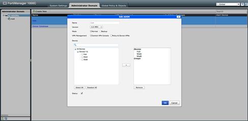
Figure 9.28 ADOM setting for VPN console
Now that we have enabled the Central VPN Console, we may reenter the ADOM and generate our VPN. To punctuate the advantages of using this mode, we reference the same VPN layout as earlier. Assuming your devices are already installed to the FortiManager and your Zones for firewalls are mapped, there are just a few steps to prepare before creating your VPN. There are then a mere handful of actions to define and deploy your VPN.
• Define Firewall Address objects for the protected subnets.
First, we must define a Firewall Address object for each protected subnet. These address objects will be used in our policy creation as before but they will be also used when defining each managed gateway device in our VPN configuration.
Once our address objects are defined, we may construct our VPN. The Central VPN Console is capable of maintaining multiple Star, Mesh, or Dialup VPNs. If we navigate to the Policy & Objects tab, we find the VPN Console nested at the bottom of the left window pane. With our focus on the VPN Console, we select “Create New” and then select a Star configuration for our example. We must then define our Phase I and Phase II configuration. These settings will be used by the VPN Console to create the tunnel configurations on each of the devices which we will add as managed VPN gateways. This allows us to define these settings once for each device in the VPN, eliminating the risk of misconfiguration that occurs when we configure tunnels on a device-by-device basis (see Figure 9.29).
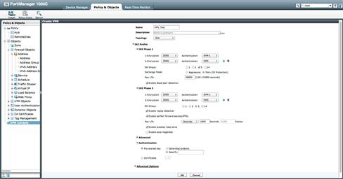
Figure 9.29 VPN Console
After committing our changes by selecting “OK,” our focus will shift to the main screen and require us to select the VPN we just created. To select this, click on the VPN name you wish to manage. Once in the VPN you can select “Create New” to define either a “Managed” or “External” gateway. As each device you create is part of the VPN, and managed by the FortiManager, we will create all of our devices as Managed Gateways.
The first VPN member to be created is the “HUB” in our Hub and Spoke/Star configuration. While there are only a few items to define, there are a few things that will make your first installation go smoothly. Set the “Node Type” to “HUB,” and select the Device named Hub. Then select the Zone name mapped to the outside interface where the IPSec tunnel is created with the value “Default VPN Interface.” At the time of this writing, the name of this value is misleading. The options in the drop down list are Zone names, not physical interfaces. It is likely that this will be renamed in a subsequent software release so it will more appropriately describe the value needing to be selected.
The value “Hub-to-Hub Interface” could also be a Zone name. While supported, in our example we are not creating a dual hub star configuration and will not need to define a Hub-to-Hub connection. If we were to create a dual hub solution, this value would help create an IPSec tunnel between the two hubs for routing of VPN traffic.
Another task we had to perform in the earlier examples was the creation of the appropriate routes to ensure traffic would traverse the correct tunnel when accessing the protected segments. With the VPN console, you can have the FortiManager automatically create the routes. By selecting “Automatic” as the routing value, the FortiManager will take the “Summary Network(s)” and “Protected Subnet” values and propagate them to the remote devices so they can use the tunnels for the correct subnets.
The two values “Summary Network(s)” and “Protected Subnet” are populated with the firewall address objects created earlier. You can use either “Protected Subnet” for individual routes desired to be seen on the remote devices. “Summary Network(s)” can also be used, assuming the summary route is not overly general. This avoids routing confusion at the remote locations (see Figure 9.30).
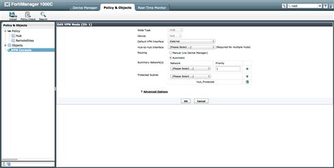
Figure 9.30 VPN Console Hub Setting
Once we commit the configuration for our Hub, we will follow the same process for adding the remote locations as spokes in our VPN. The one difference in the configuration is selecting the “Node Type” as “Spoke.”
Once the VPN is configured, we simply configure our Policy packages to allow the appropriate traffic in and out of the new tunnels. The VPN Console creates the VPN with Interface Mode tunnels, so we will create our policies as “Accept” policies. Another advantage of using the VPN Console is to not have to create Zones and map them to the interfaces at each individual device.
When using the VPN Console, FortiManager automatically creates three different Zones to be automatically mapped to the appropriate interface based on our configurations when adding devices into the VPN Console. These special Zones appear as options for the source and destination Zones when creating policies in our policy packages. Each Zone name will be created with three values separated by the “_” character. The first value is “vpnmgr” to identify that the Zone was created by the VPN Console. The second value will be the VPN name used when the VPN was created, allowing you to select to correct Zone when multiple VPNs are defined.
The third is one of the three values. The first of these, “hub2spoke,” is used to identify the source and/or destination Zone when defining the policy for the Hub. The second of these values, “spoke2hub,” is used to identify the source and/or destination Zone when defining policy for the spokes. The last of these values, “mesh,” is used to identify the source and/or destination Zone by all locations in a full mesh VPN.
In our example we find the Zones vpnmgr_VPN_Test_hub2spoke, vpnmgr_VPN_Test_spoke2hub, and vpnmgr_VPN_Test_mesh. For those paying attention, you may have noticed a third “_” between the words “VPN” and “Test.” This underscore is actually part of the name “VPN_Test” used when we initially created our VPN. All spaces in VPN names will be converted to underscores when accessed in this manner (see Figure 9.31).
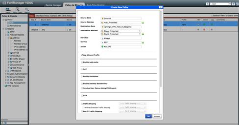
Figure 9.31 VPN Console Hub Policy
We once again find ourselves having completed our configuration and may deploy our device and policy package configurations. Like before, once both the Policy Packages and Device Settings are pushed to the Hub and remote sites, you may begin testing and using your centrally managed Policy Mode VPN.
Conclusion
While we have just scratched the surface on FortiManager, we hope this overview gives you a good understanding of its capabilities and a head start for deploying FortiManager into your environment.
In the absence of a FortiManager-specific publication, please refer to the following link for the FortiManager public documentation. Fortinet continues to deploy new features, so please keep current on both the documentation and your licenses, so your device continues to meet your needs.