
Chapter 4
Connectivity and Networking Technologies
Information in this chapter:
• Dynamically Addressed Interfaces
- RIP (Routing Information Protocol)
- OSPF (Open Shortest Path First)
- BGP (Border Gateway Protocol)
- IS-IS (Intermediate System to Intermediate System)
- BFD (Bidirectional Forwarding Detection)
Operating Modes
As noted previously, a FortiGate can be configured to operate either in Transparent mode, like a switch (L2 based forwarding) or in NAT/Route mode, like a router (L3 based forwarding). Thus, the way in which packets are treated will depend on which of these two modes the device is in.
Layer 2 (Transparent)
This mode of operation is also commonly referred to as bridged mode, as the operation is very similar to that of a Layer 2 bridge or switch. The default operating mode for a FortiGate or a newly defined VDOM is always L3 mode. Changing the mode is as simple as using the link in the System Information widget on the main status page. Once selected, you will be prompted to specify the IP address and default gateway information for the device to use after the mode has been changed. This IP address will be used for accessing the FortiGate administrative interfaces. As noted in previous chapters, changes like this take place immediately, so it is important to use an address that will remain reachable. It would also be a good idea to verify that the planned network interfaces over which the WebUI will be accessed have sufficient administrative protocols configured at System → Network → Interfaces. If you are using the CLI, you will also need to configure the IP address and the default gateway.
FGT (settings) # set opmode transparent
FGT (settings) # set manageip <ip: x.x.x.x> <subnet: x.x.x.x>
When operating in Transparent Mode it is critical that you install and configure the FortiGate in configuration that avoids creating network loops. Much as L2 switches do, a FortiGate tracks all ARP request/reply transactions and builds a table of IP/MAC/interface values. This table is consulted for each new packet received so the correct egress interface can be determined and, therefore, linked to correct firewall policies. When the FortiGate receives a packet with a destination IP and/or MAC that is not in the current table, the FortiGate will flood the packet out to all allowed interfaces.
In some networks the Spanning Tree Protocol (STP) may be used to avoid creation of network loops, the FortiGate device itself does not participate in STP, it can however forward STP packets, this is enabled from the CLI by setting the option stpforward to enable for the appropriate interfaces.
Layer 3 (NAT/Route)
Layer 3 is the traditional operating mode for most firewalls. In this mode, the interface from which a packet is forwarded is based on the routing table.
Connectivity
The FortiGate product family supports a number of different types of network interfaces. While these are primarily 802.3 Ethernet interfaces, 802.11 Wireless, ADSL2/2+ modems, Analog Modem, RS232 and USB connected modems are also supported. At this time, there is currently no support for any of the traditional wide area connection technologies such as ATM, T1/T3, etc.
Some models support modularity, allowing for different types of physical interface to be combined. These include RJ45, Short-Haul multimode fiber, Long-Haul multimode, and/or singlemode fiber. Some of the more recent models also support SFP (1 Gbps) interfaces. The top end of the product line also supports SFP+ (10 Gbps) interfaces. The SFP+ interface is physically plug-compatible with its predecessor, the SFP. These are often incorrectly referred to as GBIC’s, but are not the same as Cisco’s older socket technology.
Dynamically Addressed Interfaces
Any Ethernet interface on the FortiGate can be configured to support dynamic IPV4 addressing via DHCP or PPPoE. Both of these protocols normally provide next-hop gateway information which the FortiGate can either accept or ignore depending on the setting of the “Retrieve default gateway from server” option. When enabled, the default route provided is installed into the local routing table. If the option is disabled, the provided route will not be installed. In the CLI, this setting is defined as “set defaultgw enable” under the interface parameters.
When using dynamically addressed interfaces, it won’t be possible to configure your DNS to allow access to the device by name, as the addresses will periodically change. A simple solution to this is to enable the FortiGate’s integrated support for Dynamic DNS. When this is enabled, the FortiGate will update a Dynamic DNS system on every address change. Support includes a number of commercial providers and one generic service. The Dynamic DNS configuration can be edited from both the WebUI and the CLI.
VLAN Interfaces
All of the FortiGate units with the exception of the smallest of the entry-level models support the use of VLANs (virtual LANs) as defined by the IEEE 802.1q specification.
A VLAN is a method of allowing multiple distinct networks to operate over the same physical infrastructure, the packets associated with each of these distinct networks are identified by the use of additional data in the packet, commonly referred to as a VLAN tag, these tags are used by the physical network components to isolate the packets for each distinct (or virtual) network, this includes the FortiGate.
A virtual VLAN interface is needed for each VLAN that needs to have security enforcement performed, these can be created from the WebUI by navigating to System → Network and clicking on the Create New button, in the edit page change the interface type option to VLAN interface and specify the physical interface this VLAN is to be associated with and then specify the VLAN tag that identifies the traffic. From the CLI, you will need to set the interface type to VLAN in order for the remaining required configuration options to become available, you will also need to assign the new interface to a VDOM, if you do not have VDOMs enabled then you will still need to assign the interface to the root VDOM.
FGT (interface) # edit port1.10
FGT (port1.10) # set type vlan
FGT (port1.10) # set vlanid 10
FGT (port1.10) # set vdom root
You can use the same VLAN number only once per physical interface, however you can use the same VLAN number on different physical interfaces.
If you are configuring your FortiGate to operate in Transparent mode there is a potential challenge with VLANs. A packet received on one VLAN could potentially be flooded out to all the other VLANs interfaces, resulting in looping. ARP requests, in particular, are a common cause of this type of loop since they are L2 broadcast packets that need to be forwarded. To prevent this type of loop, it is critical that you ensure those packets are contained to their correct broadcast domain. This isolation is ensured with the “forward-domains” FortiOS feature, defining groups of interfaces that belong to the same L2 broadcast domain. This option is currently only available from the CLI. Normally, to configure this feature, you would have the VLAN pairs on the corresponding 802.1q trunks configured into unique forward-domains.
FGT (interface) # edit “port1.10”
FGT (port1.10) # set vdom “root”
FGT (port1.10) # set forward-domain 10
FGT (port1.10) # set interface “port1”
FGT (port1.10) # set vlanid 10
FGT (interface) # edit “port2.10”
FGT (port2.10) # set vdom “root”
FGT (port2.10) # set forward-domain 10
FGT (port2.10) # set interface “port2”
When creating a firewall policy that references an interface in a forward-domain, the only other valid interfaces are those in the same forward-domain. An attempt to use a combination of interfaces that aren’t in the same forward-domain will result in an error.
Beginning with FortiOS 4.3, there is a simplified version of the forward-domain configuration, referred to as a “port-pair.” Only two interfaces can be configured into a port-pair and all lookup functions are disabled. Thus, it is assumed that a packet received on one port-pair interface has only one egress option: the other interface in the pair. Therefore, there is no need to perform any IP/MAC table lookups. This feature can be created from the WebUI by navigating to System → Network → Interface→, there is a small arrow on the right of “Create New,” click on it and select port-pair, select the two interfaces to use in the newly defined port-pair. When creating a firewall policy for traffic transiting the port-pair interfaces, the correct alternate interface is automatically filled in when either interface is selected.
There may also be situations where you are only interested in providing security controls on some VLANs within an 802.1q trunk. By default, when a packet is tagged for a VLAN that is not configured for a specific interface, it is dropped. However, you can configure the FortiGate to simply forward the non-matching packets out the corresponding interface without being processed by the FortiGate. This is accomplished using the “vlanforward” option on both interfaces.
802.3AD
Commonly referred to as Link Aggregation, this widely implemented industry standard allows the network architect to design an infrastructure that increases potential throughput and resiliency without the additional complication of the Spanning Tree protocol.
To avoid communication mismatches, a Link Aggregation interface must be created using identical physical interfaces. Once a physical interface is added to an aggregate interface, it is no longer available for any other configuration.
Aggregate interfaces can be created from either the WebUI or the CLI. From the WebUI:
1. Navigate to System → Network → Interfaces → small arrow on the Create New button.
2. Select the interface option from the pull-down list.
3. Use the displayed dialog to
c. Set the type to “802.3ad link aggregation.”
d. Select the physical interfaces that you wish to use in the bundle.
From the CLI, the configuration steps would be similar to the following:
When an aggregate interface is created, there are a few additional configuration options available that provide for control over the behavior. These will be explained later in this chapter.
Once created, the Aggregate Interface can be used just like a physical interface, including adding VLANs, defining policies, etc.
A Link Aggregation interface can be optionally configured to support the LACP protocol, as defined by the IEEE. By default, when a new Link Aggregation interface is created, LACP is disabled. Enabling LACP is only possible from the CLI. This is where you define support for both Active and Passive modes as well as slow and fast LACP PDU intervals. You can also choose the algorithm used for distributing packets across the member interfaces, based on the L2, L3, or L4 information.
When using Link Aggregation in conjunction with an HA cluster configuration, there are few additional factors to keep in mind. If both units in an Active-Active cluster are connected to the same external Link Aggregation, then it is important that both units send/receive LACP packets so that all the interfaces are operational. The default behavior is for the slave unit to not send LACP PDUs. If the cluster is configured as an Active-Passive cluster then it is important to ensure that the slave unit does not send LACP PDUs to the external systems, as that would indicate to it that the path is valid. This would result in packets being sent to the Passive unit as well as the Active and since the Passive unit would not be passing traffic, the connection could experience high latency or outright disruption.
Redundant Interfaces
This configuration option provides some of the benefits of 802.3ad Link Aggregation without the complexity and potential interoperability challenges. It addresses the common requirement to deploy security products with as much resiliency as possible, providing physical link resiliency.
Much like an aggregate interface, a redundant interface is a virtual interface that is composed of a set of physical interfaces. Once a physical interface is assigned to a redundant interface, it is no longer available for use anywhere else in the configuration such as routing or firewall policies.
Creating a Redundant Interface is similar to creating a Link Aggregation interface. If using the WebUI:
1. Navigate to System → Network → Interfaces → small arrow on the Create New button.
2. Select the Redundant Interface option from the pull-down list.
3. Use the displayed dialog to
a. Select the interfaces you wish to add to the Redundant Interface definition.
If using the CLI, you can issue the following commands:
FGT (interface) # edit <new interface name>
FGT (port1) # set vdom <vdom name>
FGT (port1) # set type redundant
FGT (port1) # set member <intf name> [ <intf name> .......] <other interface parameters as required>
Once created, the Redundant Interface can be used just like a physical interface.
FortiOS performs dependency checking to ensure that an object can be safely added/deleted/modified. If you do not see the physical interfaces that you wish to use, it means that it must be in use in the configuration of another object such as DHCP server, firewall policy, or even address objects. If you are unable to locate a dependency for an interface, you can use the following command to locate all the references: diagnose sys checkused system.interface.name <intf name>
Wireless
The most straightforward way of implementing a secure wireless solution for a small physical location is to deploy a single FortiWifi appliance rather than a FortiGate appliance. These devices are essentially regular FortiGates with the addition of an integrated 802.11 wireless radio. By default, the wireless radio appears as a unique physical interface. Firewall policies control the traffic that is allowed to and from this interface. It is sometimes desired to have the wireless and wired networks bridged together to create a single Layer 3 network that spans both physical media. Because this is a rare use case and, in some cases, is considered dangerous, it cannot be configured through the WebUI. However, it is possible to do via the CLI.
FGT# config system switch-interface
FGT (switch-interface) # edit <new interface name>
For a larger implementations, where the physical area needing to be covered is greater than the range of a single FortiWIFI, there Fortinet lightweight access points (LWAPs) should be considered. These lightweight access points are connected to a FortiGate (or FortiWifi) via an ethernet connection and accept their configuration from the FortiGate/FortiWifi. Traffic is received on these LWAPs and sent back across the wired connection via an encapsulating protocol based on CAPWAP. CAPWAP is an open standard.
Regardless of the deployment method used (standalone or LWAPs), the configuration process is pretty much the same. There is support for multiple SSIDs, each SSID appearing as a separate interface, allowing the administrator to configure unique security policies per SSID. Each SSID can also have unique configuration for various wireless parameters, such as encryption type, whether a portal is in use, etc.
To create a new SSID and its accompanying virtual interface, navigate to the Wireless Controller section of the WebUI, then to Wifi Network → SSID → Create New. At this point, you will be presented a page that looks very similar to the regular interface page, but also includes the configuration of the wireless parameters such as SSID, security mode, authentication requirements, and even the possibility of a custom authentication portal.
If you are deploying a LWAP configuration you will have to assign the LWAPs to the SSIDs before they are able to provide service.
Modems
Some of the FortiGate models such as the 60CM and 80CM are available with integrated wireline modems, other FortiGate models also support a variety of 3G/4G cellular data modems connected to their USB interfaces.
Both types of modems have nearly identical methods for configuration and use. The modem can be used as a standalone interface for locations where there may not be any traditional broadband connectivity available. They can also be configured as a backup interface for a regular physical interface.
IPv6 Interfaces
All of the above interface types, as well as the physical interface, can be configured with an IPv6 address. If both are configured, the interface is essentially in dual stack mode. If you only want an IPv6 address on an interface, simply set the IPv4 address to 0.0.0.0 or use the unset ip configuration option. The IPv6 configuration for an interface is implemented as a sub-table within the existing interface configuration, all IPv6-related parameters are configured here, including administrative access to the FortiGate via IPv6. You can also configure the IPv6 information from the WebUI, however you will first have to enable the display of this in the WebUI, by default the IPv6 configuration options are disabled to keep the WebUI simple. To enable the display of IPv6 in the WebUI, navigate to System → Admin → Settings, under the Display Options in GUI section there is a checkbox for IPv6, selecting this and clicking on apply will result in the IPv6 configuration options being displayed where appropriate in the WebUI.
FGT (ipv6) # set ip6-address <IPv6 address and prefix>
FGT (ipv6) # set ip6-allowaccess [http|https|snmp|ping|telnet|ssh|fgfm]
If you want the FortiGate to send IPv6 router advertisements, you cannot use the interface as a SLAAC (StateLess Address Auto Configuration) client interface.
You can configure IPv6 addresses for the interface much like IPv4:
FGT (ipv6) # config ip6-extra-address
FGT (ip6-extra-address) # edit <additional IPv6 address and prefix>
IPv6 StateLess Address Auto Configuration of the interfaces is not enabled by default, but is supported on any interface once the autoconf parameter is used to enable IPv6 on the interface. This method is normally only used on client devices, not multi-homed devices such as the FortiGate.
The normal configuration has the FortiGate providing auto configuration information in response to a SLAAC request from other devices. To enable this, you will need to add the prefix and set the autonomous flag on that interface. Obviously, this prefix should include the address assigned to the FortiGate interface.
FGT (ipv6) # config ip6-prefix-list
FGT (ip6-prefix-list) # edit <IPv6 Prefix>
The onlink-flag parameter above indicates that the prefix applies to the physically connected network, as opposed to prefixes that are indirectly connected.
Routing
This section is not intended to provide a detailed explanation routing protocols. That is far beyond the scope of this book, and there are many very good books available that deal solely with these routing protocols. The focus is to help the administrator get started with routing, and cover issues that are more specific to FortiOS.
It is important to understand how FortiOS internally handles routing updates, particularly when it comes to planning a HA configuration. The software that implements routing runs in what is commonly referred to as “user space.” This prevents faults or attacks on this component from impacting the kernel. In such instances, the user space applications will crash and be automatically restarted. Since the firewall engine runs inside the kernel, it is necessary to import the route information from the various routing protocols into the kernel’s Forwarding Information Base or FIB. The FIB is the kernel structure that is used to determine the correct egress interface and next-hop gateway for every packet flow. This implementation also allows the kernel to learn the best route for a destination regardless of the routing protocol from which the information is obtained. To view the kernel routing table you use the CLI command “diagnose ip route list.”
With the exception of Static Routes, which apply regardless of layer mode, this section only applies to FortiGates running in L3 NAT/Route mode.
Static Routing
When the FortiGate is deployed as a perimeter device, static routing is the most common routing implementation. This is particularly true when there is limited internal L3 network segmentation. Typically, one default route points toward the Internet and any other routes exist to route internal traffic toward the internal routers.
When running in Transparent mode, this is the only method of routing supported. In some situations, particularly when there are internal routers, you will need to be careful about how you define the static routes. If you use a single default route pointing toward an Internet router, it may become possible for the FortiGate’s firewall engine to view the data path as asymmetric. This will result in dropped packets. To avoid this, it is wise to always configure an internal static route that uses the correct internal interface of the FortiGate and a default route that directs Internet traffic to the external interface. The default route toward the Internet is also required for the FortiGate to be able to retrieve service updates from the FortiGuard network (see Figures 4.1 and 4.2).
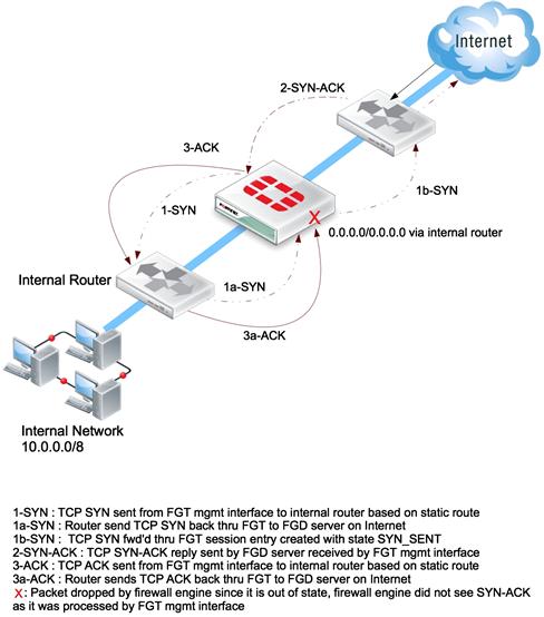
Figure 4.1 Two Different TP Mode Scenarios where a Single Default Route will Result in Traffic Problems
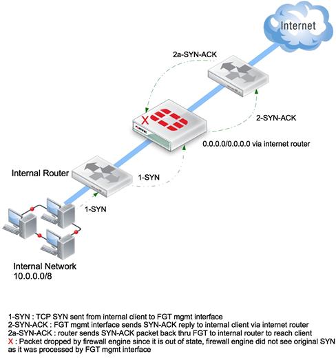
Fgure 4.2 Two Different TP Mode Scenarios where a Single Default Route will Result in Traffic Problems
When you initially change a FortiGate to operate in TP mode, you will be prompted to enter a default gateway. When using the CLI, adding additional static routes as required is no different than when routing in NAT/Route mode. However when running in TP mode, you must add the required static routes under System → Network → Routing Table (see Figure 4.3).
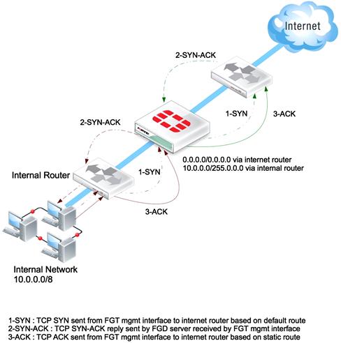
Fgure 4.3 Both Solutions can be Solved by Specifying both a Default Route to the Internet and Specific Routes for the Internal Networks that are behind the Internal Router
Policy-Based Routing
Most commonly used in a perimeter deployment when there are multiple connections to the Internet. Policy-Based Routing (PBR) allows the network architect to alter the normal routing behavior for traffic flows in ways that are not limited only to the destination IP address. This routing can include the destination port, the source address (or range/subnet), the IP protocol number, or even the incoming interface.
For example, you may prefer all Web Browsing and similar (perhaps user interactive) traffic to access the Internet via one Internet provider while all other traffic is sent via an alternate provider. This can be useful when one provider charges a premium for a very low-latency service, which you would use for traffic that requires this low latency, such as VOIP.
When you are creating a Policy Route for a specific protocol, such as SMTP, it is important to specify both the protocol (6 for TCP) and the port (25 for SMTP). If the route only involves a single port, both the start and end port will be the same. If you attempt to create a Policy Route for a specific port and you neglect to specify a specific protocol, the system will not understand your meaning. As a result, your changes will not be accepted and will be lost.
Polity route statements are processed in a similar manner as firewall policies—top-down, with the first match winning. New policy routes are always added to the bottom of the list. If you need to change the position of a statement, you will need to select the new policy route using the checkbox and then use the “Move To” option from the menu bar to change its position. From the CLI, you use the “move” command followed by the “before” or “after” keyword and then the ID number of the policy to which you wish to move the policy route.
In this example, we assume that there is an existing policy route configuration that forces all HTTP traffic out the WAN2 interface. However, we need to change the system such that traffic from a specific source exits WAN1. However, when we create this rule, the traffic continues to follow the original path, due to the top-down processing.
To resolve this, we need to use the “move” command to change the ordering of the policy routes.
Now the policy routes are in the desired order and traffic will be forwarded as expected.
Dynamic Routing
FortiOS, when configured in L3 (NAT/Route) mode, has supported the most common open routing protocols since version 3.0. The support for these routing protocols has been enhanced over time, and newer protocols have been added. Another significant area of improvement has been the addition of support for IPv6 information.
These dynamic routing protocols are commonly broken into two major categories: Interior routing protocols or IGP (Interior Gateway Protocols) and Exterior routing protocols or EGP (Exterior Gateway Protocols). An IGP is typically used within a single organization, while an EGP is typically used to connect disparate organizations or large Enterprises to the Internet. RIP and OSPF are examples of IGP, while BGP and IS-IS can be used as either an IGP or EGP.
When VDOMs are implemented on a FortiGate, the routing information is isolated per VDOM. This allows for complete independent configuration and for overlapping or duplicated IP address space to be used by various VDOMs.
If your configuration consists of multiple L3 VDOMs and you want to exchange routes, you’ll need to set up peering across inter-VDOM links connecting the VDOMs. For example, a service provider might have a routing VDOM that connects to a number of customer VDOMs.
RIP (Routing Information Protocol)
Unlike the other routing protocols, there are actually two different versions of RIP. The original RIP v1/2 protocol handles IPv4 routing. RIPng as the next generation, however, supports IPv6. Each is configured independently.
It is commonly assumed that RIP is no longer appropriate as a routing protocol, primarily due to its behavior of frequently sending the entire local forward database to all peers. However, there are still architectures where it is appropriate. It is particularly appropriate in architectures that require dynamic routing support but also a very fast convergence time. For example, consider a distributed IPSec hub-and-spoke topology that leverages dialup as well as redundant tunnel configurations.
OSPF (Open Shortest Path First)
The most common use of this routing protocol is to facilitate route updates within a single organization, often to support an IPsec-based distributed network. It is designed to support large distributed networks via “areas”. These areas are numbered with a dotted quad notation, much like IPv4 addresses. These areas are always connected to 0.0.0.0, which is commonly referred to as the backbone area.
BGP (Border Gateway Protocol)
As the de facto routing protocol of the Internet, BGP has two common deployment models. When used for internal routing within a single administrative domain, BGP is also referred to as iBGP. When used to send routes outside of this domain it is commonly referred to as external BGP.
BGP provides extensive control over the propagation of network topology information… so much so that it is often viewed as overly complicated.
The BGP routing protocol uses a TCP connection to each peer to both transmit routing information and ensure the viability of the peer. This also means that there is a requirement for the administrators of each end of the connection to cooperate. It is not normally possible to establish a BGP peer by configuring the IP address of the peer on only one side of the connection.
While there is support for configuring BGP in the WebUI, this is really only sufficient to get the most basic BGP configuration up and running. You can define your local Autonomous System (AS), router ID, interfaces and networks to be propagated. More advanced configuration will require the CLI.
One of the original design requirements was that BGP be extensible. This is implemented via “capabilities”. There are a number of capabilities defined by various RFCs. The most commonly used are the “route-refresh” and “graceful-restart” capabilities. Capabilities are negotiated between the peers during the initial establishment of a BGP session and can be disabled or enabled on a per-neighbor basis. The graceful-restart capability can also be enabled/disabled globally.
One useful configuration parameter that is disabled by default is the ability to generate log messages whenever there is a neighbor change. If you are using BGP, you should seriously consider enabling this. Otherwise, a routing change could occur invisibly and be extremely difficult to troubleshoot.
Native IPv6 peering is supported in BGP. To configure an IPv6 peer, you enter an IPv6 address when configuring the neighbor and specify the networks using the “config network6 option” instead of the IPv4-based “config network”. Similarly, there are separate IPv6 versions of commands that must be used to define things like aggregation and redistribution.
When deploying a FortiGate solution in a HA configuration, the graceful-restart capability should be enabled on both the FortiGate and the appropriate peers. This capability allows for one peer to notify another when there will be a temporary failure. The result is that, for a period of time, the peer should not drop any routes learned from the failing router. This allows traffic to continue to be forwarded by the routers (using the old routing information) until the TCP peer connection can be rebuilt. When the FortiGate cluster is undergoing a role change, such as during a firmware upgrade, before failing over, the FortiGate sends a graceful-restart message to the configured peers. This way, they will continue to use their old routing information until the peer can be re-established.
IS-IS (Intermediate System to Intermediate System)
Primarily seen in carrier networks and large enterprise private WAN implementations, IS-IS is considered a possible successor to BGP.
At this time, there is no WebUI support for configuring IS-IS. It is CLI only. However, routes learned via IS-IS are displayed in the WebUI Route Monitor.
Route Redistribution
It is fairly common to have multiple routing protocols running on the same router, since the routing protocols are independent; the routes learned are also independent. Route Redistribution allows routes learned via one routing protocol to be propagated by a different protocol.
One of the more common uses of redistribution is for resilient VPN configuration when using a dial-up or dynamic VPN gateway. When an IPsec Phase2 Security Association is negotiated, and you have enabled redistribution of connected routes, it will be redistributed into your internal routing protocol.
You can configure a route-map to control what routes are redistributed into the target routing protocol. For example, if you are learning both RFC-1918 addresses and public Internet address information for internal networks, you won’t want to publish the RFC-1918 addresses into your Internet BGP peering connection.
Route redistribution is enabled on a per-protocol basis.
Multicast
Multicast is usually only required when the FortiGate is being deployed at perimeters for internal security zones and not at the Internet perimeter. PIM Sparse and Dense modes are both supported when the unit is operating in NAT/Route mode. When running in Transparent mode, there are two deployment options. One is to have the FortiGate forward any multicast packets without evaluating them against the security policies. The other option is to explicitly configure multicast firewall policies to allow only those desired. The first option is enabled from the CLI using the following command:
Currently, the only way to create multicast firewall policies is via the CLI. They are separate from the regular firewall policies.
FGT # config firewall multicast-policy
FGT (multicast-policy) # edit 1
FGT (1) # set srcaddr 192.168.0.1 255.255.255.255
FGT (1) # set dstaddr 224.0.0.5 255.255.255.255
FGT (multicast-policy) # edit 2
FGT (2) # set srcaddr 0.0.0.0 0.0.0.0
This would only allow the OSPF router with the interface address of 192.168.0.1 to forward multicast packets through the FortiGate.
If you are using multicast security policies in Transparent mode, you may run into an issue with the Multicast TTL value. Some multicast protocols require the TTL value to be a known value. By default, when a packet is processed by the security policy, the TTL value in the packets gets decremented. This will break the protocol. To avoid this situation, you can use the “set multicast-no-ttlchange” option from the CLI.
ECMP (Equal Cost MultiPath)
ECMP is less a protocol than a method for improving utilization of multiple paths to the same destination network. As the intent is to ensure that the same session or flow always uses the same egress interface, ECMP examines more than just the destination address when making a forwarding decision. The default method for making this decision is to track the source IP address and alternate through the list of eligible egress paths for each unique source/destination IP address pair. There are two other methods available as well. The first method (Weighted Load Balance) allows you to configure a weight for each interface. This determines the ratio used to split the flows across the interfaces. For example, if you set the weight on one interface to 100 and the weight on another to 50, this will result in twice as many flows being handled by one interface. The second method is referred to as “spillover”. This method ignores the less-preferred interfaces until the preferred interface hits a specific bandwidth utilization level. This is most appropriate when the egress interfaces have dramatically different performance characteristics, such as a 10 Mbps Metropolitan LAN type connection with an ADSL2 alternate connection.
You can choose the ECMP method via the WebUI by navigating to Router → Settings and selecting the desired configuration from the set of radio button options. If you are using either the weighted or spillover options for ECMP, you will need to configure the weight or spillover amount for each interface in the same location as the other interface specific configuration options: System → Interface → interface_name (see Figure 4.4).
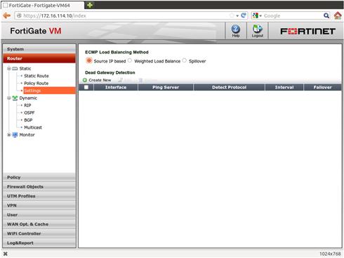
Fgure 4.4 ECMP (Equal Cost Multiple Path)
Similarly, the configuration from the CLI is performed in two separate locations. The ECMP mode is configured under system settings, and the weight or spillover values are configured within the interface parameters.
To enable Weighted Load Balance ECMP
FGT (settings) # set v4-ecmp-mode weight-based
FGT (settings) # set v4-ecmp-mode usage-based
To reset to the default of source-IP based ECMP
FGT (settings) # set v4-ecmp-mode source-ip-based
Per interface configuration when using Weighted Load Balance ECMP
FGT (interface) # edit <interface name>
FGT (port1) # set weight <integer for ratio, 0-255>
Per interface configuration when using Spillover ECMP
FGT (interface) # edit <interface name>
FGT (port1) # set spillover-threshold <integer for rate in Kbits/second>
You can have both weight and spillover options configured for an interface. The one that will actually be applied depends on the current setting of the “v4-ecmp-mode” variable in systems settings.
[VDOM Note] When a FortiGate is operating with multiple NAT mode VDOMs, the ECMP method can be specified per VDOM
[IPv6 Note] The ECMP configuration is the same for both IPv4 and IPv6
You will still need to correctly configure your firewall policies for all interfaces being used. If you are using two interfaces, you will need to configure the policies twice, once for each interface. You can optionally configure the interfaces into a Security Zone to simplify this. This would require the administrator to only configure a single set of egress policies. However, when interfaces are configured into a Security Zone, you lose the ability to use the interfaces independently within a firewall policy. You must choose one way or the other. The primary reason for wanting separate firewall policies would be that you don’t want all traffic to pass over all interfaces. For example, if you have configured a modem as a backup interface to a low-latency and high-bandwidth Internet connection, when failure occurs, the routing decisions must differ. Since VOIP is unlikely to work across a high-latency modem and general web browsing will quickly consume the limited bandwidth, these protocols could be blocked from that route. This would leave capacity free for critical credit card and inventory search transaction.
BFD (Bidirectional Forwarding Detection)
This protocol is defined by two IETF drafts, the purpose of which is to allow a given device the ability to detect whether the path to the next router is valid in both directions. This protocol needs to be implemented on both ends of a physical link and is specific to that link only. In other words, it validates the reachability of the router and its ability return traffic, thereby verifying the underlying L2 connectivity.
Information and Troubleshooting
To retrieve the current operating status for routing protocols, you will use the “get router info” or “get router info6” commands. There are a large number of sub-options available to show you the status and information appropriate to each routing protocol. For example, “get router info bgp summary”, or “get router info ospf status”. The sub-options vary by routing protocol.
You can obtain run-time information for the various routing protocols from the CLI via the “get router info <protocol> <options>” command. If you are concerned about IPv6, the command differs by only one character: “get router info6 <protocol> <options>”. The type of information available depends on the routing protocol. For example, with OSPF, you can obtain information on the adjacencies, the interfaces running OSPF, the database, etc. In contrast, for BGP, you can get information based on Autonomous System info, community information, neighbor information, the application of route-maps, and prefix-lists, etc.
database show ospf database information
interface show ospf interfaces
border-routers show ospf border routers
virtual-links show ospf virtual links
cidr-only display routes with non-natural netmasks
community display routes matching the communities
community-info list all bgp community information
community-list display routes matching the community-list
dampening display router dampening infomation
filter-list display routes conforming to the filter-list
inconsistent-as display routes with inconsistent AS Paths
network show BGP info for network
network-longer-prefixes show BGP info for route and more specific routes
prefix-list display routes conforming to the prefix-list
regexp display routes matching the AS path regular expression
quote-regexp display routes matching the AS path “regular expression”
route-map display routes conforming to the route-map
There are also debug options available under “diagnose ip router <protocol>”. Generally speaking, you enable debugging for the type of information that interests you and then you define the level of detail that you want.
FGT # diagnose ip router bgp level info
FGT # diagnose ip router bgp events enable
To see what level and type of debug messages are being generated:
To disable all currently enabled debug information
Servicing users
There are many technologies today that are intended to simplify the lives of network administrators. Of course, even with these technologies, managing, and administering a widely distributed IP-based network becomes even more complicated. The two most important services are DHCP and DNS. The former allows a device to automatically configure its network parameters while the latter allows a system to be able to connect to another system without having to remember numerical IP addresses. DNS also allows the services to move around fairly transparently, as DNS changes can be made within the DNS list and not on each individual client. A stable and reliable DNS deployment becomes even more important as people migrate to IPv6. This is not simply because IPv6 addresses, being up to four times longer than IPv6, are hard to remember, but also to facilitate the transition from IPv4 to IPV6 for both clients and servers.
DHCP
A FortiGate unit can make use of DHCP services in a one of two methods, as DHCP Client and as a DHCP server. Any interface can be configured to obtain its address via DHCP. This is mostly used on the entry-level products, so they can be connected to a broadband Internet provider. Configuring this is as simple as selecting the option in the WebUI. If needed, there are a few of additional options. “Override internal DNS” will replace the statically configured DNS details with the DNS servers provided in the DHCP process. The “Retrieve default gateway from server” controls whether or not the default gateway obtained via the DHCP process is installed in the routing table. You may not want to enable this option if you are using DHCP to assign an address to an internal interface.
When running as a DHCP Server, the FortiGate can provide DHCP services for multiple interfaces simultaneously. When operating as a DHCP Server and configured in an HA cluster, the lease information is synchronized between cluster members so that a failover between cluster members will not result in duplicate leases being handed out.
The DHCP server supports configuration options that should be sufficient for nearly any environment. This includes the ability to assign all the expected values to a client: IP Address, domain name, default gateway, subnet mask, up to two WINS servers, up to three DNS servers. The DNS servers can either be manually configured addresses or the addresses currently in use by FortiOS. It also supports address reservations and exclusions, as well as custom option fields. These custom fields are most commonly used for devices like VoIP phones, to provide information for the device to load its firmware and configuration.
The FortiGate can provide DHCP services to not just locally connected devices but also to remote client systems connecting to the FortiGate system via IPSec tunnels. Leveraging this capability allows internal systems or firewalls to treat traffic that originates from the IPSec gateway differently from other traffic. It also allows all the remote users to be sourced from a specific range of IP addresses.
In larger customer environments, an IPAM (IP Address Management) appliance or application is often deployed to allow for simpler management of DHCP configuration. To take advantage of this, the FortiGate must be configured to forward locally occurring DHCP requests to this centralized service. This is done by configuring the FortiGate interface as a DHCP relay and specifying the IP address of the IPAM system.
DNS Server
DNS (Domain Name Services) is one of the most important services for users on a network. Most users remember services by name, not number. Also, the use of names makes the physical location of a service portable. As the deployment of IPv6 becomes more prevalent, the use of DNS will pretty much become a requirement as the length of the new addresses makes them very difficult to remember.
There are a number of different ways that DNS can be configured on a FortiGate. The simplest is to have the FortiGate transparently forward DNS requests received to the DNS servers configured on the FortiGate. This process is referred to as DNS-forwarding. If the FortiGate is connected to the Internet via a service that uses dynamically assigned addresses, then it is important to configure the FortiGate to accept and use the DNS servers advertised by the provider rather than the default DNS servers. This happens by default when the interface is configured via the WebUI. If, however, you are configuring the interface from the CLI, then you should include the CLI command “set dns-server-override enable” in the interface parameters. This option will appear in the WebUI as “Override internal DNS” when the interface is configured to use either DHCP or PPPoE.
Efficient DNS are important not only for accessing Internet sites, but as the corporate infrastructure grows; the DNS environment becomes more critical. This growth often involves the deployment of DNS Servers in remote locations. In a server-centric environment, this typically results in an increased burden on operations and maintenance. As of FortiOS 4.3, however, this functionality can now be off-loaded to the FortiGate appliance.
Virtual Domains (VDOM)
The separation of VDOMs is so complete that you can have both Transparent and NAT/Route mode VDOMs on the same physical device. This leads to some interesting possibilities, such as using some of the FortiGate to provide NAT/Route perimeter firewall functions while using a different set of interfaces to provide a focused in-line IPS/Application Control solution for an internal segment.
High Availability
There are a wide variety of options when deploying or designing a Highly Available FortiGate solution. The most common of these being the Fortinet-specific HA feature. The FGCP (FortiGate Gateway Clustering Protocol) consists of two or more identical FortiGate units. In addition to the more traditional Active-Passive configuration, the cluster can be deployed in an Active-Active mode, where all the cluster units are used to perform content layer inspection on the traffic. Regardless of the mode, the configuration consists of a number of components including: configuration synchronization, session synchronization, and cluster membership monitoring.
One current limitation that may prevent the use of FGCP HA is that currently FortiOS cannot operate in either a Active-Active or Active-Passive HA cluster if any of the interfaces are configured to obtain their addresses dynamically, such as via PPPoE or DHCP, all interfaces must have statically configured IP addresses.
For FGCP to function, you must configure a few parameters. This configuration is performed via the WebUI by navigating to System → Config → HA or via the CLI as follows:
set mode a-a | a-p | standalone (setting mode to standalone disables FGCP operation)
set hbdev <interface> <priority> [ <interface> <priority> ..........]
The default cluster-id is zero, and the priority value is used to force the selection of the preferred heartbeat interface to use for configuration and session synchronization. This may be a requirement if you are using different speed interfaces or a combination of accelerated and non-accelerated interfaces. The interface with the highest priority value that also has valid link integrity and is receiving heartbeat packets from the other cluster units is selected for the transmission of the configuration and session synchronization data. These heartbeat interfaces are also used to perform the election of roles within the cluster. There is always a primary unit that is responsible for all topology-related activity such as sending/receiving ARP request and reply packets as well as running any dynamic routing protocols. Other units operate as secondary units, receiving the MAC and route information from the primary unit.
It is highly recommended that a minimum of two heartbeat interfaces be configured to prevent the creation of a split-brain cluster in the event of a connection failure. These split-brain clusters result in both units believing that the other unit is no longer operational. If you are using an Active-Passive configuration, the use of crossover cables is sufficient. If, however, you are deploying an Active-Active configuration consisting of more than two units, you must connect the heartbeat interfaces of all units via a Layer 2 network. When using multiple HA interfaces, they should be connected to separate L2 networks.
Configuration Synchronization—this process keeps the configuration of all units in the cluster synchronized, with the exception of a small number of items that are unique per device. These include the unit’s hostname and HA priority values. In addition to the system configuration, this process is also responsible for synchronizing the AV and IPS signature updates, X.509 certificates, and even the DHCP lease database. This process occurs on one of the heartbeat interfaces.
Session Synchronization—Unlike the configuration synchronization process described above, Session Synchronization consists entirely of run-time information. This includes the state information for sessions as they are created, updated, and deleted as well as topology information such as MAC address and routing information. The session-table information is only synchronized if the session-pickup option is enabled in the HA configuration. Like the Configuration Synchronization traffic, the Session Synchronization traffic also runs across the heartbeat interfaces.
Interface Monitoring—There are two methods used to monitor the operational health of the cluster devices. The first is the heartbeat interface configuration. These interfaces are used to connect the cluster units together, typically via a crossover cable. This connection is used by one cluster member to verify the presence and health of any other cluster members. A heartbeat packet is sent periodically that contains the units serial number as well as other health information such as the number of monitored interfaces that are operational. The second method is interface monitoring, based on the presence (or lack thereof) of link integrity on the configured interfaces. The intent is to quickly cause a cluster failover if any of the connected infrastructure becomes disconnected. Obviously, you need to carefully consider the interfaces to monitor. If you have interfaces that are occasionally reset as part of normal operations, or are not critical to continuous operation, you may not wish to monitor them.
Unit election is controlled by the following:
HA Uptime—This is most common determining factor. When a unit begins running, it compares its local HA Uptime to that of other units that wish to be part of the same cluster. If the unit’s HA uptime is lower than that of the current master, it becomes a secondary unit and begins the configuration sync process. Once that process completes, it is considered to be fully operational.
This HA uptime is not the same as the system uptime. It can be manually reset to zero by issuing the CLI command “diagnose sys ha reset-uptime”. Doing so will result in that unit changing its role to secondary, allowing another device to take over the primary role. This mechanism is useful if you wish to force a failback after a previous cluster member’s failure has been resolved. This mechanism is also handy if you wish to test the HA failover functionality after making changes to either the FortiGate HA configuration or something in the connected infrastructure.
However, be aware that the granularity used when comparing the HA uptime defaults to 5 min (300 s). If both uptime measurements are within this window, failover will occur. This is done to prevent a repetitive failover situation where the devices rapidly cycle between primary and secondary. This interval can be configured via the CLI, config system ha → set ha-uptime-diff-margin.
Unit Priority—This option controls the behavior of the unit as HA is starting. If the HA Uptime values are within the interval defined by “set ha-uptime-diff-margin”, then the unit with the higher priority value will be elected as the cluster primary. This is most often used when the devices are located in the same facility. However, for operational reasons it is preferred to “know” in advance which physical unit should by default be the primary unit.
Override—This configuration option is used to force a specific unit to operate as the cluster Primary unit. This is usually only used when the cluster units are geographically separated and it is preferred that traffic pass thru one location if that location is fully operational. It is also recommended to use a ping server with this configuration.
Unit Serial Number—This is the final tiebreaker in the event that two identically configured units are powered up at exactly the same time.
It is strongly recommended that multiple heartbeat interfaces are configured to avoid the unfortunate situation of a split-brain cluster in the event of failure. Unlike more traditional HA clusters, the FortiGate cluster configuration does not require any additional addressing to be performed. All the cluster maintenance functions are handled by the FGCP protocol. When configured in Layer 3 mode, the cluster uses a floating/virtual MAC and IP address design. The virtual MAC is unique per physical interface and is constructed as follows:
“GroupID” is the cluster ID as assigned during configuration. Customizing this groupID allows multiple FGCP-based clusters to be connected to the same Layer 2 network without running into MAC address conflicts. The cluster primary unit is responsible for this MAC address and will use it in an any packet that should be processed by the firewall, either for user-traffic or even administrative traffic.
HA License Requirements
When configured in a cluster, not must all members be the same model; they must have equivalent licensing for subscription services and any optional VDOMs. This is true even when configured to run in an Active-Passive configuration. If you are considering adding VDOMs to your configuration you will need to purchase the VDOM licenses for all cluster members. Similar requirements apply to the subscription services.
There are instances when the complete HA functionality is either not required or applicable. Most of these individual HA features can be used individually. For example, the session-sync capability can be configured to support a geographical separation of the FortiGate devices where the configurations may not necessarily match due to different Layer 3 transit addressing. However, it may be desired that the session information be copied while an external function is used to determine the active data path.
FGT # config system session-sync
FGT (session-sync) # edit <idx>
FGT (session-sync) # set peerip <ip_address>
The “peervd” and “syncvd” parameters are optional and specify the VDOM from which to originate the connection and the VDOMs whose session details are synchronized. An empty list results in all session details being synchronized.
Conversely, it may be desired to have only the configuration synchronized between the FortiGate devices, with no session synchronization, or even heartbeat detection. This may be the case when the devices are geographically separated and resiliency is provided by controlling which unit is actively passing traffic.
The FortiGate Operating System also supports the RFC-based VRRP protocol to support resilient designs. This allows for forwarding traffic even if the security functions provided by the FortiGate are not available (such as for maintenance). This would be a configuration where the FortiGate is the preferred VRRP peer, and something like a third-party router is providing the resilient path.