
Chapter 8. Load-balancing applications
An important component of highly available applications is how to distribute traffic across all your VMs. In the previous chapter, you learned the difference between availability sets and availability zones, and how you can create multiple VMs across Azure datacenters or regions to provide application redundancy. Even if you have all these highly available and distributed VMs, that doesn’t help if only one VM receives all the customer traffic.
Load balancers are network resources that receive the incoming application traffic from your customers, examine the traffic to apply filters and load-balancing rules, and then distribute the requests across a pool of VMs that run your application. In Azure, there are a couple of different ways to load-balance traffic, such as if you need to perform SSL off-loading on large applications that use encrypted network traffic. In this chapter, you learn about the various load-balancer components, and how to configure traffic rules and filters and distribute traffic to VMs. You build on the high-availability components from the previous chapter and get ready for the next chapter on how to scale resources.
8.1. Azure load-balancer components
Load balancers in Azure can work at two different levels: layer 4, where just the network traffic is examined and distributed (the transport layer, really), and layer 7, where there’s an awareness of the application data within the network traffic to help determine the distribution of data. Both levels of load balancer work the same way, as shown in figure 8.1.
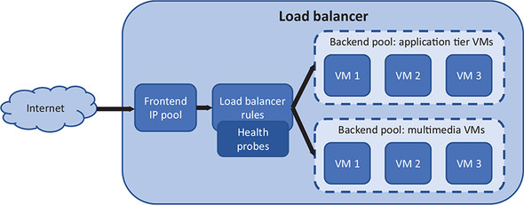
Figure 8.1. Traffic from the internet enters the load balancer through a public IP address that’s attached to a frontend IP pool. The traffic is processed by load-balancer rules that determine how and where the traffic should be forwarded. Health probes attached to the rules ensure that traffic is only distributed to healthy nodes. A backend pool of virtual NICs connected to VMs then receives the traffic distributed by the load-balancer rules.

A load balancer consists of a few main components:
- Frontend IP pool—Entry point to the load balancer. To allow access from the internet, a public IP address can be attached to the frontend IP pool. Private IP addresses can be attached for internal load balancers.
- Health probes—Monitor the status of attached VMs. To make sure traffic is only distributed to healthy and responsive VMs, checks are performed on a regular basis to confirm that a VM correctly responds to traffic.
- Load-balancer rules—Distribute the traffic to VMs. Each incoming packet is compared against the rules, which define incoming protocols and ports, and then distributed across a set of associated VMs. If no rules match the incoming traffic, the traffic is dropped.
- Network Address Translation (NAT) rules—Can route traffic directly to specific VMs. For example, if you want to provide remote access via SSH or RDP, you can define NAT rules to forward traffic from an external port to a single VM.
- Backend IP pool—Where the VMs that run your application are attached. Load-balancer rules are associated with backend pools. You can create different backend pools for different parts of your applications.
Azure load balancers can work at the network layer or the application layer. This chapter focuses on the regular Azure load balancer, which works at the network layer (layer 4, or Transport protocol). At this layer, the traffic is examined and distributed, but the load balancer has no context of what the traffic means or the applications that you run.
Azure Application Gateway is a load balancer that works at the application layer (layer 7). Application Gateway gains insight into the application that runs on the VM and can manage the traffic flows in more advanced ways. One major benefit of Application Gateway is the ability to handle encrypted, HTTPS web traffic.
When you load-balance websites with SSL certificates, you can offload the process that verifies and decrypts the traffic from the web servers. On websites with a lot of SSL traffic, the process to verify and decrypt the traffic can consume a large portion of compute time on the VMs or web apps. Application Gateway can verify and decrypt the traffic, pass the pure web request to the web servers, and then reencrypt the traffic received from the web servers and return it to the customer.
Application Gateway offers some other more advanced load-balancer features, such as the ability to distribute traffic across any IP endpoint rather than just an Azure VM. As you build applications that use more than VMs, these advanced distribution rules may be of use to you. The same core concepts apply as with a regular load balancer, which is what we focus on in this chapter so that you understand how it all works in Azure.
8.1.1. Creating a frontend IP pool
In previous chapters, you created VMs that had a public IP address assigned directly to them. You used this public IP address to then access the VM with a remote connection such as SSH or RDP, or used a web browser to access a website that ran on the VM. When you use a load balancer, you no longer connect straight to the VMs. Instead, to allow traffic to reach your load balancer and be distributed to your VMs, one or more IP addresses must be assigned to the external interface of a load balancer.
Load balancers can operate in one of two different modes:
- Internet load balancer—Has one or more public IP addresses connected to the frontend IP pool. An internet load balancer directly receives traffic from the internet and distributes it to backend VMs. A common example is for frontend web servers that customers directly access over the internet.
- Internal load balancer—Has one or more private IP addresses connected to the frontend IP pool. An internal load balancer works inside an Azure virtual network, such as for backend database VMs. You typically don’t expose backend databases or application tiers to the outside world. Instead, a set of frontend web servers connects to an internal load balancer that distributes the traffic without any direct public access. Figure 8.2 shows how an internal load balancer can distribute traffic to backend VMs that are behind a public-facing load balancer and frontend web VMs.
Figure 8.2. An internet load balancer may be used to distribute traffic to frontend VMs that run your website, which then connect to an internal load balancer to distribute traffic to a database tier of VMs. The internal load balancer isn’t publicly accessible and can only be accessed by the frontend VMs within the Azure virtual network.

The mode for your load balancer doesn’t change the behavior of the frontend IP pool. You assign one or more IP addresses that are used when access to the load balancer is requested. Both IPv4 and IPv6 addresses can be configured for the frontend IP pool. This allows you to configure end-to-end IPv6 communications between customers and your VMs as the traffic flows in and out of the load balancer.
To understand how the load-balancer components work together, complete the following steps to create a load balancer and frontend IP pool.
1. Open the Azure portal, and select the Cloud Shell icon at the top of the dashboard.
2. Create a resource group with az group create. Specify a resource group name, such as azuremolchapter8, and a location:
az group create --name azuremolchapter8 --location westeurope
As you continue to build on the previous chapter and want to use availability zones, take care with the region you select, to make sure availability zone support is available.
3. Create a public IP address with az network public-ip create. In chapter 7, you learned that availability zones provide redundancy to network resources, so create a standard, zone-redundant public IP address. Specify a name, such as publicip:
az network public-ip create
--resource-group azuremolchapter8
--name publicip
--sku standardTo create an IPv6 public IP address, you can add --version IPv6 to the preceding command. For these exercises, you can use IPv4 addresses.
4. Create the load balancer and assign the public IP address to the frontend IP pool. To add the public IP address, specify the --public-ip-address parameter. If you wanted to create an internal load balancer, you’d instead use the --private-ip-address parameter. As with the public IP address, create a standard, zone-redundant load balancer that works across availability zones:
az network lb create
--resource-group azuremolchapter8
--name loadbalancer
--public-ip-address publicip
--frontend-ip-name frontendpool
--backend-pool-name backendpool
--sku standardWe dive into what the backend pool is in a few minutes.
8.1.2. Creating and configuring health probes
If one of the VMs that run your application has a problem, do you think the load balancer should continue to distribute traffic to that VM? A customer who tries to access your pizza store may get directed to that VM and be unable to order any food! A load balancer monitors the status of the VMs and can remove VMs that have issues. The load balancer continues to monitor the health, and adds the VM back into the pool for traffic distribution when the VM is shown to respond correctly again.
A health probe can work in a couple of different modes:
- Port-based—The load balancer checks for a VM response on a specific port and protocol, such as TCP port 80. As long as the VM responds
to the health probe on TCP port 80, the VM remains in the load-balancer traffic distribution. Otherwise, the VM is removed
from the load-balancer traffic distribution, as shown in figure 8.3. This mode doesn’t guarantee that the VM serves the traffic as expected, only that the network connectivity and destination
service returns a response.
Figure 8.3. A port-based load-balancer health probe checks for a VM response on a defined port and protocol. If the VM doesn’t respond within the given threshold, the VM is removed from the load-balancer traffic distribution. When the VM starts to respond correctly again, the health probe detects the change and adds the VM back into the load-balancer traffic distribution.

- HTTP path-based—A custom page, such as health.html, is written and placed on each VM. This custom health check can be used to verify access to an image store or database connection. In this mode, the VM only remains in the load-balancer traffic distribution when the health-check page returns an HTTP code 200 response, as shown in figure 8.4. With a port-based health probe, the actual web server may run but have no database connection. With a custom health-check page, the load balancer can confirm that the VM is able to serve real traffic to the customer.
Figure 8.4. A VM that runs a web server and has a custom health.html page remains in the load-balancer traffic distribution provided that the health probe receives an HTTP code 200 (OK) response. If the web server process encounters a problem and can’t return requested pages, they’re removed from the load-balancer traffic distribution. This provides a more thorough check of the web server state than port-based health probes.

Additional work is required to create the custom health-check page, but the improved customer experience is worthwhile. The health-check page doesn’t have to be complicated. It could be a basic HTML page that’s used to confirm that the web server itself can serve pages. Without the health-check page, if the web server process has a problem, the VM would still be available on TCP port 80, so the port-based health probe would believe the VM to be healthy. An HTTP path-based health probe requires the web server to correctly return an HTTP response. If the web server process hangs or has failed, an HTTP response isn’t sent, so the VM is removed from the load-balancer traffic distribution.
How often the health probe checks the VM, and what the response is, can also be configured through two parameters:
- Interval—Defines how frequently the health probe checks the status of the VM. By default, the health probe checks the status every 15 seconds.
- Threshold—Defines how many consecutive response failures the health probe receives before the VM is removed from the load-balancer traffic distribution. By default, the health probe tolerates two consecutive failures before the VM is removed the load-balancer traffic distribution.
To create a health probe for your load balancer, as you just saw in figure 8.4, complete the following steps.
1. Open the Azure portal, and select the Cloud Shell icon at the top of the dashboard.
2. Specify a name for the health probe, such as healthprobe. To set up the health probe for a web server, specify HTTP port 80, and then define a custom health-check page at health.html. Later in the chapter, you create this health-check page on your VMs. To show how the interval and threshold for the health-probe response can be configured, define an interval of 10 seconds and a threshold of three consecutive failures:
az network lb probe create
--resource-group azuremolchapter8
--lb-name loadbalancer
--name healthprobe
--protocol http
--port 80
--path health.html
--interval 10
--threshold 3
After the health probe is created, how do you now make it check the status of your VMs? Health probes are associated with load-balancer rules. The same health probe can be used with multiple different load-balancer rules. Remember chapter 5, where you created network security groups (NSGs) and rules? Those NSGs can be associated with multiple different VMs or virtual network subnets. A similar one-to-many relationship applies to the health probes. Let’s see how to put your health probe to work and create load-balancer rules.
8.1.3. Defining traffic distribution with load-balancer rules
When traffic is directed through the load balancer to the backend VMs, you can define what conditions cause the user to be directed to the same VM. You may want the user to retain a connection to the same VM for the duration of a single session, or allow them to return and maintain their VM affinity based on the source IP address. Figure 8.5 shows an example of the default session affinity mode.
Figure 8.5. With session affinity mode, the user connects to the same backend VM only for the duration of their session.

In session affinity mode, the flow of traffic is handled by a 5-tuple hash that uses the source IP address, source port, destination IP address, destination port, and protocol type. Basically, for each request a user makes to your web server on TCP port 80, they’re directed to the same backend VM for the duration of that session.
What happens if the customer closes their browser session? The next time they connect, a new session is started. Because the load balancer distributes traffic across all healthy VMs in the backend IP pool, it’s possible that the user connects to the same VM again; but the more VMs you have in the backend IP pool, the greater the chance that the user connects to a different VM.
As the application owner and developer, there may be scenarios where you may want the user to connect to the same VM as before when they start another session. For example, if your application handles file transfers, or uses UDP rather than TCP, you likely want the same VM to continue to process their requests. In these scenarios, you can configure the load-balancer rules for source IP affinity. Figure 8.6 shows an example of source IP affinity mode.
Figure 8.6. When you configure the load-balancer rules to use source IP affinity mode, the user can close and then start a new session but continue to connect to the same backend VM. Source IP affinity mode can use a 2-tuple hash that uses the source and destination IP address, or a 3-tuple hash that also uses the protocol.

1. Open the Azure portal, and select the Cloud Shell icon at the top of the dashboard.
2. To create a load-balancer rule, specify a name for the rule, such as httprule. Provide the external port on which traffic is received and the internal port to distribute traffic to. In this basic example, traffic is received on port 80 and then distributed on port 80:
az network lb rule create
--resource-group azuremolchapter8
--lb-name loadbalancer
--name httprule
--protocol tcp
--frontend-port 80
--backend-port 80
--frontend-ip-name frontendpool
--backend-pool-name backendpool
--probe-name healthprobeIf you run multiple websites on a VM that responds on different ports, a given rule could direct traffic to a specific website on the VM.
8.1.4. Routing direct traffic with Network Address Translation rules
The load-balancer rules distribute traffic across the backend pools of VMs, so there’s no guarantee that you can connect to a given VM for maintenance or management purposes. How can you connect to a specific VM that’s behind a load balancer? One final part of the load-balancer configuration to look at are Network Address Translation (NAT) rules. These rules let you control the flow of specific traffic to direct it to a single VM. Figure 8.7 shows how NAT rules forward specific traffic to individual VMs.
Figure 8.7. Traffic in the load balancer is processed by NAT rules. If a protocol and port match a rule, the traffic is then forwarded to the defined backend VM. No health probes are attached, so the load balancer doesn’t check whether the VM is able to respond before it forwards the traffic. The traffic leaves the load balancer and is then processed by NSG rules. If the traffic is permitted, it’s passed to the VM.

NAT rules work alongside NSG rules. The VM can receive the traffic only if there’s a NSG rule that allows the same traffic as the load-balancer NAT rule.
Why might you create NAT rules? What if you want to use SSH or RDP to connect to a specific VM, or use management tools to connect to a backend database server? If the load balancer distributes traffic across the backend VMs, you’d have try to connect again and again and again, and you still might not connect to the desired VM.
We dive into some security topics in part 3 of the book, but security should be an ever-present consideration as you build and run applications in Azure. Security shouldn’t be something you add later. With the rise of cloud computing and disposable VMs and web apps, it’s easy to overlook some basic security best practices. Especially if you work in Azure as part of a wider enterprise subscription, make sure any resources you create don’t accidentally provide a way for attackers to gain access to your infrastructure.
What kind of things are bad? Well, some of things you’ve done already in this book! Remote management ports for SSH and RDP shouldn’t be opened to the public internet as you’ve done, or at the very least you should restrict access to being from a specific IP address range.
The best practice would be to create one secured VM that has remote management available. As needed, you connect to this one, secured VM, and then connect over the internal Azure virtual network to additional VMs. You used this basic jump-box VM approach in chapter 5. This approach minimizes the attack footprint and reduces the need for NSG rules and load-balancer NAT rules. Chapter 16 discusses Azure Security Center and how you can dynamically request and open remote-management ports for a specific time period, which is the best of both worlds.
Even if you work in a private Azure subscription that has no connectivity to other Azure subscriptions at school or work, try to minimize how much remote connectivity you provide.
To create a load balancer NAT rule, complete the following steps.
1. Open the Azure portal, and select the Cloud Shell icon at the top of the dashboard.
2. To create a load-balancer NAT rule, define a name, such as natrulessh, and the frontend IP pool to use. The NAT rule examines traffic on a given protocol and port, such as TCP port 50001. When there’s a rule match, the traffic is forwarded to backend port 22:
az network lb inbound-nat-rule create
--resource-group azuremolchapter8
--lb-name loadbalancer
--name natrulessh
--protocol tcp
--frontend-port 50001
--backend-port 22
--frontend-ip-name frontendpool
3. At this point, you’ve created a basic load balancer. Examine how the load-balancer components have come together:
az network lb show
--resource-group azuremolchapter8
--name loadbalancer
A public IP address has been assigned to the frontend IP pool, and you created a health probe to check the status on a custom health page for a web server. A load-balancer rule was created to distribute web traffic from your customers to a backend pool, and uses the health probe. You also have a load-balancer NAT rule that permits SSH traffic. But there are no VMs to receive that traffic yet. Your pizza store customers are hungry, so let’s create some VMs that can run your web application and to which the load balancer can distribute traffic!
8.1.5. Assigning groups of VMs to backend pools
The final section of the load balancer defines backend pools that include one or more VMs. These backend pools contain VMs that run the same application components, which allows the load balancer to distribute traffic to a given backend pool and trust that any VM in that pool can correctly respond to the customer request. Figure 8.8 details how the backend pools logically group together VMs that run the same applications.
Figure 8.8. One or more backend pools can be created in a load balancer. Each backend pool contains one or more VMs that run the same application component. In this example, one backend pool contains VMs that run the web application tier, and another backend pool contains the VMs that serve multimedia, such as images and video.
You create and use a load balancer with VMs, but everything works at the virtual network level. The frontend IP pool uses public or private IP addresses. The health probe looks at responses on a given port or protocol. Even when an HTTP probe is used, the load balancer looks for a positive network response. Load-balancer rules focus on how to distribute traffic from an external port in the frontend pool to a port on the backend pool.
When you assign VMs to the backend pool that receive traffic distributed by the load balancer, it’s the virtual NIC that connects to the load balancer. The VM happens to attach to the virtual NIC. Think back to chapter 5, and this separation of VMs and virtual NIC makes sense in terms of how resources are managed. NSG rules control what traffic is permitted to flow to the VM, but they’re applied to a virtual network subnet or virtual NIC, not the VM.
What does this mean for how you configure backend IP pools? You must create the rest of your virtual network resources before you can connect a VM to the load balancer. The steps to create the network resources should be a recap of what you learned a few chapters ago, so let’s see how much you remember!
To create the additional network resources, as shown in figure 8.9, complete the following steps.
1. Open the Azure portal, and select the Cloud Shell icon at the top of the dashboard.
2. Create a virtual network and subnet:
az network vnet create
--resource-group azuremolchapter8
--name vnetmol
--address-prefixes 10.0.0.0/16
--subnet-name subnetmol
--subnet-prefix 10.0.1.0/24In practice, there’s a good chance that these network resources already exist. These are also the same names and IP address ranges you used in chapter 5. You should clean up Azure resources at the end of each chapter, so such reuse of IP ranges shouldn’t be a problem. Just be aware that you typically won’t create a virtual network and subnet every time you create a load balancer. Rather, you can use the existing virtual network resources that are already in place.
3. Create an NSG:
az network nsg create
--resource-group azuremolchapter8
--name webnsgFigure 8.9. To prepare the virtual network, in this exercise you create a network, a subnet, and virtual NICs that are protected by a NSG. Rules attached to the NSG allow HTTP and SSH traffic.

4. Create an NSG rule that allows traffic from TCP port 80 to reach your VMs. This rule is needed for the web server VMs to receive and respond to customer traffic:
az network nsg rule create
--resource-group azuremolchapter8
--nsg-name webnsg
--name allowhttp
--priority 100
--protocol tcp
--destination-port-range 80
--access allow
5. Add another rule to allow SSH traffic for remote management. This NSG rule works with the load-balancer NAT rule created in the preceding section for one of your VMs:
az network nsg rule create
--resource-group azuremolchapter8
--nsg-name webnsg
--name allowssh
--priority 101
--protocol tcp
--destination-port-range 22
--access allow
6. Associate the NSG with the subnet created in step 2. The NSG rules are applied to all VMs that connect to this subnet:
az network vnet subnet update
--resource-group azuremolchapter8
--vnet-name vnetmol
--name subnetmol
--network-security-group webnsg
7. The load balancer works with virtual NICs, so create two virtual NICs and connect them to the virtual network subnet. Also specify the load-balancer name and backend address pool that the virtual NICs connect to. The load-balancer NAT rule is only attached to this first virtual NIC that’s created:
az network nic create
--resource-group azuremolchapter8
--name webnic1
--vnet-name vnetmol
--subnet subnetmol
--lb-name loadbalancer
--lb-address-pools backendpool
--lb-inbound-nat-rules natrulessh
8. Create the second NIC in the same way, minus the load-balancer NAT rule:
az network nic create
--resource-group azuremolchapter8
--name webnic2
--vnet-name vnetmol
--subnet subnetmol
--lb-name loadbalancer
--lb-address-pools backendpool
8.2. Creating and configuring VMs with the load balancer
Let’s pause and explore what you’ve now created. Figure 8.10 shows the big picture of what your network resources and load balancer look like. Notice how integrated these resources are. The load balancer can’t exist by itself. Virtual NICs must be connected to the load balancer for any traffic to be distributed. Those virtual NICs require a virtual network and subnet and should ideally be protected by an NSG. The VMs that then run your application have almost nothing to do with the steps to create and configure the load balancer!
Figure 8.10. No VMs have been created here—the load-balancer configuration deals with virtual network resources. There’s a tight relationship between the load balancer and virtual network resources.

You’ve created a lot of network resources and configured multiple parts of the load balancer. The public IP address and load balancer were created in an availability zone as zone-redundant resources, so let’s create two VMs across different zones to reinforce how availability zones enhance the high availability of your applications.
If you use availability sets rather than availability zones, this is where you first create an availability set and then add your VMs to it. The Azure platform then distributes the VMs across the fault and update domains. You want to maximize the use of Azure high availability for your pizza store, so use availability zones.
1. Create the first VM, and assign it to an availability zone with --zone 1. Attach the first virtual NIC created in the preceding exercise with --nics webnic1. Remember, the load balancer only knows about the virtual NIC. A VM just happens to be connected to that virtual NIC:
az vm create
--resource-group azuremolchapter8
--name webvm1
--image ubuntults
--size Standard_B1ms
--admin-username azuremol
--generate-ssh-keys
--zone 1
--nics webnic1
2. Create the second VM, and assign it to availability zone 2. Attach the second virtual NIC you created earlier, using --nics webnic2:
az vm create
--resource-group azuremolchapter8
--name webvm2
--image ubuntults
--size Standard_B1ms
--admin-username azuremol
--generate-ssh-keys
--zone 2
--nics webnic2
8.2.1. Connecting to VMs and seeing the load balancer in action
To see the load balancer in action, you need to install a basic web server, as you did in chapter 2. You can also try out the load-balancer NAT rule. Can you start to see how all these components in Azure are related and build on each other?
To install a web server on your VMs, complete the following steps.
1. Open the Azure portal, and select the Cloud Shell icon at the top of the dashboard.
2. In chapter 5, we discussed the SSH agent. The SSH agent allows you to pass an SSH key from one VM to the next. Only VM1 has a load balancer NAT rule, so you need to use the agent to connect to VM2.
Start the SSH agent, and add your SSH key so that you can connect to both VMs:
3. Obtain the public IP address attached to the load-balancer frontend IP pool. This is the only way for traffic to route through the VMs:
az network public-ip show
--resource-group azuremolchapter8
--name publicip
--query ipAddress
--output tsv
4. SSH to VM 1. Specify the public IP address of the load balancer and the port that was used with the load-balancer NAT rule, such as 50001. The -A parameter uses the SSH agent to pass through your SSH keys:
ssh -A azuremol@ipAddress -p 50001
5. In chapter 2, you used apt-get to install the entire LAMP stack that included the Apache web server. Let’s see something a little different from the Apache web server with the standalone but powerful NGINX web server. On a Windows VM, this is typically where you’d install IIS:
6. In the GitHub samples repo that you’ve used in previous chapters, there’s a basic HTML web page and a health-check page for the load-balancer health probe. Clone these samples to the VM:
git clone https://github.com/fouldsy/azure-mol-samples.git
7. Copy the sample HTML page and health-check to the web server directory:
sudo cp azure-mol-samples/8/webvm1/* /var/www/html/
8. Repeat all this for the second VM. Remember the SSH agent? You should be able to SSH from VM 1 to VM 2 on the internal, private IP address:
Install the Nginx web server:
Clone the GitHub samples to the VM:
git clone https://github.com/fouldsy/azure-mol-samples.git
9. And copy the sample HTML page and health check to the web server directory:
sudo cp azure-mol-samples/8/webvm2/* /var/www/html/
Open a web browser, and connect to the public IP address of your load balancer. The basic web page loads and shows that your pizza store now has redundant VMs in availability zones that run behind a load balancer, as shown in figure 8.11! You may need to force-refresh your web browser to see that both VM 1 and VM2 respond as the load balancer distributes traffic between them.
Figure 8.11. When you open the public IP address of the load balancer in a web browser, traffic is distributed to one of the VMs that run your basic website. The load-balancer health probe uses the health.html page to confirm the web server responses with an HTTP code 200 (OK). The VM is then available as part of the load-balancer traffic distribution.

8.3. Lab: Viewing templates of existing deployments
This chapter ties together what you learned in multiple previous chapters. You created network resources, as in chapter 5. You made the load balancer and VMs highly available with availability zones, as in chapter 7. And a web server was installed and sample files deployed, as in chapter 2. Your pizza store has come a long way from the basic web page on a single VM at the start of the book!
To tie in one more theme from a previous chapter, in this lab I want you to explore all the resources that make up the load balancer. To do this, you look at the Resource Manager template, as you learned about in chapter 6. The goal of this lab is to see how a single template can create and configure what’s taken many pages and multiple CLI commands. And trust me, it would take even more PowerShell commands! Follow these steps:
1. Open the Azure portal. Browse to and select Resource Group from the navigation bar at left in the portal. Choose your resource group, such as azuremolchapter8.
2. Choose Automation Script from the bar at left, as shown in figure 8.12.
Figure 8.12. In the Azure portal, select your load-balancer resource group and view the Resource Manager template.

3. To see the relevant part of the template, select each of the resources shown in the list. Take a few minutes to explore this template and see how all the resources and components that you configured in the Azure CLI are present.
A template makes it a lot easier to deploy a highly available, redundant, load-balanced application environment. You can change the load balancer’s name, rules, and distribution mode, and let the template deploy and configure the entire application environment for you.
Don’t forget to delete this resource group to make the most of your free Azure credits!