URDF is an XML format specifically defined to represent robot models down to their component level. These URDF files can become long and cumbersome on complex robot systems. Xacro (XML Macros) is an XML macro language created to make these robot description files easier to read and maintain. Xacro helps you reduce the duplication of information within the file.
For our first robot model, we will build a URDF file for a two-wheeled differential drive robot. The model will be created incrementally, and we will view the results at each step in rviz. When our simple two-wheeled robot is complete, we will add Gazebo formatting and view the model in Gazebo. In Chapter 5, Creating Your First Robot Arm (in Simulation), we will expand our knowledge of URDF files and build a simple robot arm model using the Xacro notation.
Note
Downloading the ros_robotics code
You can download the example code files and other support material for this book from www.PacktPub.com.
If you download the ros_robotics package from the Packt website, replace the entire ~/catkin_ws/src/ros_robotics directory with the downloaded package. Instead, if you plan to enter the code from this book, begin by creating a /urdf directory under your ros_robotics package directory:
$ cd ~/catkin_ws/src/ros_robotics
$ mkdir urdf
$ cd urdf
Two basic URDF components are used to define a tree structure that describes a robot model. The link component describes a rigid body by its physical properties (dimensions, position of its origin, color, and so on). Links are connected together by joint components. Joint components describe the kinematic and dynamic properties of the connection (that is, links connected, types of joint, axis of rotation, amount of friction and damping, and so on). The URDF description is a set of these link elements and a set of the joint elements connecting the links together.
The first component of our robot is a simple chassis box. The downloaded dd_robot.urdf file contains the code for this exercise. Alternately, you can enter the code portion using your favorite editor and save the file as dd_robot.urdf to your ~/catkin_ws/src/ros_robotics/urdf directory:
<?xml version='1.0'?>
<robot name="dd_robot">

  <!-- Base Link -->
  <link name="base_link">
    <visual>
      <origin xyz="0 0 0" rpy="0 0 0" />
      <geometry>
          <box size="0.5 0.5 0.25"/>
      </geometry>
    </visual>
  </link>

</robot>This XML code defines a robot labeled dd_robot that has one link (also known as part) whose visual component is a box 0.5 meters long, 0.5 meters wide, and 0.25 meters tall. The box is centered at the origin (0, 0, 0) of the environment with no rotation in the roll, pitch, or yaw (rpy) axes. The link has been labeled base_link, and our model will use this box as the link on which our other links are defined. (A base_link link should be identified as the URDF root link to create the beginning of the robot's kinematic chain.) This XML is quite a bit of code for a simple box, but it will soon become even more complicated.
Roslaunch is a ROS tool that makes it easy to launch multiple ROS nodes as well as set parameters on the ROS Parameter Server. Roslaunch configuration files are written in XML and typically end in a .launch extension. In a distributed environment, the .launch files also indicate the processor the nodes should run on.
To use roslaunch for our URDF file, you will need to use one of the following ways:
- Download the
ddrobot_rviz.launchfile from theros_robotics/launchdirectory from this book's website - Create a
launchdirectory under theros_roboticspackage and create theddrobot_rviz.launchfile from the following XML code:<launch> <!-- values passed by command line input --> <arg name="model" /> <arg name="gui" default="False" /> <!-- set these parameters on Parameter Server --> <param name="robot_description" textfile="$(find ros_robotics)/urdf/$(arg model)" /> <param name="use_gui" value="$(arg gui)"/> <!-- Start 3 nodes: joint_state_publisher, robot_state_publisher and rviz --> <node name="joint_state_publisher" pkg="joint_state_publisher" type="joint_state_publisher" /> <node name="robot_state_publisher" pkg="robot_state_publisher" type="state_publisher" /> <node name="rviz" pkg="rviz" type="rviz" args="-d $(find ros_robotics)/urdf.rviz" required="true" /> </launch>
This roslaunch file performs the following:
- Loads the model specified in the command line into the Parameter Server.
- Starts nodes that publish the JointState and transforms (discussed later in this chapter).
- Starts rviz with a configuration file (
urdf.rviz). It is important to use theurdf.rvizfile that came with the book example code or save your ownurdf.rvizfile from rviz to be used with this launch file.
Type the following command to see the robot model in rviz:
$ roslaunch ros_robotics ddrobot_rviz.launch model:=dd_robot.urdf
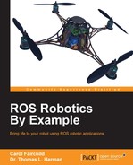
At this point, your rviz screen should resemble one of the following two screenshots. Look carefully for a visual representation of your dd_robot box in the main screen and examine it under the Displays panel to decide how to proceed. Does your rviz screen look like the following screenshot:
Rviz screen without urdf.rviz file
If your rviz screen looks like the the preceding screenshot with no box on the main screen and no Robot Model or TF under the Displays panel, then perform the following three steps in any order:
- Select the Add button under the Displays panel and add RobotModel
- Select the Add button under the Displays panel and add TF
- Select the field next to Fixed Frame (under Global Options), which in the preceding screenshot says map, and type in
base_link
(The preceding screenshot shows the Add menu with the RobotModel selection highlighted.) When all the three steps are completed, your rviz screen will look similar to the following screenshot.
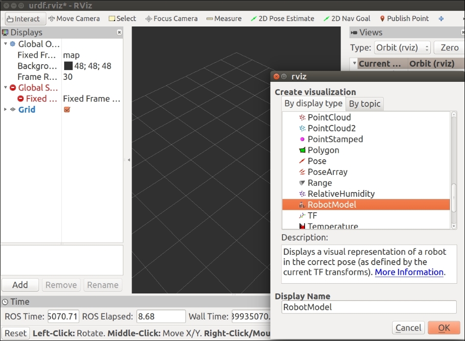
For the users who copied the urdf.rviz file from the book example code, the rviz screen will come up and and look like this:
dd_robot.urdf in rviz
Things to note:
- The fixed frame is a transform frame where the center (origin) of the grid is located.
- In URDF, the
<origin>tag defines the reference frame of the visual element with respect to the reference frame of the link. Indd_robot.urdf, the visual element (the box) has its origin at the center of its geometry by default. Half of the box is above the grid plane and half is below. - The rviz display configuration has been changed to remove the View and Time displays. This configuration is defined in the
urdf.rvizfile that comes with the book's example code (refer to the.launchfile commands). - The RobotModel and TF displays have been added under the Displays panel. Under RobotModel, notice the following:
- Robot description:
robot_descriptionis the name of the ROS parameter where the URDF file is stored on the Parameter Server. The description of the links and joints and how they are connected is stored here.
- Robot description:
Now, let's add shapes and links for wheels on our robot. When we add link elements to the URDF file, we must add joints to describe the relationship between the links. Joint elements define whether the joint is flexible (movable) or inflexible (fixed). For flexible joints, the URDF describes the kinematics and dynamics of the joint as well as its safety limits. In URDF, there are six possible joint types, which are as follows:
- Fixed: This is not really a joint because it cannot move. All degrees of freedom are locked. This type of joint does not require the axis, calibration, dynamics, limits, or safety controller.
- Revolute: This joint rotates around one axis and has a range specified by the upper and lower limits.
- Continuous: This is a continuous hinge joint that rotates around the axis and has no upper and lower limits.
- Prismatic: This is a sliding joint that slides along the axis and has a limited range specified by the upper and lower limits.
- Floating: This joint allows motion for all six degrees of freedom.
- Planar: This joint allows motion in a plane perpendicular to the axis.
For our robot wheels, we require continuous joints, which means that they can respond to any rotation angle from negative infinity to positive infinity. They are modeled like this so that they can rotate in both directions forever.
The downloaded dd_robot2.urdf file contains the XML code for this exercise. Alternately, you can enter the new code portion to your previous URDF file to create the two wheels (lines from the previous code have been left in or omitted and new code has been highlighted):
<?xml version='1.0'?>
<robot name="dd_robot">
  <!-- Base Link -->
  <link name="base_link">
  …
  </link>

  <!-- Right Wheel -->
  <link name="right_wheel">
    <visual>
      <origin xyz="0 0 0" rpy="1.570795 0 0" />
      <geometry>
          <cylinder length="0.1" radius="0.2" />
      </geometry>
    </visual>
  </link>
  <joint name="joint_right_wheel" type="continuous">
    <parent link="base_link"/>
    <child link="right_wheel"/>
    <origin xyz="0 -0.30 0" rpy="0 0 0" />
    <axis xyz="0 1 0" />
  </joint>

  <!-- Left Wheel -->
  <link name="left_wheel">
    <visual>
      <origin xyz="0 0 0" rpy="1.570795 0 0" />
      <geometry>
          <cylinder length="0.1" radius="0.2" />
      </geometry>
    </visual>
  </link>
  <joint name="joint_left_wheel" type="continuous">
    <parent link="base_link"/>
    <child link="left_wheel"/>
    <origin xyz="0 0.30 0" rpy="0 0 0" />
    <axis xyz="0 1 0" />
  </joint>
</robot>
Run your rviz roslaunch command:
$ roslaunch ros_robotics ddrobot_rviz.launch model:=dd_robot2.urdf
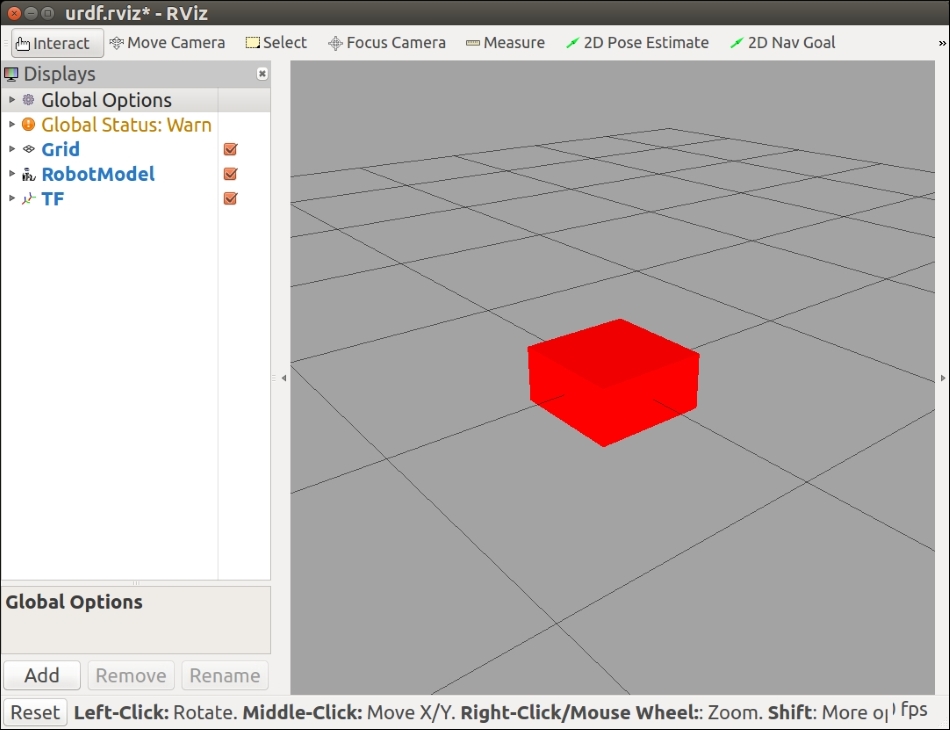
Rviz should come up and look like this:
dd_robot2.urdf in rviz
Things to note in the URDF:
- Each wheel is defined visually as a cylinder of radius
0.2meters and length of0.1meters. The wheel's visual origin defines where the center of the visual element should be, relative to its origin. Each wheel's origin is at (0,0,0) and is rotated by1.560795radians (= pi/2 = 90 degrees) about the x axis. - The joint is defined in terms of a parent and a child. The URDF file is ultimately a tree structure with one root link. The
base_linklink is our robot's root link with the wheel's position dependent on the base_link's position. - The wheel joint is defined in terms of the parent's reference frame. Therefore, the wheel's joint origin is
0.30meters in the x direction for the left wheel and-0.30meters for the right wheel. - The axis of rotation is specified by an
xyztriplet, indicating that the wheel's joint axis of rotation is around the y axis. - These
<joint>elements define the complete kinematic model of our robot.
In the next step, we will add a caster to the front of our robot in order to keep the robot chassis balanced. The castor will only be a visual element added to the chassis and not a joint. The caster will slide along the ground plane as the robot's wheels move.
The downloaded dd_robot3.urdf file contains the XML code for this exercise. Alternately, you can enter the new code portion to your previous URDF file(new code has been highlighted):
<?xml version='1.0'?>
<robot name="dd_robot">

  <!-- Base Link -->
  …
    <!-- Caster -->
    <visual name="caster">
      <origin xyz="0.2 0 -0.125" rpy="0 0 0" />
      <geometry>
        <sphere radius="0.05" />
      </geometry>
    </visual>

  </link>
  <!-- Right Wheel -->
  …
  <!-- Left Wheel -->
  …
</robot>
Run your rviz roslaunch command:
$ roslaunch ros_robotics ddrobot_rviz.launch model:=dd_robot3.urdf
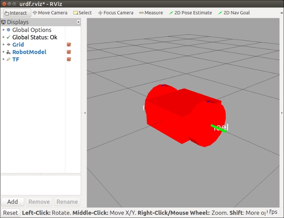
Rviz should come up and look like this:
dd_robot3.urdf in rviz
Things to note in the URDF file:
- The caster is defined visually as a sphere with a radius of
0.05meters. The center of the caster is0.2meters in the x direction and-0.125meters in the z direction with respect to the origin of thebase_link.
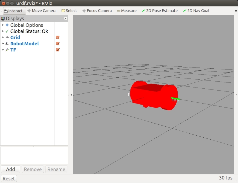
A completely red robot has parts that are not distinctive enough; we will add some color to our model.
The downloaded dd_robot4.urdf file contains the XML code for this exercise. Alternately, you can enter the new code portions to your previous URDF file (new code has been highlighted):
<?xml version='1.0'?>
<robot name="dd_robot">

  <!-- Base Link -->
  ...
      <material name="blue">
        <color rgba="0 0.5 1 1"/>
      </material>
    </visual>

    <!-- Caster -->
    …
  <!-- Right Wheel -->
  …
      <material name="black">
        <color rgba="0.05 0.05 0.05 1"/>
      </material>
     </visual>
 …
  <!-- Left Wheel -->
  …
      <material name="black"/>
    </visual>
  …
</robot>
Run your rviz roslaunch command:
$ roslaunch ros_robotics ddrobot_rviz.launch model:=dd_robot4.urdf
Rviz should look like the following screenshot:
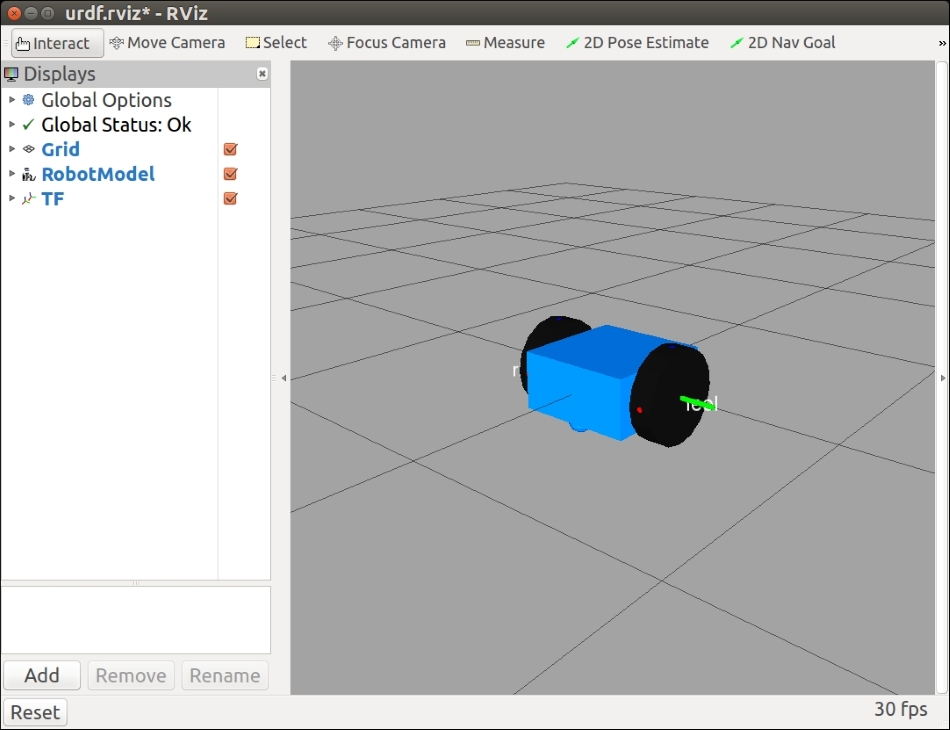
dd_robot4.urdf in rviz
Things to note in the URDF file:
- The
<material>tag can define<color>in terms of red/green/blue/alpha, each in the range of [0,1]. Alpha is the transparency level of the color. An alpha value of 1 is opaque and 0 is transparent. Once specified and labeled with a name, the material name can be reused without specifying the color values. (For example, note that the left wheel does not have a<color rgba>tag because it has been defined in the right wheel visual link.) - Although the book may show this picture in shades of gray, the chassis of the robot is now blue and the wheels are black.
Next, we will add the <collision> properties to each of our <link> elements. Even though we have defined the visual properties of the elements, Gazebo's collision detection engine uses the collision property to identify the boundaries of the object. If an object has complex visual properties (such as a mesh), a simplified collision property should be defined in order to improve the collision detection performance.
The downloaded dd_robot5.urdf file contains the XML code for this exercise. Alternately, you can enter the new code portions to your previous URDF file (new code has been highlighted):
<?xml version='1.0'?>
<robot name="dd_robot">

  <!-- Base Link -->
  …
    <!-- Base collision -->
    <collision>
      <origin xyz="0 0 0" rpy="0 0 0" />
      <geometry>
          <box size="0.5 0.5 0.25"/>
      </geometry>
    </collision>

    <!-- Caster -->
    …
    <!-- Caster collision -->
    <collision>
      <origin xyz="0.2 0 -0.125" rpy="0 0 0" />
      <geometry>
        <sphere radius="0.05" />
      </geometry>
    </collision>
  </link>

  <!-- Right Wheel -->
  …
    <!-- Right Wheel collision -->
    <collision>
      <origin xyz="0 0 0" rpy="1.570795 0 0" />
      <geometry>
          <cylinder length="0.1" radius="0.2" />
      </geometry>
    </collision>
  …

  <!-- Left Wheel -->
  …
    <!-- Left Wheel collision -->
    <collision>
      <origin xyz="0 0 0" rpy="1.570795 0 0" />
      <geometry>
          <cylinder length="0.1" radius="0.2" />
      </geometry>
    </collision>
</robot>
Adding the <collision> property does not change the visual model of the robot, and the rviz display will look the same as in the previous screenshot.
Now that we have the right and left wheel joints defined and we can see them clearly, we will bring up the GUI pop-up screen to control these joints. In the ddrobot_rviz.launch file, we start three ROS nodes: joint_state_publisher, robot_state_publisher, and rviz. The joint_state_publisher node finds all of the non-fixed joints and publishes a JointState message with all those joints defined. So far, the values in the JointState message have been constant, keeping the wheels from rotating. We bring up a GUI interface in rviz to change the value of each JointState and watch the wheels rotate.
Add the gui field to the rviz roslaunch command:
$ roslaunch ros_robotics ddrobot_rviz.launch model:=dd_robot5.urdf gui:=True
Rviz should look like the following screenshot:
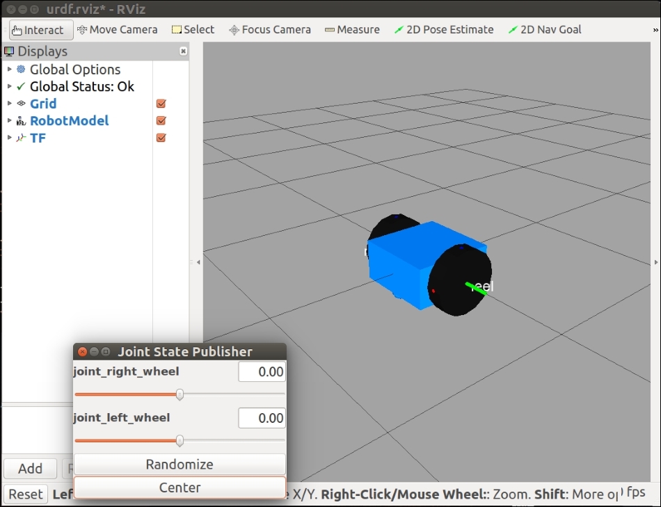
dd_robot5.urdf in rviz
- The joint positions in the window are sliders. The wheel joints are defined as continuous but this GUI limits each slider's value from –Pi to +Pi. Play with the sliders and see how the wheels move.
- The Randomize button will select a random value for both the joints.
- The Center button will move both the joints to the zero position. (Visually, the blue dot on both the wheels should be at the top).
A robotic system is made up of a collection of 3D coordinate frames for every component in the system. In our dd_robot model, there is a base coordinate frame and a frame for each wheel that relates back to the base coordinate frame. The model's coordinate frames are also related to the world coordinate frame of the 3D environment. The tf package is the central ROS package used to relate the coordinate frames of our robot to the 3D simulated environment (or a real robot to its real environment).
The robot_state_publisher node subscribes to the JointState message and publishes the state of the robot to the tf transform library. The tf transform library maintains the relationships between the coordinate frames of each component in the system over time. The robot_state_publisher node receives the robot's joint angles as inputs and computes and publishes the 3D poses of the robot links. Internally, the robot_state_publisher node uses a kinematic tree model of the robot built from its URDF. Once the robot's state gets published, it is available to all components in the system that also use tf.
With the additional physical properties of mass and inertia, our robot will be ready to be launched in the Gazebo simulator. These properties are needed by Gazebo's physics engine. Specifically, every <link> element that is being simulated needs an <inertial> tag.
The two sub-elements of the inertial element we will use are as follows:
<mass>: This is the weight defined in kilograms.<inertia>: This frame is a 3 x 3 rotational inertia matrix. Because this matrix is symmetrical, it can be represented by only six elements. The six highlighted elements are the six element<inertia>values. The other three values are not used.ixx
ixy
ixz
ixy
iyy
iyz
ixz
iyz
izz
Using Wikipedia's list of moment of inertia tensors (https://en.wikipedia.org/wiki/List_of_moments_of_inertia), which provides the equations for the inertia of simple geometric primitives, such as a cylinder, box, and sphere. We use these equations to compute the inertia values for the model's chassis, caster, and wheels.
Do not use inertia elements of zero (or almost zero) because real-time controllers can cause the robot model to collapse without warning, and all links will appear with their origins coinciding with the world origin.
The downloaded dd_robot6.urdf file contains the XML code for this exercise. Alternately, you can enter the new code portions in your previous URDF file (new code has been highlighted):
<?xml version='1.0'?>
<robot name="dd_robot">

  <!-- Base Link -->
  …
    <inertial>
      <mass value="5"/>
      <inertia ixx="0.13" ixy="0.0" ixz="0.0"
               iyy="0.21" iyz="0.0" izz="0.13"/>
    </inertial>

    <!-- Caster -->
    …
    <inertial>
      <mass value="0.5"/>
      <inertia ixx="0.0001" ixy="0.0" ixz="0.0"
               iyy="0.0001" iyz="0.0" izz="0.0001"/>
    </inertial>
  </link>

  <!-- Right Wheel -->
  …
    <inertial>
      <mass value="0.5"/>
      <inertia ixx="0.01"  ixy="0.0" ixz="0.0"
               iyy="0.005" iyz="0.0" izz="0.005"/>
    </inertial>
  …
  <!-- Left Wheel -->
  …
    <inertial>
      <mass value="0.5"/>
      <inertia ixx="0.01" ixy="0.0" ixz="0.0"
               iyy="0.005" iyz="0.0" izz="0.005"/>
    </inertial>
    …
</robot>
Adding the <inertial> property does not change the visual model of the robot, and the rviz display will look the same as the preceding screenshot.
ROS provides command-line tools that can help verify and visualize information about your URDF. We will try out these tools on our robot URDF but first the tools must be installed on your computer system. Type the following command:
$ sudo apt-get install liburdfdom-tools
check_urdf attempts to parse a URDF file description and either prints a description of the resulting kinematic chain or an error message:
$ check_urdf dd_robot6.urdf
The output of the preceding command is as follows:
robot name is: dd_robot
---------- Successfully Parsed XML ---------------
root Link: base_link has 2 child(ren)
 child(1): left_wheel
child(2): right_wheel
The
urdf_to_graphiz tool creates a graphviz diagram of a URDF file and a diagram in the .pdf format. Graphviz is an open source graph visualization software. To execute urdf_to_graphiz, type:
$urdf_to_graphiz dd_robot6.urdf
The output is as follows:
Created file dd_robot.gv
Created file dd_robot.pdf
The dd_robot.pdf file is shown as follows:
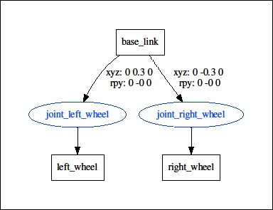
dd_robot.pdf
Now that we have a working URDF model of our two-wheeled robot, we are ready to launch it into Gazebo and move it around. First, we must make some modifications to our URDF file to add simulation-specific tags so that it properly works in Gazebo. Gazebo uses SDF, which is similar to URDF, but by adding specific Gazebo information, we can convert our dd_robot model file into an SDF-type format.