For the Kinect, our workstation computer requires us to run Protonect prior to using the kinect2_bridge software. If you have trouble launching the kinect2_bridge software, use the following command before you begin:
$ ./libfreenect2/build/bin/Protonect
Verify that Protonect shows color, depth, and IR images and that none of the screens are black. Be aware that Protonect has three optional parameters: cl (for OpenCL), gl (for OpenGL) or cpu (for CPU support). These options can be useful for testing the Kinect v2 operation.
If Protonect has successfully brought up the Kinect image, then press Ctrl + C to close this window. The kinect2_bridge and kinect2_viewer should then work properly until the system is restarted.
Next, we must determine how to identify our robots within the frame of the Kinect image.
For our Crazyflie and target location, we have prepared markers to uniquely identify them in our lab environment. For the Crazyflie, we have placed a lightweight green ball on top of its battery and attached it with a sticky mounting tab. For the target, we have placed a pink paper rectangle at the target location. The first step is to find a unique way to identify these markers and find their locations within the Kinect image.
OpenCV offers over 150 color conversion options for processing images. For object tracking, the simplest and recommended method is to convert the blue-green-red (BGR) image to hue-saturation and value (HSV). This is an easy and effective method for selecting an object of a desired color. An OpenCV tutorial on object tracking can be found at http://opencv-pythontutroals.readthedocs.org/en/latest/py_tutorials/py_imgproc/py_colorspaces/py_colorspaces.html.
A complete method for object tracking is described in the following sections.
The color of these identifiers will be used in our software to pinpoint the location of the quadrotor and target. First, we must determine the numerical values of the HSV components of their colors. This is done by grabbing an image of the marker with the Kinect and using the GNU Image Manipulator Program (GIMP) software on Ubuntu to classify the HSV numbers.
Start by running the kinect2_bridge launch file and kinect2_viewer; bring up an image of your Crazyflie and/or your target on your computer screen. For this exercise, these robots can be in the same view, or you can perform these steps one at a time for each of the markers. Use the Alt + Print Screen keys or your favorite screen-capture program to snap a picture of the scene and save it to a file. Click on the Dash tool in the Ubuntu Launcher and type in GIMP to find the GIMP application software.
After starting the GIMP software, open the image and select the following two options from the top menu bar:
- Under Tools, Select Color Picker (notice the cursor change to an eyedropper) under Tools
- Under Window, Select New Toolbox under Window
Move the eyedropper cursor to the center of the identifier (green ball in our case) and click on mouse button. This color will appear in the color rectangle at the bottom of the New Toolbox window. Click on this colored rectangle and the Change Foreground Color window will appear with the color marked with crosshairs in the color image on the left side. On the right side are the hue, saturation, value, red, green, and blue values that correspond to that color. The following screenshot illustrates the results of this process:

Using GIMP to find HSV numbers
For our green ball, the HSV numbers were H = 109, S = 62, and V = 49, as shown in the previous screenshot. These values apply to the scales for GIMP integer ranges of Hue (0 - 360), Saturation (0 - 100), and Value (0 - 100).
Now we must convert these values to the OpenCV integer ranges of Hue (0 - 179), Saturation (0 - 255), and Value (0 - 255). Therefore, our HSV numbers are computed as follows:
Hue: 109 / 2 ≈ 55
Saturation: 62 * 255 / 100 ≈ 158
Value: 49 * 255 / 100 ≈ 125
Now, to pick range values for the software, we will apply the following rules:
Hue: use range ± 10
Saturation: use range ± 50
Value: use range ± 50
Using these as guidelines, we arrive at the range values for our green ball as follows:
Hue: (45 - 65)
Saturation: (110 - 210)
Value: (75 - 175)
The HSV numbers for the pink rectangle target were H = 298, S = 28, and V = 96 when the target was directly facing the Kinect. Initially, we chose the following ranges in the code:
Hue: (139 - 159)
Saturation: (21 - 121)
Value: (240 - 255)
We modified these values later as we tested the tracking of these objects in the Kinect image viewer. The Saturation (or whiteness) value ranges from white (0) to full saturated color (100), and Value (or lightness) ranges from black (0) to the lightest color (100) in GIMP.
Tracking the target was especially tricky. As the target was placed in a horizontal position, the light reflecting off of the top of the target changed the Saturation and Value components of its HSV. It is extremely important to test the object detection capability from one side of the Kinect image to the other and for different orientations of the object. Selecting the appropriate range for HSV values is crucial to the success of the mission. For the target, we decreased the lower range of Saturation to improve target detection in our lighting conditions.
OpenCV is used to detect these identifiers in the Kinect image, and we use the following code to verify that we have captured the correct identifier for the green ball:
#!/usr/bin/env python
import cv2
import numpy

# read png image and convert the image to HSV
image = cv2.imread("<path>/<png filename>", cv2.CV_LOAD_IMAGE_COLOR)
hsv = cv2.cvtColor(image, cv2.COLOR_BGR2HSV)

# find green objects in the image
lower_green = numpy.array([45, 110, 75], numpy.uint8)
upper_green = numpy.array([65, 210, 255], numpy.uint8)
mask = cv2.inRange(hsv, lower_green, upper_green)

cv2.imwrite("hsv_mask.png", mask)
This code is contained in the view_mask.py file. The kinect2_viewer_green_ball.png file is provided with the code so that you can duplicate our steps and reproduce a file with the HSV mask of the green ball.
To briefly explain this code, we will examine the lines in relative groupings. First, the packages needed for this code are imported:
#!/usr/bin/env python
import cv2
import numpy
The cv2 package is the OpenCV 2.0 wrapper for Python and provides access to a variety of vision processing functions. The numpy package is an extension of Python that handles numerical manipulations for large multidimensional arrays and matrices.
The next section of code handles the reading of the image from a file and processing it for HSV:
image = cv2.imread("<path>/<png filename>", cv2.CV_LOAD_IMAGE_COLOR)
hsv = cv2.cvtColor(image, cv2.COLOR_BGR2HSV)
The first command loads the image from the file using the cv2.imread function. The first argument is the image file to be loaded, which can be any image file type. We are using .png files. The second argument for cv2.imread specifies to load the image as an RGB color image. In OpenCV, the RGB values are identified in reverse order as BGR. This loaded image is converted from BGR to HSV using the cv2 function cvtColor.
Next, two arrays are created to contain the lower bounds and the upper bounds of the HSV values for the green ball. The values in these arrays were identified and calculated in the previous section, Identifying markers in a color image. These arrays are used to find pixels in the image that fit within those bounds:
# find green objects in the image
lower_green = numpy.array([45, 110, 75], numpy.uint8)
upper_green = numpy.array([65, 210, 255], numpy.uint8)
mask = cv2.inRange(hsv, lower_green, upper_green)

cv2.imwrite("hsv_mask.png", mask)
As numpy array is created with unsigned integer values for the lower bounds of H, S, and V. A second array is created to contain the upper bounds for these elements. The cv2 function inRange performs the comparison of each pixel of the image to determine whether it falls within these bounds. If it does, a white pixel is placed in the mask image; otherwise, a black pixel is placed in the image. The last command imwrite stores the binary image to the hsv_mask.png file. The following image shows the resulting HSV mask image of the green ball:

HSV mask image of green ball.
This code is implemented in the detect_crazyflie.py and detect_target.py scripts described in the next sections.
Using Kinect to locate the position of the Crazyflie provides only a (pixel) location relative to the image frame of the Kinect. Relating this location to the world coordinate frame cannot be accurately accomplished.
Advanced camera systems, such as the VICON motion capture system, provide the object location in world coordinates. In a VICON system, it is possible to establish Crazyflie's position as (0, 0, 0) in x, y, and z and relate the movement in terms of meters. If you have this type of system available, check out Wolfgang Hoenig's ROS Crazyflie code at http://wiki.ros.org/crazyflie. The crazyflie_controller package provides simple navigation to goal using VICON. The crazyflie_demo package contains sample scripts and launch files to perform teleoperation, hovering, and waypoint navigation. The controller within our crazyflie_autonomous package was created based on concepts used in Mr. Hoenig's packages.
For our mission, the Python script detect_crazyflie.py creates the crazyflie_detector node to handle the process of identifying the location of the Crazyflie within the Kinect image frame and publishing its location. This node subscribes to three topics published by the kinect2 node specifying the qhd resolution (960 x 540). The code for subscribing to these topics is as follows:
rospy.wait_for_message('/kinect2/qhd/camera_info', CameraInfo)

rospy.Subscriber('/kinect2/qhd/camera_info', CameraInfo, self.camera_data, queue_size=1)
rospy.Subscriber('/kinect2/qhd/image_color_rect', Image, self.image_callback, queue_size=1)
rospy.Subscriber('/kinect2/qhd/image_depth_rect', Image, self.depth_callback, queue_size=1)
The rospy call to wait_for_message will assure that the kinect2 node is publishing topics. Then, the crazyflie_detector node will subscribe to the three topics: camera_info, image_color_rect, and image_depth_rect. The /kinect2/qhd/camera_info topic will contain a sensor_msgs/CameraInfo message that is processed by the callback function camera_data. The camera_data function will extract the camera height and width fields from the CameraInfo message and set parameters on the Parameter Server for camera_height and camera_width. For qhd resolution, these parameters are 540 and 960, respectively.
The /kinect2/qhd/image_color_rect and /kinect2/qhd/image_depth_rect topics subscribe to sensor_msgs/Image messages. For the rectified color Image message, the function image_callback is called to handle the image processing. The rectified depth Image message is processed by the depth_callback function. The message queue size is limited to one so that only the latest Image message will be processed.
The image_callback function processes the color image similar to the object detection method described in the Detecting and viewing markers with OpenCV section. The green objects in the image are detected, and a binary mask image is created. The cv2.morphologyEx function is called to first dilate and then erode the image with an 11 x 11 kernel. This process removes the small pixels within the white objects and the surrounding black background. More than one white object may be present in the binary image. The next step is to find all the objects and order them by size. The cv2 function findContours finds all the pixels within the contour objects in the binary image. A hierarchy of nested contours is created. A check is made to assure that there is at least one contour in this hierarchy, then the area of each of the contours is calculated. The largest contour area is selected as the green ball on top of Crazyflie.
Since we know that this object is round, the cv2 function minEnclosingCircle is used to find the object's center and radius. The horizontal center of the object is saved as cf_u, and the vertical center is saved as cf_v. The object center and radius values are used by the cv2.circle function to draw a blue circle outline around the object in the original color Image message. This image message is then displayed in a terminal window using the cv2.imshow function. The resulting image is shown in the following screenshot:
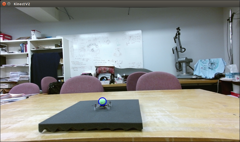
Crazyflie detected
When a /kinect2/qhd/image_depth_rect topic arrives, the depth_callback function will be called to process this sensor_msgs/Image message. For this rectified depth Image message, the cf_u and cf_v values will be used as the pixel coordinates to access the depth value, cf_d, at the center of the circle. Sometimes, an erroneous value is returned for the depth at this location. If the depth value returned is zero, the last depth value will be reused.
Next, the update_cf_transform function is called to publish the tf transform of Crazyflie. The cf_u, cf_v, and cf_d values are passed to this function to use as the x, y, and z values of Crazyflie's transform. A tf.TransformBroadcaster object is created to publish transforms from the crazyflie_detector node. The update_cf_tranform function uses the sendTransform function (from the tf package) for the transform broadcaster to publish a transform for the Crazyflie relative to the Kinect. Details of this transform are described in the next section.
Using ROS tf transforms to identify the location of the Crazyflie in an image frame is a variation of the concept of ROS tf. Typically, tf transforms relate the coordinate frame of a robot's component to the rest of its system and environment (world) in which it is operating. Tf keeps all the robot's coordinate frames in a tree-like structure that relates it to the world environment. In addition, these coordinate frames are tracked by tf with relation to time. Tf provides functions to transform from one coordinate frame to any other frame in the tf structure at a desired point in time. For more information on this implementation of tf, refer to the Understanding tf section in Chapter 6, Wobbling Arms using Joint Control.
For our mission, Crazyflie's tf transforms are limited to operations within the 2D image plane of the Kinect's color image and the third dimension of depth from the Kinect's depth image. Crazyflie's position with respect to the image's horizontal position u and its vertical position v are used to identify its location with respect to the color image frame. Its 3D position can be completed by accessing the depth value from the depth frame for the (v, u) location. These values are used as the x, y, z of Crazyflie's translation fields for the transform message. The
rotation fields are fixed with values to change the orientation of Crazyflie from the Kinect's camera orientation.
For the Kinect coordinate frame, the x axis is horizontal from the upper-left corner of the camera image to the right, the y axis is vertical from this same corner downward, and the z axis is from the front face of the camera out to the scene. The Kinect coordinate frame is represented in the following rviz image, using the convention of x (red), y (green), and z (blue). The position of this coordinate frame is at the origin of the Kinect and does not represent the location on the image frame:

tf coordinate frames in rviz
For Crazyflie, a rotation of this Kinect coordinate frame must be made to adhere to the ROS conventional orientation of x forward, y left, and z up standardized in REP 103 Coordinate Frame Conventions. Therefore, for rotation fields in Crazyflie's tf transform, values are fixed to the set of Euler angles:
- Roll of
-π/2 - Pitch of
0 - Yaw of
–π
These values are used to compute a quaternion with the tf.transformations.quaternion_from_euler function. The transform pose is published using the sendTransform function (from the tf package) as a transform from the kinect2_ir_optical_frame to the crazyflie/baselink. The kinect2_ir_optical_frame is the parent frame of crazyflie/baselink. A diagram of the tf frames broadcast for this mission is shown here:
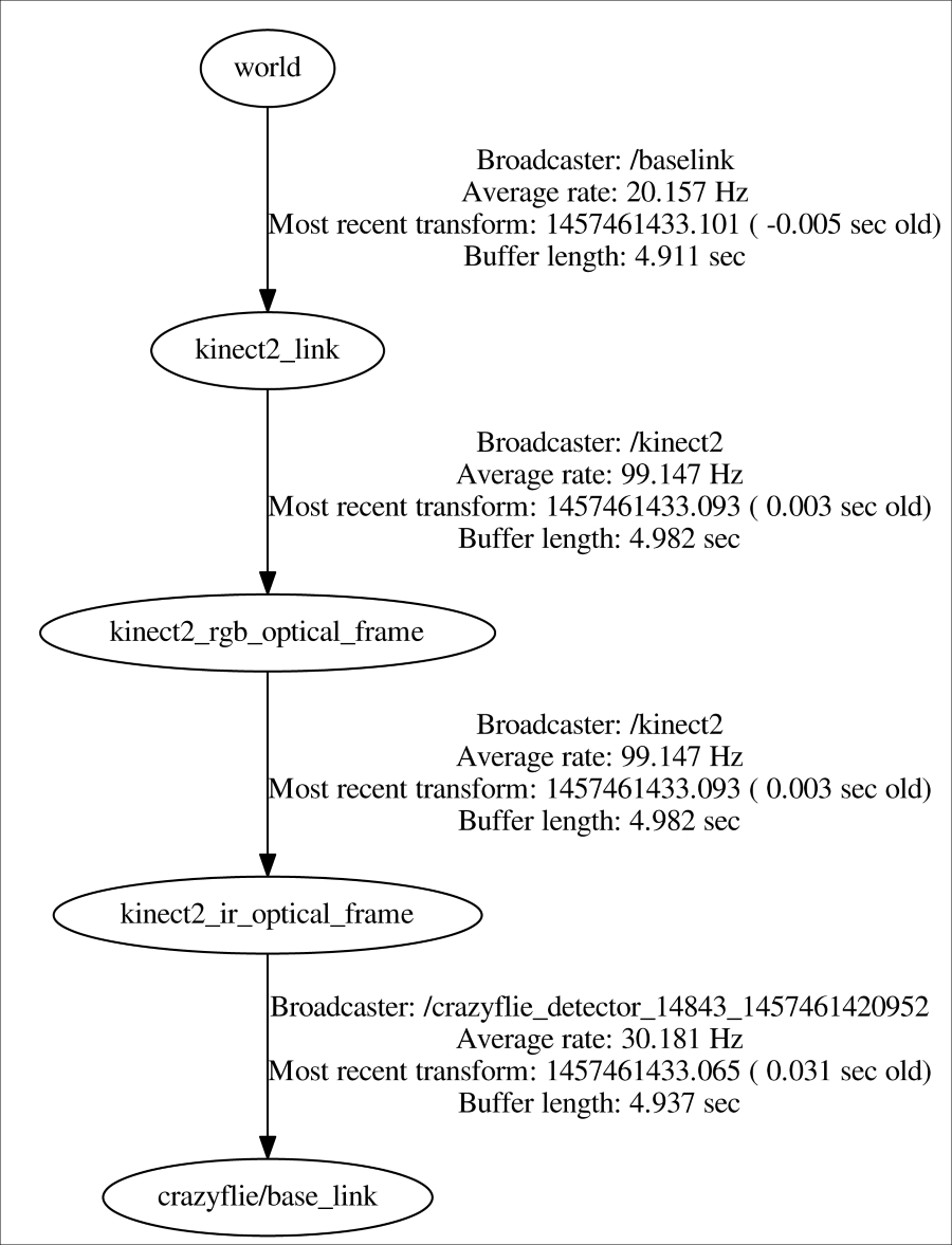
Crazyflie mission tf frames
To implement yaw control of Crazyflie, additional markers could be added to Crazyflie's structure to determine its yaw position around its vertical z axis. We have selected not to implement yaw control at this time, but plan to control Crazyflie in x, y, and z placing the quadrotor so that its x axis aligns parallel to the Kinect's -x axis. The value for yaw control will be set to 0.