Before launching Baxter Simulator in Gazebo, it is important to check the ROS environment variables. To start up Baxter Simulator, use the following commands to get to your Baxter catkin workspace and run your baxter.sh script with the sim parameter:
$ cd ~/baxter_ws
$ ./baxter.sh sim
At this point, check your ROS environment with the following command:
$ env | grep ROS
Within the output screen text, look for the following result:
ROS_MASTER_URI=http://localhost:11311
ROS_IP= <your workstation's IP address>
or
ROS_HOSTNAME=<your workstation's hostname>The ROS_HOSTNAME field need not be present.
If there are issues with Baxter's hardware, software, or network, refer to the general Baxter troubleshooting website at http://sdk.rethinkrobotics.com/wiki/Troubleshooting.
The baxter.sh script should run without errors and the ROS environment variables should be correct. The next section covers the first experience of running Baxter Simulator.
To start Baxter Simulator, go to the baxter_ws workspace and run the Baxter shell script with the sim parameter specified:
$ cd ~/baxter_ws
$ ./baxter.sh sim
The command prompt should return with the tag [baxter - http://localhost:11311] appended to the beginning of the prompt. You are now talking to the simulated Baxter!
Next, call roslaunch command to start the simulation with controllers:
$ roslaunch baxter_gazebo baxter_world.launch
The following lines are some of the results you will see on the screen while Baxter Simulator starts. Look for the last three lines to be assured that the simulation has started correctly:
NODES
  /
    base_to_world (tf2_ros/static_transform_publisher)
    baxter_emulator (baxter_sim_hardware/baxter_emulator)
    baxter_sim_io (baxter_sim_io/baxter_sim_io)
    baxter_sim_kinematics_left (baxter_sim_kinematics/kinematics)
    baxter_sim_kinematics_right (baxter_sim_kinematics/kinematics)
    gazebo (gazebo_ros/gzserver)
    gazebo_gui (gazebo_ros/gzclient)
    robot_state_publisher (robot_state_publisher/robot_state_publisher)
    urdf_spawner (gazebo_ros/spawn_model)
  /robot/
    controller_spawner (controller_manager/spawner)
    controller_spawner_stopped (controller_manager/spawner)
    left_gripper_controller_spawner_stopped (controller_manager/spawner)
    right_gripper_controller_spawner_stopped    (controller_manager/spawner)
[ INFO] [1459630925.769891432, 34.821000000]: Simulator is loaded and started successfully
[ INFO] [1459630925.773241168, 34.826000000]: Robot is disabled
[ INFO] [1459630925.773390870, 34.826000000]: Gravity compensation was turned off
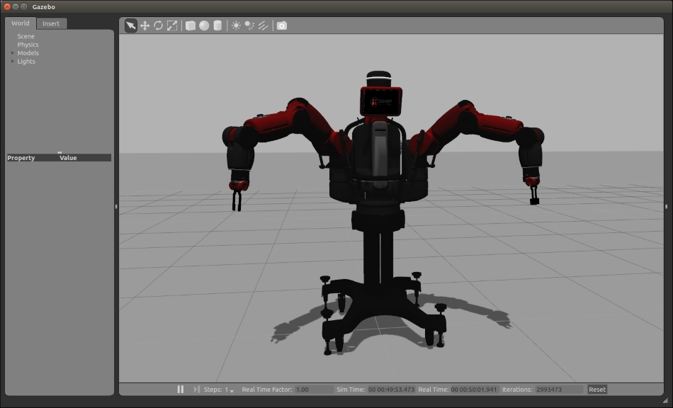
The following screenshot should appear with Baxter in a disabled state:

Baxter's initial state in Gazebo
If Gazebo and Baxter Simulator fail to appear or there are red error messages in your terminal window, refer to the Gazebo Troubleshooting page provided by Rethink Robotics at http://sdk.rethinkrobotics.com/wiki/Gazebo_Troubleshooting.
For an introduction to using Gazebo, refer to the Using Gazebo section in Chapter 2, Creating Your First Two-Wheeled ROS Robot (in Simulation). In this section, the various Gazebo display panels, menus, and toolbars are explained. Gazebo uses the same cursor/mouse control as rviz and these mouse/cursor actions are described in the rviz: Mouse control section of Chapter 2, Creating Your First Two-Wheeled ROS Robot (in Simulation).
In the previous screenshot, the left World panel shows the Models element open to reveal the two models in the environment: ground_plane and baxter. Under the baxter model, all of Baxter's links are listed and you are welcome to select the links to explore the details about each link. The screenshot also shows the smaller display window that contains Baxter's IO. Baxter's four navigators, located one on each side of the back torso (near the shoulders) and one on each arm, are also shown. The oval-shaped navigators have three push buttons, one of which is a scroll wheel. Baxter's cuff buttons are also shown in this window. There are two buttons and one touch sensor on each cuff.
The terminal window in which the roslaunch command was performed will be unable to run additional commands, so a second terminal window should be opened. In this window, go to the baxter_ws workspace and run the baxter.sh script with the sim parameter:
$ cd ~/baxter_ws
$ ./baxter.sh sim
Baxter (in simulation) is initially in a disabled state. To confirm this, use the enable_robot script from the baxter_tools package using the following command:
$ rosrun baxter_tools enable_robot.py -s
The screen should display the following output:
ready: False
enabled: False
stopped: False
error: False
estop_button: 0
estop_source: 0
To enable Baxter, use the same enable_robot script with the -e option:
$ rosrun baxter_tools enable_robot.py -e
The output is similar to the following:
[INFO] [WallTime: 1444937074.277686] [736.081000] Robot EnabledConfirm Baxter is enabled by using the following command:
$ rosrun baxter_tools enable_robot.py -s
The output should as follows:
ready: False
enabled: True
stopped: False
error: False
estop_button: 0
estop_source: 0
At this point, a cheat sheet for use with Baxter Simulator is provided for you to use with the example programs that follow. The commands for launching, enabling, and untucking are provided here for your reference:
Note
Baxter Simulator cheat sheet
To launch Baxter Simulator in Gazebo, use the following commands:
$ cd ~/baxter_ws
$ ./baxter.sh sim
$ roslaunch baxter_gazebo baxter_world.launch
For subsequent terminal windows, use the following commands:
$ cd ~/baxter_ws
$ ./baxter.sh sim
To enable the robot, use the following command:
$ rosrun baxter_tools enable_robot.py –e
To enable and set the arms in a known position, use the following command:
$ rosrun baxter_tools tuck_arms.py -u
With Baxter enabled, the next section describes some of Baxter's example scripts that use the head display screen.
Rethink Robotics has provided a collection of example scripts to demonstrate Baxter's interfaces and features. These example programs are contained in the package baxter_examples and work primarily with a real Baxter and the SDK. A portion of these example programs also work with Baxter Simulator.
The baxter_examples are Python programs that access Baxter's hardware and functionality through the baxter_interface package. The baxter_examples programs are written to demonstrate how to use the Baxter interfaces. The baxter_interface package is a repository of Python APIs to use for interacting with the Baxter Research Robot. The repository contains a set of classes that are ROS wrappers for communication to and control of Baxter's hardware and functionality. These Python classes are built on top of the ROS API layer.
This section and the following sections present SDK example programs that can be used with Baxter Simulator. To find additional information on the SDK example programs implemented in Baxter Simulator, visit the following websites:
The first example program will display an image on Baxter's (simulated) head display screen using the following command:
$ rosrun baxter_examples xdisplay_image.py --file=`rospack find baxter_examples`/share/images/baxterworking.png
Your screen should look similar to the following screenshot:

Baxter after xdisplay_image.py
The program xdisplay_image.py locates the image baxterworking.png in the specified location under the baxter_examples package. This image data is published as a sensor_msgs/Image ROS message. The display image must be a .png or .jpg file with display resolution 1024 x 600 pixels or smaller. Smaller images will appear in the top-left corner of Baxter's display screen.
A second baxter_examples program will cause Baxter Simulator to nod Baxter's head up and down then turn from side to side:
$ rosrun baxter_examples head_wobbler.py
The simulated Baxter should randomly wobble its head until Ctrl + C is pressed. The movement demonstrates both the head pan motion (side to side) and head nod motion (up and down) interfaces. This program shows the use of the baxter_interface Head class (head.py). The command_nod function is called first to trigger an up-down motion of the head. A specific angle for the nod motion cannot be commanded. The pan motion is achieved with several calls to the set_pan function with random angles provided as the parameter.
Another baxter_examples program also moves Baxter's head through a set of head positions and velocities. The Head Action Client Example demonstrates the use of the Head Action Server. This example is similar to the head wobble just performed but provides a good example of an action server and client interaction. If you wish to try the Head Action Client Example, access the instructions and explanations at http://sdk.rethinkrobotics.com/wiki/Head_Action_Client_Example.
The next section will demonstrate some example programs for Baxter's arms.
The focus of the following sections will be on Baxter's arms. The section on Bringing Baxter Simulator to life should be completed before starting these sections. Baxter Simulator should be launched in Gazebo and the robot should be enabled and arms untucked.
The following example programs use the baxter_interface Limb class (limb.py) to create instances for each arm. The function joint_names is used to return an array of all the joints in the limb.
Commands for the joint control modes are via ROS messages within the baxter_core_msgs package. To move the arm, a JointCommand message must be published on the topic robot/limb/<left/right>/joint_command. Within the JointCommand message, a mode field indicates the control mode to the Joint Controller Boards as POSITION_MODE, VELOCITY_MODE, TORQUE_MODE, or RAW_POSITON_MODE.
In the sections to follow, various methods of controlling Baxter's arm movement will be demonstrated. After several example arm programs are presented, a Python script to command Baxter's arms to a home position will be shown.
As the first step to control Baxter's arms, the tuck and untuck commands are used to bring Baxter's arms to a known configuration. The tuck operation is used to place the real Baxter in the position referred to as the shipping pose. The following figure shows Baxter in simulation in a tucked position. This pose is Baxter's most compact state and is useful for storing Baxter during inactive periods. Remember that Baxter's arm control programs cannot be run from this state. The arms must be untucked for the joints to be commanded to a specific position.
During the tuck and untuck movements, Baxter collision avoidance aspect is disabled. Collision avoidance for Baxter Simulator is modeled as part of the URDF. Each of Baxter's links is tagged with a collision block that is slightly larger than the visual element. For further details on the URDF, collision blocks, and visual element, refer to Chapter 2, Creating Your First Two-Wheeled ROS Robot (in Simulation). Typically, when the pose of the arm places the collision blocks into contact with each other, the collision model detects the contact and stops the movement to avoid collision between the actual parts.
To command Baxter to the tuck position, the following command is used:
$ rosrun baxter_tools tuck_arms.py -t
Here is the output on the screen:
[INFO] [WallTime: 1445965397.509736] [0.000000] Tucking arms
[INFO] [WallTime: 1445965397.615134] [83.930000] Moving head to neutral position
[INFO] [WallTime: 1445965397.615655] [83.931000] Tucking: One or more arms not Tucked.
[INFO] [WallTime: 1445965397.615829] [83.931000] Moving to neutral start position with collision on.
[INFO] [WallTime: 1445965399.012163] [85.320000] Tucking: Tucking with collision avoidance off.
[INFO] [WallTime: 1445965399.612480] [85.920000] Finished tuck
This screenshot shows the simulated Baxter in the tucked position:

Baxter tucked
To command Baxter to the untuck position, use the following command:
$ rosrun baxter_tools tuck_arms.py –u
The output should be as follows:
[INFO] [WallTime: 1444940090.850322] [0.000000] Untucking arms
[INFO] [WallTime: 1444940090.955454] [3742.494000] Moving head to neutral position
[INFO] [WallTime: 1444940090.955729] [3742.494000] Untucking: Arms already Untucked; Moving to neutral position.
[INFO] [WallTime: 1444940092.864302] [3744.397000] Finished tuck
The following screenshot shows the simulated Baxter in the untucked position:

Baxter untucked
To explore Baxter's tuck and untuck operations further, refer to the Rethink wiki Tuck Arms Tool information at http://sdk.rethinkrobotics.com/wiki/Tuck_Arms_Tool.
The next example program provides a demonstration of controlling Baxter's arms using joint velocity control. The subject matter of joint control modes for Baxter's arms has been described previously in the Baxter's arms section. In simulation, the joint velocity wobble can be observed by typing the command:
$ rosrun baxter_examples joint_velocity_wobbler.py
The output should be as follows:
Initializing node...
Getting robot state...
Enabling robot...
[INFO] [WallTime: 1445967379.527851] [2059.870000] Robot Enabled
Moving to neutral pose...
Wobbling. Press Ctrl-C to stop...
^C
Exiting example...
Moving to neutral pose...
The program will begin by moving Baxter's arms to a preset neutral starting position. Next, random velocity commands are sent to each arm to create a sinusoidal motion across both limbs. The following screenshot shows Baxter's neutral starting position:
Baxter's neutral position
To explore Baxter's arms' joint_velocity_wobbler operation in more detail, refer to the Rethink wiki Wobbler Example information at http://sdk.rethinkrobotics.com/wiki/Wobbler_Example.
Baxter's arms can also be controlled with keyboard keystrokes. The keystrokes are used to control the positions of the joints, with each keyboard key mapped to either increase or decrease the angle of one of Baxter's 14 arm joints. Keys on the right side of the keyboard are mapped to Baxter's left arm and keys on the left side of the keyboard are mapped to Baxter's right arm.
This example demonstrates another of Baxter's arm control modes: joint position control.
To start the keyboard joint position control example, use the following command:
$ rosrun baxter_examples joint_position_keyboard.py
This should be the output on the screen:
Initializing node...
Getting robot state...
Enabling robot...
[INFO] [WallTime: 1444939449.128589] [3103.020000] Robot Enabled
Controlling joints. Press ? for help, Esc to quit.
key bindings:
  Esc: Quit
  ?: Help
|
/: left: gripper calibrate ,: left: gripper close m: left: gripper open y: left_e0 decrease o: left_e0 increase u: left_e1 decrease i: left_e1 increase 6: left_s0 decrease 9: left_s0 increase 7: left_s1 decrease 8: left_s1 increase h: left_w0 decrease l: left_w0 increase j: left_w1 decrease k: left_w1 increase n: left_w2 decrease .: left_w2 increase |
b: right: gripper calibrate c: right: gripper close x: right: gripper open q: right_e0 decrease r: right_e0 increase w: right_e1 decrease e: right_e1 increase 1: right_s0 decrease 4: right_s0 increase 2: right_s1 decrease 3: right_s1 increase a: right_w0 decrease f: right_w0 increase s: right_w1 decrease d: right_w1 increase z: right_w2 decrease v: right_w2 increase |
This example program uses a joystick to control Baxter's arms. The joint_position_joystick program uses the ROS drivers from the joy package to interface with a generic Linux joystick. Joysticks with a USB interface are supported by the joy package. The joy package creates a joy_node to generate a joy_msg containing the various button push and joystick move events.
The first step is to check for the joystick driver package joy using the following command:
$ rospack find joy
If the ROS package is on the computer, the screen should display this:
/opt/ros/indigo/share/joyIf it is not, then an error message is displayed:
[rospack] Error: stack/package joy not foundIf the joy package is not present, install it with the following command:
$ sudo apt-get install ros-indigo-joystick-drivers
For a PS3 joystick controller, you will need the ps3joy package. Instructions can be found at http://wiki.ros.org/ps3joy/Tutorials/PairingJoystickAndBluetoothDongle.
Next, type the command to start the joint_position_joystick program using one of the joystick types (xbox, logitech, or ps3):
$ roslaunch baxter_examples joint_position_joystick.launch joystick:=<joystick_type>
We used the Xbox controller joystick in our example; the output is as follows:
...
NODES
  /
    joy_node (joy/joy_node)
    rsdk_joint_position_joystick (baxter_examples/joint_position_joystick.py)
...
[INFO] [WallTime: 1444940605.062164] [4255.152000] Robot Enabled
Press Ctrl-C to quit.
rightTrigger: left gripper close
rightTrigger: left gripper open
leftTrigger: right gripper close
leftTrigger: right gripper open
leftStickHorz: right inc right_s0
leftStickHorz: right dec right_s0
rightStickHorz: left inc left_s0
rightStickHorz: left dec left_s0
leftStickVert: right inc right_s1
leftStickVert: right dec right_s1
rightStickVert: left inc left_s1
rightStickVert: left dec left_s1
rightBumper: left: cycle joint
leftBumper: right: cycle joint
btnRight: left calibrate
btnLeft: right calibrate
function1: help
function2: help
Press Ctrl-C to stop.
The preceding output shows the Xbox joystick buttons and knobs to move Baxter's joints. The joystick controls two joints at a time on each of Baxter's two arms by using the Left Stick and the Right Stick (see following diagram). The up-down (vertical) control of the stick controls increasing and decreasing one of the joint angles. The side-to-side (horizontal) control increases and decreases another joint angle. The Left Bumper and Right Bumper cycle the joystick control through all of Baxter's arm joints in the order: S0-S1-E0-E1-W0-W1-W2. For example, initially the Left Stick control will be in command of the (right arm) S0 joint using horizontal direction and the S1 joint using vertical direction. When the Left Bumper is pressed, the Left Stick horizontal control will command the S1 joint and the vertical control will command the E0 joint. Cycling the joints continues in a continuous loop where the S0 joint will be selected next after the W2 joint.
The following diagram and table describe the mapping of the Xbox joystick controls:

Xbox joystick controls
|
Buttons |
Action for RIGHT Arm |
Buttons |
Action for LEFT Arm |
|---|---|---|---|
|
Back |
Help |
Ctrl+C or Ctrl+Z |
Quit |
|
Left Button (X) |
gripper calibrate |
Right Button (B) |
gripper calibrate |
|
Top Button (Y) |
none |
Bottom Button (A) |
none |
|
Left Trigger [PRESS] |
gripper close |
Right Trigger[PRESS] |
gripper close |
|
Left Trigger [RELEASE] |
gripper open |
Right Trigger[RELEASE] |
gripper open |
|
Left Bumper |
cycle joints |
Right Bumper |
cycle joints |
|
Stick Axes |
Action |
|---|---|
|
Left Stick Horizontal |
right: increase/decrease <current joint 1> (S0) |
|
Left Stick Vertical |
right: increase/decrease <current joint 2> (S1) |
|
Right Stick Horizontal |
left: increase/decrease <current joint 1> (S0) |
|
Right Stick Vertical |
left: increase/decrease <current joint 2> (S1) |
In this section, we will create a simple Python script to command Baxter's arms to a specific pose. The following script commands Baxter's arms to a home position similar to the tuck position. Comments have been placed throughout the code to provide information on the process. Further explanation of the Python code operation is given following the script:
#!/usr/bin/env python

"""
Script to return Baxter's arms to a "home" position
"""

# rospy - ROS Python API
import rospy

# baxter_interface - Baxter Python API
import baxter_interface

# initialize our ROS node, registering it with the Master
rospy.init_node('Home_Arms')

# create instances of baxter_interface's Limb class
limb_right = baxter_interface.Limb('right')
limb_left = baxter_interface.Limb('left')

# store the home position of the arms
home_right = {'right_s0': 0.08, 'right_s1': -1.00, 'right_w0': -0.67, 'right_w1': 1.03, 'right_w2': 0.50, 'right_e0': 1.18, 'right_e1': 1.94}
home_left = {'left_s0': -0.08, 'left_s1': -1.00, 'left_w0': 0.67, 'left_w1': 1.03, 'left_w2': -0.50, 'left_e0': -1.18, 'left_e1': 1.94}

# move both arms to home position
limb_right.move_to_joint_positions(home_right)
limb_left.move_to_joint_positions(home_left)

quit()
This code can be placed in a file home_arms.py and executed after it is made executable using the Ubuntu chmod +x command with this terminal command:
$ python home_arms.py
In this script, the ROS-Python interface package rospy is used to create ROS components from Python code. The rospy client API provides software routines for initializing the ROS node, Home_Arms, to invoke the process. The baxter_interface package provides the API for interacting with Baxter. In the script, we instantiate instances of the limb class for both the right and left arms. A Python dictionary is used to assign joint angles to specific joints for both the right arm and left arm. These joint angle dictionaries are passed to the move_to_joint_positions method to command the respective arm to the provided position. The move_to_joint_positions method is also a part of the baxter_interface package.
Another capability provided by the baxter_examples programs is the ability to record and playback arm positions. A recorder program captures the time and joint positions to an external file. The filename armRoutine is used in the following command lines, but you may substitute your own filename instead. After the command for the recorder program is executed, the operator should move Baxter's arms by hand or by using the keyboard, joystick, ROS commands, or a script. When the operator wishes to end the recording, Ctrl + C or Ctrl + Z must be pressed to stop the recording. The playback program can be executed with the external file passed as a parameter. The playback program will run through the arm positions in the file once and then exit. The following instructions show the commands and the order of operation:
$ rosrun baxter_examples joint_recorder.py -f armRoutine
The output should be as follows:
Initializing node...
Getting robot state...
Enabling robot...
[INFO] [WallTime: 1444942596.926847] [6239.995000] Robot Enabled
Recording. Press Ctrl-C to stop.
At this time, you should use the joystick, keyboard, Python script, and/or commands to move Baxter's arms. Press Ctrl + C when you are finished moving Baxter's arms. Next, execute the following command to playback the file:
$ rosrun baxter_examples joint_position_file_playback.py -f armRoutine
The output on the screen should be similar to the following:
Initializing node...
Getting robot state...
Enabling robot...
[INFO] [WallTime: 1444943103.913642] [6745.321000] Robot Enabled
Playing back: armRoutine
Moving to start position...
 Record 10462 of 10462, loop 1 of 1


Exiting example...
If the file armRoutine is brought up in an editor, you should see that it contains data similar to the following:
time,left_s0,left_s1,left_e0,left_e1,left_w0,left_w1,left_w2,left_gripper,right_s0,right_s1,right_e0,right_e1,right_w0,right_w1,right_w2,right_gripper

0.221000,-0.0799704928309,-1.0000362209,-0.745950772448,-0.0499208630966,-1.6948350728,1.03001017593,-0.500000660376,0.0,-1.04466483018,-0.129655442605,1.5342459042,1.94952695585,-0.909650985497,1.03000093981,0.825985250377,0.0
...
As shown, the first line contains the labels for the data on each of the subsequent rows. As the first label indicates, the first field contains the timestamp. The subsequent fields hold the joint positions for each of the left and right arm joints and grippers.
The velocity controllers and the position controllers for Baxter's arm joints can be tweaked using an rqt dashboard GUI. Baxter Simulator should be running velocity or position joint control mode before using one of the following command to launch rqt. For position control mode, use the following command:
$ roslaunch baxter_sim_hardware baxter_sdk_position_rqt.launch
For velocity control mode, you can use the following command:
$ roslaunch baxter_sim_hardware baxter_sdk_velocity_rqt.launch
The following figure shows the rqt Dynamic Configure plugin position controller GUI where the PID values can be modified for Baxter Simulator:
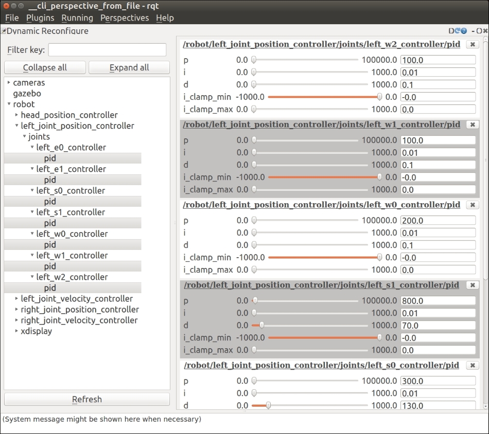
rqt GUI control for Baxter's positon controllers