In the next few sections, our rrbot URDF will be created and incrementally built to incorporate the advantages of each of the Xacro features we discussed for our robot.
For the first iteration of our rrbot robot arm, we will build a URDF file that defines three links with the <visual>, <collision>, and <inertial> tags, and two joints with the <parent>, <child>, <origin>, and <axis> tags. This is a very similar format to the dd_robot URDF file that you are familiar with from Chapter 2, Creating Your First Two-Wheeled ROS Robot (in Simulation). The differences for the Xacro format are listed here and explained in more detail after the code is presented:
- Addition of the XML namespace declaration on the second line
- Use of the Xacro
<property>tag to define constant values - Addition of property names instead of values within the
<box>and<origin>tags - Simple math (along with property names) to calculate link
<origin>z values - Joints for this arm are revolute and have the additional tags of
<dynamics>and<limit>
The rrbot.xacro file can be downloaded from the Packt website, or you can enter the following code into your favorite editor:
<?xml version="1.0">
<!-- Revolute-Revolute Manipulator -->
<robot xmlns:xacro="http://www.ros.org/wiki/xacro" name="rrbot">
  <!-- Constants for robot dimensions -->
  <xacro:property name="width" value="0.1" />
  <xacro:property name="height1" value="2" />
  <xacro:property name="height2" value="1" />
  <xacro:property name="height3" value="1" />
  <xacro:property name="axle_offset" value="0.05" />
  <xacro:property name="damp" value="0.7" />

  <!-- Base Link -->
  <link name="base_link">
    <visual>
      <origin xyz="0 0 ${height1/2}" rpy="0 0 0" />
      <geometry>
        <box size="${width} ${width} ${height1}" />
      </geometry>
    </visual>
    <collision>
      <origin xyz="0 0 ${height1/2}" rpy="0 0 0" />
      <geometry>
        <box size="${width} ${width} ${height1}" />
      </geometry>
    </collision>
    <inertial>
      <origin xyz="0 0 ${height1/2}" rpy="0 0 0" />
      <mass value="1" />
      <inertia ixx="1.0" ixy="0.0" ixz="0.0" iyy="1.0" iyz="0.0" izz="1.0" />
    </inertial>
  </link>

  <!-- Joint between Base Link and Middle Link -->
  <joint name="joint_base_mid" type="revolute">
    <parent link="base_link" />
    <child link="mid_link" />
    <origin xyz="0 ${width} ${height1 - axle_offset}" rpy="0 0  0" />
    <axis xyz="0 1 0" />
    <dynamics damping="${damp}" />
    <limit effort="100.0" velocity="0.5" lower="-3.14" upper="3.14" />
  </joint>

  <!-- Middle Link -->
  <link name="mid_link">
    <visual>
      <origin xyz="0 0 ${height2/2 - axle_offset}" rpy="0 0 0" />
      <geometry>
        <box size="${width} ${width} ${height2}" />
      </geometry>
    </visual>
    <collision>
      <origin xyz="0 0 ${height2/2 - axle_offset}" rpy="0 0 0" />
      <geometry>
        <box size="${width} ${width} ${height2}" />
      </geometry>
    </collision>
    <inertial>
      <origin xyz="0 0 ${height2/2 - axle_offset}" rpy="0 0 0" />
      <mass value="1" />
      <inertia ixx="1.0" ixy="0.0" ixz="0.0" iyy="1.0" iyz="0.0" izz="1.0" />
    </inertial>
  </link>

  <!-- Joint between Middle Link and Top Link -->
  <joint name="joint_mid_top" type="revolute">
    <parent link="mid_link" />
    <child link="top_link" />
    <origin xyz="0 ${width} ${height2 - axle_offset*2}" rpy="0 0  0" />
    <axis xyz="0 1 0" />
    <dynamics damping="${damp}" />
    <limit effort="100.0" velocity="0.5" lower="-3.14" upper="3.14" />
  </joint>

  <!-- Top Link -->
  <link name="top_link">
    <visual>
      <origin xyz="0 0 ${height3/2 - axle_offset}" rpy="0 0 0" />
      <geometry>
        <box size="${width} ${width} ${height3}" />
      </geometry>
    </visual>
    <collision>
      <origin xyz="0 0 ${height3/2 - axle_offset}" rpy="0 0 0" />
      <geometry>
        <box size="${width} ${width} ${height3}" />
      </geometry>
    </collision>
    <inertial>
      <origin xyz="0 0 ${height3/2 - axle_offset}" rpy="0 0 0" />
      <mass value="1" />
      <inertia ixx="1.0" ixy="0.0" ixz="0.0" iyy="1.0" iyz="0.0" izz="1.0" />
    </inertial>
  </link>
</robot>
This file and all .xacro files should be saved in the /urdf directory of your ros_robotics package.
This XML code defines a robot arm, labeled rrbot, which has three links that are 0.1 meters deep and wide. The base_link is 2 meters tall, and the mid_link and top_link are both 1 meter tall. The origin of the base_link is at (0, 0, 1) in order for the arm to be above the ground plane in rviz. The reference frame of the box is 1 meter in the z direction above the reference frame of the link. This base_link is identified as the URDF root link and is the beginning of the kinematic chain for the arm. The collision elements of each match their visual elements. Each inertial element indicates that each link weighs 1 kilogram and has the same basic inertia matrix values. (We will utilize this duplication of the inertial element when we improve the code for rrbot later in this chapter.)
In rrbot.xacro, the <property> elements are used for constants for the dimensions of the links, the offset for the axis of rotation, and for the damping coefficient. These values are declared at the beginning of the XML code, making it easy to change the size of the links, the limits of the joints' rotation, or the damping characteristics of the arm.
Two new tags have been added to the <dynamics damping> and <limit> joint elements. The dynamics damping coefficient is set to 0.7 Nms/rad. This damping is the amount of opposing force to any joint velocity, used to slow down the moving arms to a rest position. Using the <property> element, this damping value can be changed in one location. You are encouraged to change the value when you run the rrbot URDF/SDF with Gazebo and see the changes made to the pendulum swinging motion. The <limit> tag is required for revolute joints. The limit effort is set to 1000.0 N-m for the maximum joint effort that can be commanded. The joint velocity is limited to a magnitude of 0.5 rad/s, with a damping effort applied when the joint is commanded beyond this limit. The upper and lower limits of the joint are set to pi radians and -pi radians, respectively.
Modifications made to the launch file in rviz are necessary, but you will notice similarities to the ddrobot_rviz.launch file in Chapter 2, Creating Your First Two-Wheeled Robot (in Simulation). Either download the rrbot_rviz.launch file from the ros_robotics/launch directory on this book's website, or create the rrbot_rviz.launch file from the following code:
<launch>
  <!-- set parameter on Parameter Server -->
  <arg name="model" />
  <param name="robot_description"
    command="$(find xacro)/xacro.py
            '$(find ros_robotics)/urdf/$(arg model)'" />

  <!-- send joint values from gui -->
  <node name="joint_state_publisher" pkg="joint_state_publisher"
        type="joint_state_publisher">
    <param name="use_gui" value="TRUE"/>
  </node>

  <!-- use joint positions to update tf -->
  <node name="robot_state_publisher" pkg="robot_state_publisher"
        type="state_publisher"/>

  <!-- visualize robot model in 3D -->
  <node name="rviz" pkg="rviz" type="rviz"
        args="-d $(find ros_robotics)/urdf.rviz" required="true" />

</launch>
The main difference in this rviz launch file is executing xacro.py with the argument passed as the model parameter. This process will generate the robot_description parameter to be loaded on the Parameter Server. Make sure that you place this rrbot_rviz.launch file in the /launch directory of your ros_robotics directory.
Note
If you have added the ROS_MASTER_URI and ROS_HOSTNAME or ROS_IP environment variables to your .bashrc file, you will need to comment out these lines with a # as the first character of the line. Add the following two commands to your .bashrc file to be able to execute the ROS commands used in this chapter:
export ROS_MASTER_URI=http://localhost:11311//
export ROS_HOSTNAME=localhost
Next, run your rviz roslaunch command:
$ roslaunch ros_robotics rrbot_rviz.launch model:=rrbot.xacro
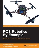
The rviz screen will look similar to the following screenshot:
rrbot.xacro in rviz
In the preceding screenshot, notice the pop-up window with two joint control sliders for joint_base_mid and joint_mid_top. The center (0.00) position for both the joints puts the arm in a vertical position. You are encouraged to play with the sliders and the Randomize and Center buttons to understand the controls for the arm joints.
In the following increment of the rrbot Xacro file, we will use an Xacro <include> tag to specify colors for each link of the robot arm. The materials.xacro file must be in the ros_robotics/urdf directory. To create the materials.xacro file, use the following code:
<?xml version="1.0"?>
<robot>

  <material name="black">
    <color rgba="0.0 0.0 0.0 1.0"/>
  </material>

  <material name="blue">
    <color rgba="0.0 0.0 0.8 1.0"/>
  </material>

  <material name="green">
    <color rgba="0.0 1.0 0.0 1.0"/>
  </material>

  <material name="grey">
    <color rgba="0.2 0.2 0.2 1.0"/>
  </material>

  <material name="orange">
    <color rgba="${255/255} ${108/255} ${10/255} 1.0"/>
  </material>

  <material name="brown">
    <color rgba="${222/255} ${207/255} ${195/255} 1.0"/>
  </material>

  <material name="red">
    <color rgba="0.8 0.0 0.0 1.0"/>
  </material>

  <material name="white">
    <color rgba="1.0 1.0 1.0 1.0"/>
  </material>

</robot>
Color values can be modified to your preferences for colors and textures. Within each <visual> element of the arm link, the following code should be added with an appropriate color:
<material name="any color defined in materials.xacro"/>
An Xacro <macro> block is also added to the rrbot Xacro file to replace the duplicate inertial elements in each link. The macro for <inertial> is as follows:
  <xacro:macro name="default_inertial" params="z_value i_value mass">
    <inertial>
      <origin xyz="0 0 ${z_value}" rpy="0 0 0"/>
      <mass value="${mass}" />
      <inertia ixx="${i_value}" ixy="0.0" ixz="0.0"
        iyy="${i_value}" iyz="0.0"
        izz="${i_value}" />
      </inertial>
  </xacro:macro>
Within each <link> of the arm, the entire <inertial> block is replaced with the following code:
<xacro:default_inertial z_value="${computation for <origin> in z-axis}" i_value="1.0" mass="1"/>Study the following code to understand the computation for <origin> in z axis. This code is in the rrbot2.xacro file available for download on the book's website, or can be entered from the following lines: (lines from the previous code have been highlighted):
<?xml version="1.0"?>
<!-- Revolute-Revolute Manipulator -->
…

  <!-- Import Rviz colors -->
  <xacro:include
           filename="$(find ros_robotics)/urdf/materials.xacro" />

  <!-- Default Inertial -->
  <xacro:macro name="default_inertial" params="z_value i_value mass">
    <inertial>
      <origin xyz="0 0 ${z_value}" rpy="0 0 0"/>
      <mass value="${mass}" />
      <inertia ixx="${i_value}" ixy="0.0" ixz="0.0"
               iyy="${i_value}" iyz="0.0"
               izz="${i_value}" />
      </inertial>
  </xacro:macro>

  <!-- Base Link -->
    …
    </collision>

    <xacro:default_inertial z_value="${height1/2}"
                            i_value="1.0" mass="1"/>
  </link>
  …
  <!-- Middle Link -->
    …
    </collision>

    <xacro:default_inertial z_value="${height2/2 - axle_offset}"
    i_value="1.0" mass="1"/>
  </link>
  …
  <!-- Top Link -->
    …
    </collision>

    <xacro:default_inertial z_value="${height3/2 - axle_offset}"
      i_value="1.0" mass="1"/>
  </link>

</robot>
Next, run the rviz roslaunch command:
$ roslaunch ros_robotics rrbot_rviz.launch model:=rrbot2.xacro
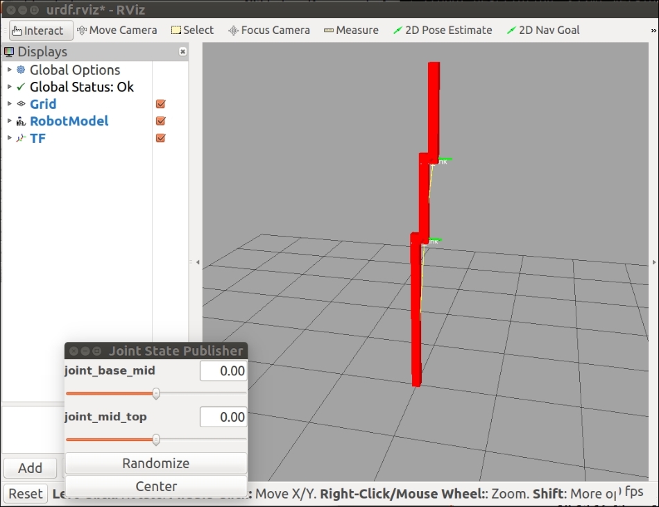
The rviz screen will look similar to the following screenshot:
rrbot2.xacro in rviz
Although the book may show the screenshot in shades of gray, the base_link of the arm is now red, the mid_link is green, and the top_link is blue. On your screen, you will see the colors specified in your rrbot2.xacro file. The arm is shown in a random pose.
A mesh is a collection of polygon surfaces that provides a more realistic shape for an object in 3D. Although adding a mesh to the URDF is not specific to Xacro, we include the exercise here to give you the experience of using meshes and to append a more realistic gripper for our robot arm.
For the next upgrade to our robot arm, we will add a composite mesh image of a gripper to the top_link of the arm. To make our code design modular, we will create the gripper code in a separate file and use an Xacro <include> statement in the main rrbot3.xacro file:
<xacro:include filename="$(find ros_robotics)/urdf/gripper.xacro" />
Using this <include> statement, the gripper.xacro file must be in the ros_robotics/urdf directory.
The gripper is defined as four links with the <visual>, <collision>, and <inertial> tags, and four joints with the <parent>, <child>, <origin>, and <axis> tags. The four links are identified as the left_gripper, left_tip, right_gripper, and right_tip. The links utilize mesh files from the PR2 robot for their <visual> and <geometry> definitions. The PR2 robot is another famous Willow Garage robot, now mainly used for academic research. The PR2_description Xacro files are part of the ros-indigo-desktop-full installation described in the Installing and launching ROS section in Chapter 1, Getting Started with ROS. The files used for the gripper are found in the /opt/ros/indigo/share/pr2_description/meshes/gripper_v0 directory. The l_finger.dae and l_finger_tip.dae files should be copied to a /meshes directory under your ros_robotics package directory, or they can be downloaded from the example code on the book's website.
Code to add the mesh file to the left_gripper link:
  <link name="left_gripper">
    <visual>
      <origin rpy="0 0 0" xyz="0 0 0"/>
      <geometry>
        <mesh filename="package://ros_robotics/meshes/l_finger.dae"/>
      </geometry>
    </visual>
The other links follow the same format with the left_tip and right_tip links, utilizing the l_finger_tip.dae file. The .dae file is a Digital Asset Exchange file in the COLLADA format, representing a 3D image. These images can be created in Photoshop, SketchUp, AutoCAD, Blender, and other graphics software.
You can use the same geometry or meshes for both the <collision> and <visual> elements, although for performance improvements, we strongly suggest that you have simplified models/meshes for your collision geometry. A good open source tool used to simplify meshes is Blender. There are many closed source tools, such as Maya and 3DS Max, which can also simplify meshes. In the case of our robot arm, we specify a simple 0.1 meter cube to be the <collision> and <geometry> for each of these links.
Two types of joints are used for our gripper. The left_gripper and right_gripper links are connected to the top_link of our robot arm using a revolute joint to restrict the range of movement of the joint. A <limit> tag is required for a revolute joint to define the <effort>, <velocity>, and <lower> and <upper> limits of the range. The effort limit is set to 30 Nm, the velocity limit is 0.5 rad/s, and the range is from -0.548 to 0.0 radians for the left_gripper_joint and 0.0 to 0.548 radians for the right_gripper_joint.
A fixed joint is specified between the left_gripper and the left_tip and also between the right_gripper and the right_tip. There is no movement between these links.
This following code is provided for gripper.xacro, or it can be downloaded from the Packt website for this book:
<?xml version="1.0"?>
<robot xmlns:xacro="http://www.ros.org/wiki/xacro">

  <!-- Gripper -->
  <joint name="left_gripper_joint" type="revolute">
    <parent link="top_link"/>
    <child link="left_gripper"/>
    <origin xyz="0 0 ${height2 - axle_offset}" rpy="0 -1.57 0"/>
    <axis xyz="0 0 1"/>
    <limit effort="30.0" lower="-0.548" upper="0.0" velocity="0.1"/>
  </joint>

  <link name="left_gripper">
    <visual>
      <origin rpy="0 0 0" xyz="0 0 0"/>
      <geometry>
        <mesh filename="package://ros_robotics/meshes/l_finger.dae"/>
      </geometry>
    </visual>

    <collision>
      <geometry>
        <box size="0.1 0.1 0.1"/>
      </geometry>
    </collision>
    <xacro:default_inertial z_value="0" i_value="0.000001" mass="1"/>
  </link>

  <joint name="left_tip_joint" type="fixed">
    <parent link="left_gripper"/>
    <child link="left_tip"/>
  </joint>

  <link name="left_tip">
    <visual>
      <origin rpy="0 0 0" xyz="0.09137 0.00495 0"/>
      <geometry>
        <mesh
          filename="package://ros_robotics/meshes/l_finger_tip.dae"/>
      </geometry>
    </visual>

    <collision>
      <geometry>
        <box size="0.1 0.1 0.1"/>
      </geometry>
    </collision>
    <xacro:default_inertial z_value="0" i_value="1e-6" mass="1e-5"/>
  </link>

  <joint name="right_gripper_joint" type="revolute">
    <parent link="top_link"/>
    <child link="right_gripper"/>
    <origin xyz="0 0 ${height2 - axle_offset}" rpy="0 -1.57 0"/>
    <axis xyz="0 0 -1"/>
    <limit effort="30.0" lower="0.0" upper="0.548" velocity="0.5"/>
  </joint>

  <link name="right_gripper">
    <visual>
      <origin rpy="3.1415 0 0" xyz="0 0 0"/>
      <geometry>
        <mesh filename="package://ros_robotics/meshes/l_finger.dae"/>
      </geometry>
    </visual>

    <collision>
      <geometry>
        <box size="0.1 .1 .1"/>
      </geometry>
    </collision>
    <xacro:default_inertial z_value="0" i_value="1e-6" mass="1"/>
  </link>

  <joint name="right_tip_joint" type="fixed">
    <parent link="right_gripper"/>
    <child link="right_tip"/>
  </joint>

  <link name="right_tip">
    <visual>
      <origin rpy="-3.1415 0 0" xyz="0.09137 0.00495 0"/>
      <geometry>
        <mesh
          filename="package://ros_robotics/meshes/l_finger_tip.dae"/>
      </geometry>
    </visual>

    <collision>
      <geometry>
        <box size="0.1 .1 .1"/>
      </geometry>
    </collision>
    <xacro:default_inertial z_value="0" i_value="1e-6" mass="1e-5"/>
  </link>
</robot>
Next, run the rviz roslaunch command:
$ roslaunch ros_robotics rrbot_rviz.launch model:=rrbot3.xacro
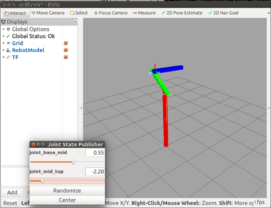
A close-up view of the gripper should look similar to the following screenshot:
rrbot gripper in rviz
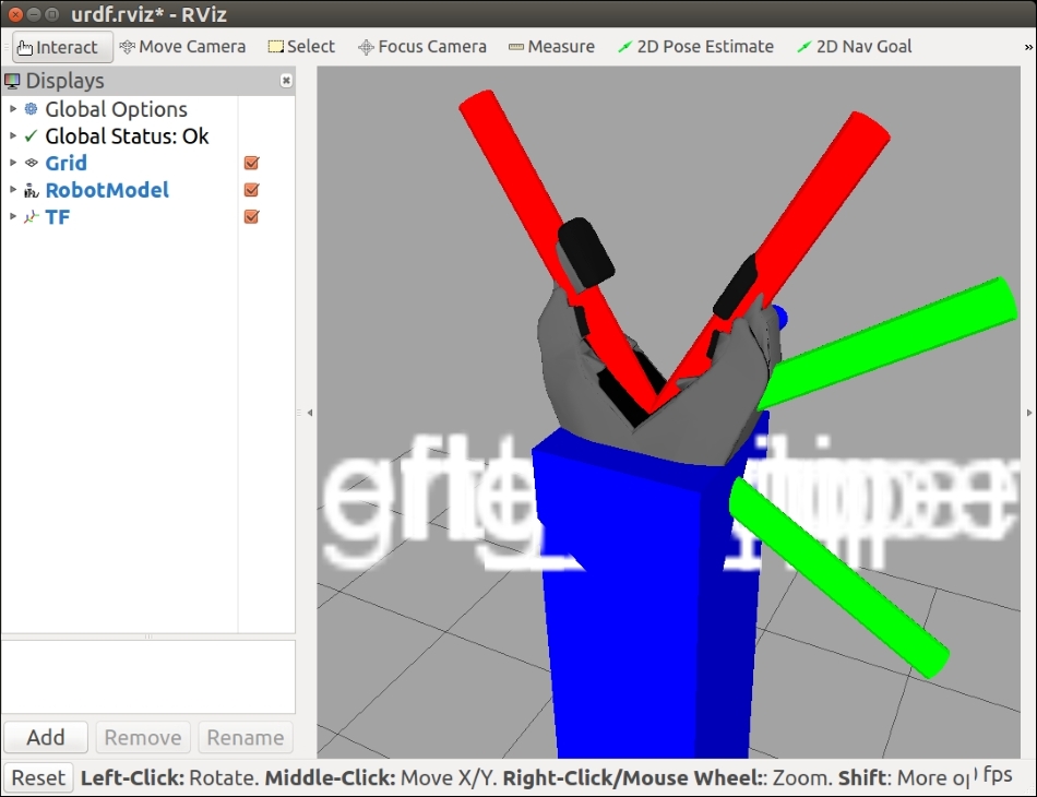
The controls for the arm and gripper are accessible via the four joint control sliders, as shown in the following screenshot. Controls for left_gripper_joint and right_gripper_joint have been added to the arm joints. The robot arm is shown in a random pose:
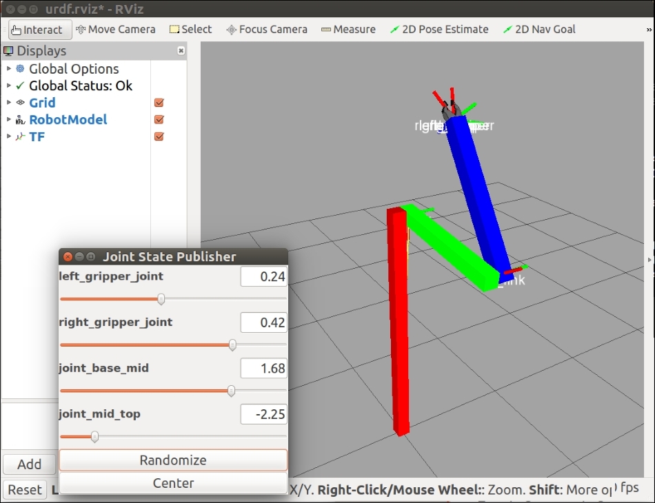
rrbot3.xacro in rviz
With our robot arm built using Xacro, we are ready to add modifications to the Xacro file so that it can be recognized as an SDF by Gazebo. Then, we will add transmission and control plugins to enable our robot arm to be controlled by ROS commands from the command line or rqt.