The Modifications to the robot URDF section in Chapter 2, Creating Your First Two-Wheeled Robot (in Simulation) describes changes that need to be made to the URDF model so that Gazebo recognizes it as an SDF. The next section identifies the changes needed for our robot arm, rrbot.
Specific elements unique to the Gazebo simulation environment are grouped in the following areas:
- The
<material>tags are used to specify the Gazebo color or texture for each link - The
<mu1>and<mu2>tags are used to define friction coefficients for the contact surfaces for four of the robot's links - Plugin to control the revolute joints of
rrbot(included here but described in the Adding a Gazebo ROS control plugin section)
These specific Gazebo XML elements needed for simulation are split into a separate file, labeled rrbot.gazebo, and an Xacro <include> statement is used in the main rrbot4.xacro file:
<xacro:include filename="$(find ros_robotics)/urdf/rrbot.gazebo" />
Using this <include> statement, the rrbot.gazebo file must be located in the ros_robotics/urdf directory.
To create the rrbot.gazebo file, use the following code:
<?xml version="1.0"?>
<robot>

  <!-- Base Link -->
  <gazebo reference="base_link">
    <material>Gazebo/Red</material>
  </gazebo>

  <!-- Middle Link -->
  <gazebo reference="mid_link">
    <mu1>0.2</mu1>
    <mu2>0.2</mu2>
    <material>Gazebo/Green</material>
  </gazebo>

  <!-- Top Link -->
  <gazebo reference="top_link">
    <mu1>0.2</mu1>
    <mu2>0.2</mu2>
    <material>Gazebo/Blue</material>
  </gazebo>

  <!-- Gripper Elements -->
  <gazebo reference="left_gripper">
    <mu1>0.2</mu1>
    <mu2>0.2</mu2>
  </gazebo>

  <gazebo reference="right_gripper">
    <mu1>0.2</mu1>
    <mu2>0.2</mu2>
  </gazebo>

  <gazebo reference="left_tip" />
  <gazebo reference="right_tip" />

  <!-- ros_control plugin -->
  <gazebo>
    <plugin name="gazebo_ros_control"
            filename="libgazebo_ros_control.so">
      <robotNamespace>/rrbot</robotNamespace>
      <robotSimType>
        gazebo_ros_control/DefaultRobotHWSim
      </robotSimType>
    </plugin>
  </gazebo>

</robot>Since Gazebo simulates the physics of the real world, a robot arm, as we have defined it, will not stand up for long as the force of gravity will cause it to topple. Therefore, we need to attach our robot arm model to Gazebo's world frame. In the rrbot4.xacro version of our code, a world link has been added and a joint fixing our robot's base_link to the world link:
  <link name="world"/>

  <joint name="fixed" type="fixed">
    <parent link="world"/>
    <child link="base_link"/>
  </joint>
With the base_link of the arm fixed to the world link, the mid_link and top_link will still succumb to the force of gravity. Although the robot arm appears to be standing straight up when the arm is launched in Gazebo, you will see that these top two links of the arm fall. The arm will swing and slow due to the <dynamics> element defined for the joint, until it comes to a complete stop. We encourage you to play with the <damping> value in order to understand its property in relation to the Gazebo simulation.
Before we continue to add control elements to our URDF, we need to launch the rrbot4.xacro file in Gazebo. This launch file is similar to the ddrobot_gazebo.launch file in Chapter 2, Creating Your First Two-Wheeled Robot (in Simulation). This launch file can be downloaded from the book's website, or created as rrbot_gazebo.launch from the following XML code:
<launch>
  <!-- We resume the logic in gazebo_ros package empty_world.launch,
         changing only the name of the world to be launched -->
  <include file="$(find gazebo_ros)/launch/empty_world.launch">
    <arg name="world_name"
         value="$(find ros_robotics)/worlds/rrbot.world"/>

    <arg name="paused" default="false"/>
    <arg name="use_sim_time" default="true"/>
    <arg name="gui" default="true"/>
    <arg name="headless" default="false"/>
    <arg name="debug" default="false"/>
  </include>

  <!-- Load the URDF into the ROS Parameter Server -->
  <param name="robot_description"
    command="$(find xacro)/xacro.py
      '$(find ros_robotics)/urdf/rrbot4.xacro'" />

  <!-- Spawn rrbot into Gazebo -->
  <node name="spawn_urdf" pkg="gazebo_ros"
    type="spawn_model" respawn="false" output="screen"
      args="-param robot_description -urdf -model rrbot" />
</launch>
The rrbot.world file from the book's website can be downloaded and used, or you can use the ddrobot.world file created in Chapter 2, Creating Your First Two-Wheeled Robot (in Simulation). You can even just omit the argument for world_name in the include statement and use the empty_world from the gazebo_ros package.
The command to launch the robot arm in Gazebo is as follows:
$ roslaunch ros_robotics rrbot_gazebo.launch
The Gazebo screen should look similar to the following screenshot after the top two links of the arm have fallen and slowed to a stop:
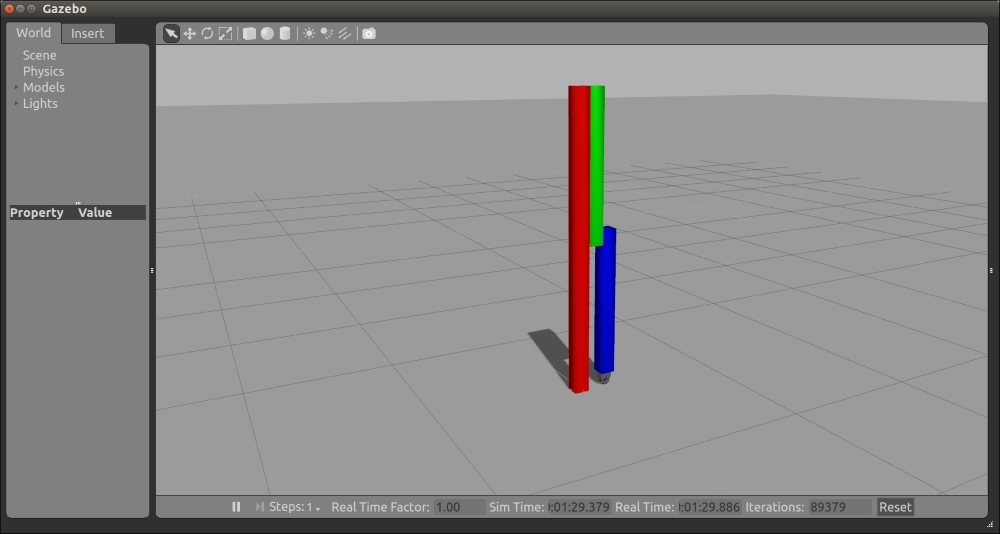
rrbot4.xacro in Gazebo
After verifying the model in Gazebo, additional control elements should be added to the robot arm URDF.
The following are the steps used to set up controls for this robot arm in the Gazebo simulation:
- Define transmission elements for joints in the
rrbotand gripper Xacro files. - Add a
gazebo_ros_controlplugin to our file of Gazebo-specific elements. - Create a YAML configuration file for control parameters.
- Create a control launch file to launch the robot joint controllers.
To begin with, we need to install four packages: gazebo_ros_pkgs, gazebo_ros_control, ros_control, and ros_controllers. The Gazebo_ros_pkgs metapackage is a set of ROS packages (a metapackage) that provides the interface and control for a robot in Gazebo. The Ros_control and ros_controllers packages provide generic controllers for ROS robots. For ROS Indigo, the Debian packages can be installed with the following command:
$ sudo apt-get install ros-indigo-gazebo-ros-pkgs ros-indigo-gazebo-ros-control ros-indigo-ros-control ros-indigo-ros-controllers
The gazebo_ros_control package integrates the ros_contol controller software with the Gazebo simulator. Gazebo_ros_control instantiates the ros_control (metapackage) controller_manager (package) to provide simulation of the robot's controllers. The controller manager will be used by our control launch file to spawn controllers for the joint_state_controller and controllers for all four of the robot arm's revolute joints.
More details on the ROS controllers and the ros_control packages can be found at http://wiki.ros.org/ros_control.
Specific elements must be added to the URDF/SDF in order for a model to be controlled in the Gazebo simulation environment. The <transmission> element is used to define the relationship between the robot joint and the actuator. These elements are supposed to encapsulate the details of the mechanical coupling, with specific gear ratios and parallel linkages defined. As you will note, we have a simple mechanical joint and do not require complex transmission element definitions.
The rrbot robot arm requires a <transmission> element for each of the rrbot revolute joints (joint_base_mid, joint_mid_top, left_gripper, and right_gripper). Each <transmission> element has a unique <name> and is associated with one of the <joint names> for the revolute joints. The <type> is transmission_interface/SimpleTransmission. In the <actuator> tag, the <hardwareInterface> is EffortJointInterface, since it is the only type implemented for Gazebo at the present time. Each of the four <transmission> element will look similar to the following code:
  <transmission name="transmission1">
    <type>transmission_interface/SimpleTransmission</type>
    <joint name="joint_base_mid">
      <hardwareInterface>EffortJointInterface</hardwareInterface>
    </joint>
    <actuator name="motor1">
      <hardwareInterface>EffortJointInterface</hardwareInterface>
      <mechanicalReduction>1</mechanicalReduction>
    </actuator>
  </transmission>
This code should be duplicated and added once each for the joint_base_mid and joint_mid_top in the rrbot4.xacro file. It should also be duplicated and added once each for the left_gripper and right_gripper in the gripper.xacro file.
More details on the <transmission> elements can be found at http://wiki.ros.org/urdf/XML/Transmission.
The gazebo_ros_control plugin defined previously in the Adding Gazebo-specific elements section is as follows:
  <!-- ros_control plugin -->
  <gazebo>
    <plugin name="gazebo_ros_control"
            filename="libgazebo_ros_control.so">
      <robotNamespace>/rrbot</robotNamespace>
      <robotSimType>
        gazebo_ros_control/DefaultRobotHWSim
      </robotSimType>
    </plugin>
  </gazebo>
This plugin will parse the <transmission> elements in the rrbot4.xacro and gripper.xacro files and load the identified hardware interfaces and controller managers. The preceding control plugin is a simple default plugin that should already be in the rrbot.gazebo file.
YAML is a markup language commonly used for ROS parameters. It is convenient to use YAML-encoded files to set ROS parameters on the Parameter Server. For rrbot, a YAML file is created to hold the joint controller configurations, and this YAML file is loaded via the control launch file. The controller type is defined for the joint_state_controller, as well as for all the four rrbot joint controllers. The four rrbot controllers also have proportional-integral-derivative (PID) gains defined. These PID gains have been tuned to the control of the rrbot arm and gripper. The rrbot_control.yaml file contains the following code:
rrbot:
  # Publish all joint states
  joint_state_controller:
    type: joint_state_controller/JointStateController
    publish_rate: 50

  # Position Controllers
  joint_base_mid_position_controller:
    type: effort_controllers/JointPositionController
    joint: joint_base_mid
    pid: {p: 100.0, i: 0.01, d: 10.0}
  joint_mid_top_position_controller:
    type: effort_controllers/JointPositionController
    joint: joint_mid_top
    pid: {p: 100.0, i: 0.01, d: 10.0}
  left_gripper_joint_position_controller:
    type: effort_controllers/JointPositionController
    joint: left_gripper_joint
    pid: {p: 1.0, i: 0.00, d: 0.0}
  right_gripper_joint_position_controller:
    type: effort_controllers/JointPositionController
    joint: right_gripper_joint
    pid: {p: 1.0, i: 0.00, d: 0.0}
The rrbot_control.yaml file should be saved to a /config directory under the ros_robotics package directory.
The best way to initiate control of our rrbot robot arm is to create a launch file to load the parameters into the Parameter Server and start all the ros_control controllers. The rosparam statement loads the controller settings to the Parameter Server from the YAML configuration file. Next, the control_spawner node creates the five controllers for rrbot using the controller_manager package. Another node is started for the robot_state_publisher. This rrbot_control.launch control file is shown as follows, and is stored in the /launch directory of the ros_robotics package directory:
<launch>

  <!-- Load joint controller configurations from YAML file to
            parameter server -->
  <rosparam file="$(find ros_robotics)/config/rrbot_control.yaml"
            command="load"/>

  <!-- load the controllers -->
  <node name="control_spawner" pkg="controller_manager"
    type="spawner" respawn="false"
    output="screen" ns="/rrbot" args="joint_state_controller
    joint_base_mid_position_controller
    joint_mid_top_position_controller
    left_gripper_joint_position_controller
    right_gripper_joint_position_controller"/>

  <!-- convert joint states to TF transforms for rviz, etc -->
  <node name="robot_state_publisher" pkg="robot_state_publisher"
    type="robot_state_publisher" respawn="false" output="screen">
    <remap from="/joint_states" to="/rrbot/joint_states" />
  </node>

</launch>
After the nodes are started, the joint_state_controller begins publishing all the (non-fixed) joint states of rrbot on the JointState topic. The robot_state_publisher subscribes to the JointState messages and publishes the robot's transforms to the tf transform library. Each of the other joint position controllers manages the control for its particular revolute joint.
To start the rrbot simulation, launch rrbot in Gazebo using the following command:
$ roslaunch ros_robotics rrbot_gazebo.launch
When rrbot is visible in the Gazebo window, open a second terminal window and launch the controllers using the following command:
$ roslaunch ros_robotics rrbot_control.launch
In the previously created control launch file, both the controller_manager and robot_state_publisher packages are used. If you plan to reuse this code or share it, it is recommended that you add these dependencies to your package.xml file for the ros_robotics package. The following statements should be added under the dependencies:
<exec_depend>controller_manager</exec_depend>
<exec_depend>robot_state_publisher</exec_depend>
Now, we are able to send commands via a third terminal window to control our rrbot robot arm. The rostopic pub command is used to publish our command data to a specific joint position controller.
This command will move the top link of the arm to a 1.57-radian (90-degree) position, relative to the middle link:
$ rostopic pub -1 /rrbot/joint_mid_top_position_controller/command std_msgs/Float64 "data: 1.57"
On the terminal, the following screen message is displayed:
publishing and latching message for 3.0 secondsOn the Gazebo screen, the rrbot arm should look similar to the following screenshot. The view has been rotated to make the arm more visible to the reader:
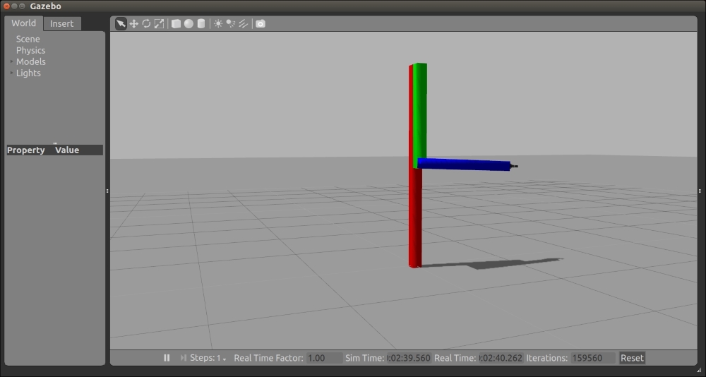
rrbot joint_mid_top at 1.57 radians
To open the gripper, two commands can be sent consecutively to move the right gripper and then the left gripper -0.5 radians from its center position:
$ rostopic pub -1 /rrbot/right_gripper_joint_position_controller/command std_msgs/Float64 "data: -0.5"; rostopic pub -1 /rrbot/left_gripper_joint_position_controller/command std_msgs/Float64 "data: -0.5"
On the Gazebo screen, the rrbot gripper should look similar to the following screenshot. Joint axes and rotation are shown in the Gazebo view:
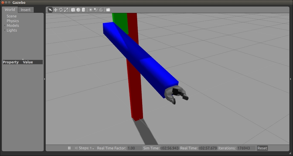
rrbot gripper open 1.0 radians
Another tool that we can use to control our rrbot arm is rqt, the ROS plugin-based user interface described in the Introducing RQT tools section of Chapter 3, Driving Around with TurtleBot. The command to start rqt is as follows:
$ rosrun rqt_gui rqt_gui
Under the Plugins menu on the rqt main window menu bar, select the Topic | Message Publisher plugin. From the Topic drop-down box, at the top of the Message Publisher plugin, select the command for the particular controller that you want to publish to and add it to the Message Publisher main screen. The green plus sign button in the top-right corner of the window will add the command to the main screen. In the following screenshot, the /rrbot/joint_base_mid_position_controller/command and the /rrbot/joint_mid_top_position_controller/command topics have been added to the Message Publisher main screen:
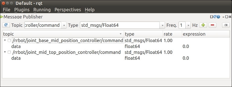
rqt Message Publisher screen for rrbot
To change the position of the rrbot arm, select and change the expression field of one of the topics. In the following screenshot, the value of the /rrbot/joint_base_mid_position_controller has been changed to -1.57 radians. In addition to this, the plugin for the Topic Monitor has been displayed so that the change in the published state of the /rrbot/joint_base_mid_position_controller can be verified:
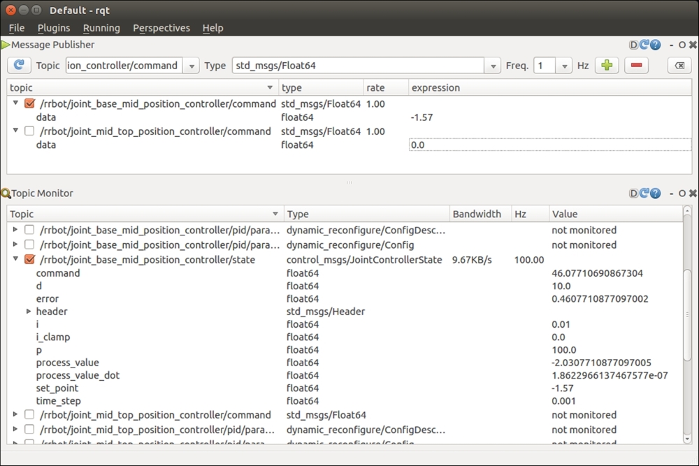
rqt Message Publisher and Topic Monitor
The following screenshot shows both rqt and Gazebo with the rrbot arm positioned with its joint_base_mid at -1.57 radians. The joint_mid_top is set at 0.0 radians:
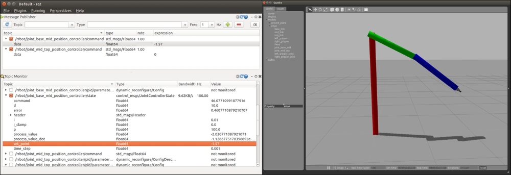
rrbot arm controlled via rqt
The following suggestions are additional starting points for using rqt with your rrbot arm:
- Message Publisher expression values can also be equations, such as sin(i/10), where i is an rqt variable for time. Inserting this equation into one of the joint commands will make the joint vary sinusoidally with respect to time.
- The rqt Plot plugin is found under Plugins | Visualization | Plot. Choose to plot the
joint_xxx_position_controller/command/datato the screen or even thejoint_xxx_position_controler/state/error. The error plot will visually display how well the PID control eliminates the error on the joint. - The rqt Dynamic Reconfigure plugin is found under Plugins | Configuration | Dynamic Reconfigure. Click on Expand All to see all the options and select PID for any of the joint controllers. A pop-up window will allow you to dynamically change the p_gain, i_gain, d_gain, i_clamp_min, and i_clamp_max to tune that controller's performance.
It is also possible to move the robot arm with a Python script, but this is left as an exercise for the reader.