
In this chapter, we will take a look at the pulse width modulation (PWM) and analog-to-digital converter (ADC) subsystems. We will cover the following topics:
- Fading an LED
- Controlling servo motors
- Voltage dividers
- Voltage followers
- Sensing light levels with a photocell
- Sensing distance with Sharp IR rangefinders
- Building a simple robot
The BeagleBone's PWM subsystem contains three enhanced PWM (ePWM) modules and one enhanced capture (eCAP) module, all of which have their own two outputs, for a total of up to eight PWM outputs (refer to Appendix A, The BeagleBone Black Pinout to see which pins support PWM). We briefly covered what PWM is in Chapter 1, Before We Begin, but let's look at it in a bit more detail before we start using it.
For this, you will need:
- Breadboard
- 1x 5 mm LED
- 1x 4.7 kΩ resistor
- 1x 68 Ω resistor
- 1x 2N3904 NPN transistor
- Jumper wires
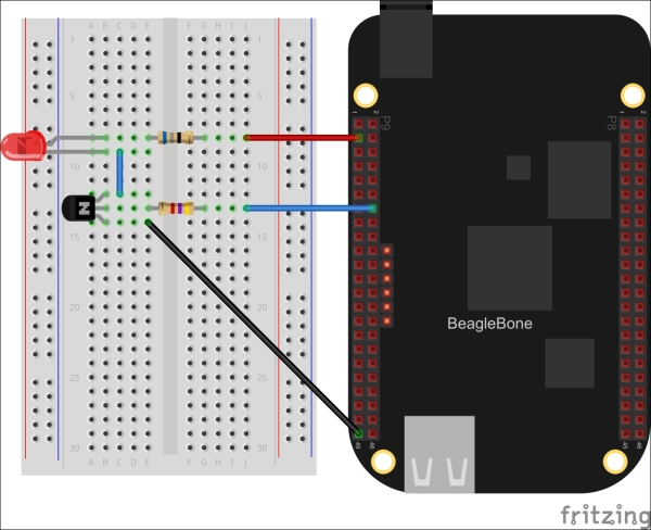
Let's start by wiring up an LED with an NPN transistor as we did in Chapter 3, Digital Outputs; only this time, we will drive it with the ePWM1 module's 'A' output on P9.14:
Now let's fire up the Python interactive interpreter and configure the PWM output at 50 percent duty cycle:
>>> from bbio import *
>>> analogWrite(PWM1A, 50, 100)
You should see the LED turn on, but dimmer than if you had driven it with a GPIO pin. So what's going on here? The analogWrite() function is used to set the duty cycle of the output signal, and in this case, we've told it to drive the output high for 50/100 or 50 percent of the cycle. This percentage is called the duty cycle. Let's take a look at the signal now being generated on the PWM1A pin with an oscilloscope:
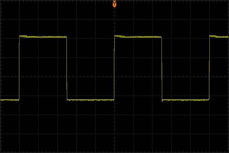
You might be wondering why you can't see the LED blinking on and off; the actual frequency of the output defaults to 10 KHz in PyBBIO, or 2 KHz in Adafruit_BBIO, meaning there are 10,000 or 2,000 of these half-on half-off cycles every second respectively. Those changes are much faster than the human eye can perceive, so we just see it as being dimmer.
Now let's set the output down to 10 percent:
>>> analogWrite(PWM1A, 10, 100)
And here's what a 10 percent duty cycle looks like on the oscilloscope:
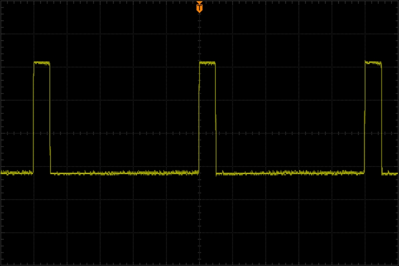
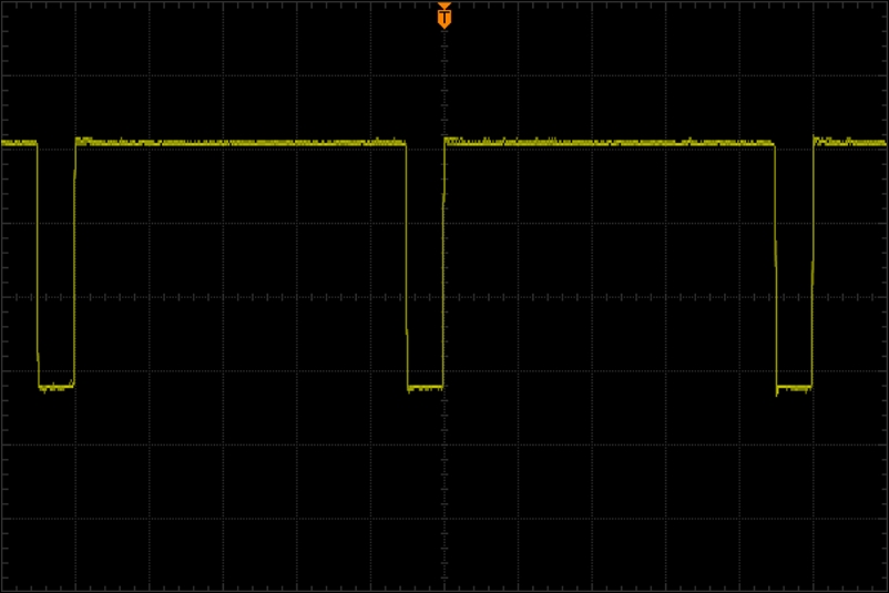
With the LED only lit for 10 percent of the cycle, we perceive it as being dimly lit. Now if we go up to a 90 percent duty cycle, the LED looks much brighter:
>>> analogWrite(PWM1A, 90, 100)
And, as expected, we can see on the oscilloscope that the signal is high for 90 percent of its period:
The first time the analogWrire() function is called it automatically enables the the PWM subsystem and configures the pin multiplexer for PWM output by loading Device Tree overlays using the capemgr driver.
Try out this example program with the same transistor-LED circuit as before, which will fade the LED up and down forever:
from bbio import *
led_pin = PWM1A
def setup():
  pass
  def loop():
    for level in range(0, 255, 5):
      analogWrite(led_pin, level)
      delay(10)
    for level in range(255, 0, -5):
      analogWrite(led_pin, level)
      delay(10)
run(setup, loop)
As you can see, we're going all the way up to a PWM value of 255 this time, and we've left out the third argument to the analogWrite() function. That third argument is optional, and defines the resolution being used. It defaults to 256 to be consistent with the Arduino analogWrite() routine, but it can be any number, for instance, 100 to specify values in percent. The BeagleBone's PWM modules use 16-bit timers, so the actual maximum resolution is 216 or 65536.
Now let's take a look at how PWM is used in Adafruit_BBIO:
import time
from Adafruit_BBIO import PWM

led_pin = "P9_14"
PWM.start(led_pin, 0)

try:
  while True:
    for level in range(0, 100):
      PWM.set_duty_cycle(led_pin, level)
      time.sleep(0.01)
    for level in range(100, 0, -1):
      PWM.set_duty_cycle(led_pin, level)
      time.sleep(0.01)
except KeyboardInterrupt:
  PWM.cleanup()
The second argument passed PWM.start() is the initial duty cycle. Adafruit_BBIO also lets you change the PWM frequency, which it sets to 2 kHz by default, by passing the desired frequency in Hz as a third argument to PWM.start(). The Adafruit_BBIO PWM outputs are set by their duty cycle in percent, so PWM.set_duty_cycle() takes values in the range 0–100, which can float point numbers for higher resolutions. Like with PyBBIO, the first time PWM.start() is called the appropriate Device Tree overlays will be loaded.
A common device that is controlled by PWM is the servo motor. Standard micro servos, such as the Tower Pro SG92R, are readily available at stores such as SparkFun and Adafruit, and are a cheap and easy way to get things moving. Let's take a look at controlling a micro servo from the BeagleBone.
For this, you will need:
- Breadboard
- 1x 1 kΩ resistor
- 1x 0.1 µF capacitor
- 1x micro servo motor
- Jumper wires
Wire the servo to the BeagleBone's 5 V supply, and connect the signal wire to PWM1A through a 1 kΩ resistor:
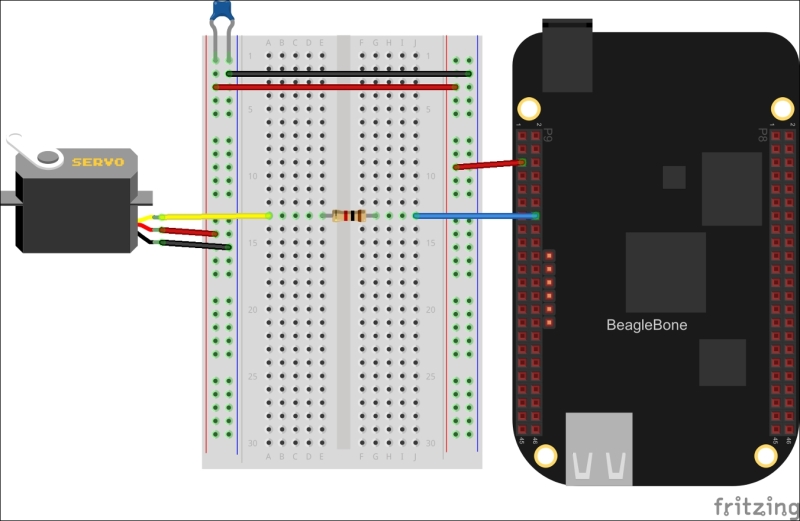
Note
The BeagleBone P9 header has two different 5 V supplies. P9.5 and P9.6 are connected directly to the DC barrel jack, and P9.7 and P9.8 are connected to the output of the BeagleBone's on-board voltage regulator. If you are powering your BeagleBone from the DC barrel jack, it is best to use P9.5 and P9.6 as you will be able to draw more current. If you are powering the BeagleBone through the USB jack you will have to use P9.7 and P9.8 instead, in which case your connected devices cannot draw more than 250 mA.
The 1 kΩ resistor ensures that the servo can't draw too much current from the PWM pin.
The 0.1 µF (0.1 microfarad) capacitor across the power supply is being used as what's called a bypass capacitor. One of the properties of capacitors is that they pass high frequency signals and block low-frequency and DC signals. A bypass capacitor essentially shorts any high frequency signals that may be coupled on the power supply to ground, leaving a clean DC supply. It is not necessarily required as the BeagleBone has its own bypass capacitors on board, but it is advised as we are adding a servo motor, which can draw quick pulses of current and couple high frequency signals onto the supply.
A servo motor can typically only rotate 180 degrees at most, and it will position itself at a given angle depending on the width of the positive pulse of the input signal. Typically, they require an input signal of around 50 Hz, with a positive pulse of around 0.5 ms for 0 degrees and up to around 2.4 ms for 180 degrees. With the motor connected, let's launch the Python interpreter and give it a go.
First, let's set the frequency of the ePWM1 module to 50 Hz:
>>> from bbio import *
>>> pwmFrequency(PWM1A, 50)
We could figure out the duty cycles as percentages for the desired pulse widths, or to make it easier, we can just use the period of a full cycle as our resolution period = 1 / 50, Hz = 0.02, and s = 20 ms. So to set the positive pulse to 0.5 ms, we can use the following command line:
>>> analogWrite(PWM1A, 0.5, 20)
To set it to 180 degrees, use the following command line:
>>> analogWrite(PWM1A, 2.4, 20)
You will likely find that your motor has slightly different extremes than 0.5 ms and 2.4 ms, so you should use the interpreter to find the lowest and highest values that make the motor move by trial and error and take note of them.
To drive a servo motor from Adafruit_BBIO, you'll need to convert the pulse widths to percentages. As we just calculated, with a frequency of 50 Hz, the period of each cycle will be 20 ms. As the duty cycle is the percentage of the period during which the output is in a high state, we can calculate it by dividing the desired pulse width by the period, for example, 0.5 ms / 20 ms = 0.025. This will give us a value in the range of 0–1, so we then just need to multiply by 100 to get a percentage for PWM.set_duty_cycle(). As an example, here's a program that will alternate the motor between its minimum and maximum rotation angles:
import time
from Adafruit_BBIO import PWM

servo_pin = "P9_14"
servo_min = 100*0.5/20.0
servo_max = 100*2.4/20.0

PWM.start(servo_pin, 0, 50)

try:
  while True:
    PWM.set_duty_cycle(servo_pin, servo_min)
    time.sleep(2)
    PWM.set_duty_cycle(servo_pin, servo_max)
    time.sleep(2)
except KeyboardInterrupt:
  PWM.cleanup()
Again, you will most likely need to replace the 0.5 and 2.4 values with the extremes you found for your motor.
PyBBIO also includes a library specifically for servo motors, so you don't actually need to deal with changing the frequency and figuring out the duty cycles for the angles you want to set them to. This is provided as a Servo class in the bbio.libraries.Servo module, as shown in the following code;
from bbio import *
from bbio.libraries.Servo import Servo

motor = Servo(PWM1A)

def setup():
    pass

def loop():
    for i in range(0, 180):
        motor.write(i)
    for i in range(180, 0, -1):
        motor.write(i)

run(setup, loop)
When you run this example, you should see your servo motor sweep back and forth. If you found that you have different minimum and maximum pulse widths than the default 0.5 ms and 2.4 ms, you can specify them when you instantiate the Servo() object, for example:
motor = Servo(servo_pin, min_ms=0.8, max_ms=2.2)