
In the I2C protocol, there's a master device controlling one or more slave devices using two digital signals. One of the signals is a clock, called Serial Clock (SCL), and the other is a bidirectional data line, called Serial Data (SDA). The clock signal is generated by the master, which means the devices don't need to be programmed with the same symbol rate like UARTs do.
To handle multiple devices, each slave device on the same bus (sharing the same SDA and SCL signals) must have an individual address. The standard I2C protocol uses 7-bit slave addresses, meaning there can be up to 27 = 128 devices on a single bus. There are 16 addresses reserved for special purposes, so that leaves room for 112 general I2C devices per bus. A device's address is programmed into it by its manufacturer, and there is no guarantee that any two devices won't have the same address, so in practice, the upper limit would likely be less than 112. Some devices have a single hardcoded address and some devices can be set to one of a few hardcoded addresses by pulling external address pins high or low.
When the I2C master wants to communicate with a slave device, it must first send a header, which includes the address of the device it wants to communicate with, as well as a bit, called the R/W bit, which tells the slave if the master is intending to write data to it or read data from it. To send these bits, the master pulls the clock line low, sets the data line according to the current bit value, sets the clock line high, and then repeats for each subsequent bit. The slave device reads the state of the data line when it detects the rising edge of the clock line. Once the address and R/W bit have been sent, the master sets its data pin to an input state and the slave device sets its data pin to an output state. When the slave device detects the next falling clock edge from the master, it sets the data line high to indicate it has acknowledged the packet, or sets it low to indicate that it has not acknowledged it. This is referred to as an ACK or NACK, respectively. If the R/W bit is 1, meaning that the master will be writing to the device, the data line once again is controlled by the master and the data is written one byte at a time, with each byte concluding with the ACK/NACK bit from the slave. If the R/W bit is 0 to indicate read mode, the slave remains in control of the data line, shifting bits out as the master toggles the clock line.
There are a few clock rates defined for I2C buses—100 kilobit/s standard speed, 400 kilobit/s full speed, 1 megabit/s fast mode, and 3.2 megabit/s high speed. The BeagleBone I2C buses all operate at the 100 kilobit/s standard speed.
The BeagleBone Black has two I2C buses available on its expansion headers:
- I2C1
- SCL - P9.17
- SDA - P9.18
- I2C2
- SCL - P9.19
- SDA - P9.20
There is an additional I2C0 bus on the BeagleBone Black, but it is used for communication between onboard ICs and is not accessible on the expansion headers.
The three I2C buses are controlled through the /dev/i2c-0, /dev/i2c-1, and /dev/i2c-1 device nodes. The BeagleBone Black's kernel numbers the I2C buses in the order in which they appear, and these numbers don't correspond to the actual bus numbers. However, I2C0 and I2C2 are both enabled by default (I2C2 is used to detect expansion capes), and are therefore controlled through /dev/i2c-0 and /dev/i2c-1, respectively. I2C1 can be enabled by loading the BB-I2C1 Device Tree overlay, which creates the next device node /dev/i2c-2. So to summarize, /dev/i2c-0 controls I2C0 (used internally and should be left alone), /dev/i2c-1 controls I2C2, and /dev/i2c-2 controls I2C1 (when enabled with capemgr). When using PyBBIO, the I2C1 overlay is loaded automatically if it is being used, and you don't need to worry about the device node numbering. With Adafuit_BBIO, you will have to remember the numbering scheme because the port being used is specified by the device node numbering.
Let's look at an example of using an I2C bus by hooking up a Melexis MLX90614 contactless IR temperature sensor (http://www.adafruit.com/products/1747) to the I2C2 bus.
Note
The MLX90614 is a fairly pricey sensor, and we won't go very deep into software for it, so there's no real need to follow along. If you are building the circuit up for yourself, though, make sure to use the 3 V version of the sensor and not the 5 V version; otherwise, you could damage the sensor and/or your BeagleBone.
The circuit is pretty simple:
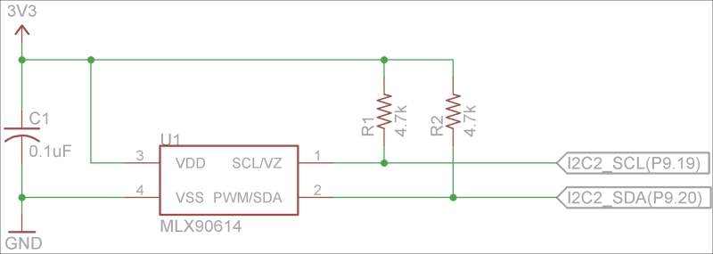
As you can see, there are two pull-up resistors on the SCL and SDA lines. These are a requirement of the I2C protocol, and it won't function without them. The pull-up on the SDA line ensures that it will be at a high level during the transition between master and slave control, and the pull-up on the SCL line will ensure that there are no false clock pulses if the master device gets reset.
There is also a suite of command line tools to help with using I2C from user-space on GNU/Linux called i2c-tools, which you can install from apt-get on Debian:
# apt-get install i2c-tools
One of these tools is i2cdetect, which is able to probe I2C buses for slave devices. With the MLX90614 hooked up to I2C2, we can run the tool and find its address:
root@beaglebone:~# i2cdetect -r 1
WARNING! This program can confuse your I2C bus, cause data loss and worse!
I will probe file /dev/i2c-1 using read byte commands.
I will probe address range 0x03-0x77.
Continue? [Y/n] y
     0  1  2  3  4  5  6  7  8  9  a  b  c  d  e  f
00:          -- -- -- -- -- -- -- -- -- -- -- -- --
10: -- -- -- -- -- -- -- -- -- -- -- -- -- -- -- --
20: -- -- -- -- -- -- -- -- -- -- -- -- -- -- -- --
30: -- -- -- -- -- -- -- -- -- -- -- -- -- -- -- --
40: -- -- -- -- -- -- -- -- -- -- -- -- -- -- -- --
50: -- -- -- -- UU UU UU UU -- -- 5a -- -- -- -- --
60: -- -- -- -- -- -- -- -- -- -- -- -- -- -- -- --
70: -- -- -- -- -- -- -- --
This table tells us that the MLX90614 has an address of 0x5a (which we can also find in the datasheet), and is connected and responding properly. The datasheet tells us that we can read the temperature of the object the sensor is pointing at by first writing the command 0x07 to it, then by reading the three bytes. We can also read the ambient temperature inside the sensor the same way, but instead using the 0x06 command.
PyBBIO provides two objects, I2C1 and I2C2, for controlling the I2C buses. The full I2C API can be found on the PyBBIO wiki page at https://github.com/graycatlabs/PyBBIO/wiki/I2C. It is common for I2C devices to use the protocol of writing a byte before reading, so that it knows what to send (which can correspond to a command, as with the MLX90614, or it can be the address of a register in the slave device's memory, which you want to access); so along with the individual read() and write() methods, PyBBIO also provides a method called readTransaction(), which does just that. So to read the temperature from the device we will first enable the bus:
root@beaglebone:~# python
Python 2.7.3 (default, Mar 14 2014, 17:55:54)
[GCC 4.6.3] on linux2
Type "help", "copyright", "credits" or "license" for more information.
>>> from bbio import *
PyBBIO initialized
>>> I2C2.open()
Then, we will call readTransaction(), giving it the address of the MLX90614, the 0x07 command byte to write, and the number of bytes to read:
>>> I2C2.readTransaction(0x5a, 0x07, 3)
[41, 58, 179]
The first two bytes received are the low and high bytes of the measured temperature, respectively. The third byte received is an 8-bit cyclic redundancy check (CRC-8) calculated from the temperature data, which can be used to detect whether the data was corrupted due to transmission errors.
Let's take a look at the SDA and SCL signals when we read the temperature:
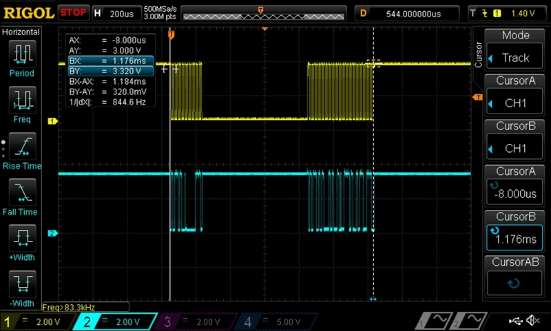
The top trace in the capture is the SCL signal and the bottom is SDA. You can distinctly see the separate write and read sections of the transaction. Let's take a closer look at the first section:
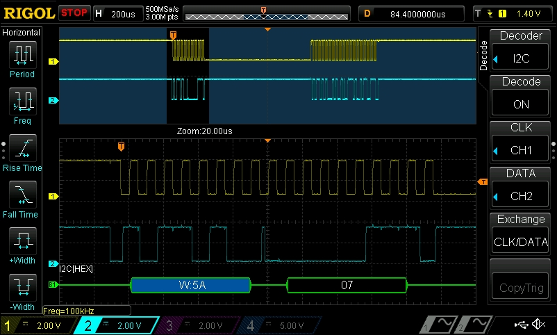
The first thing sent is the address, with the R/W bit set to write, followed by the 0x07 command. Also notice that the bytes are being sent in the MSB first order, as opposed to the LSB first order that the UARTs use. Now we'll zoom in on the second section:
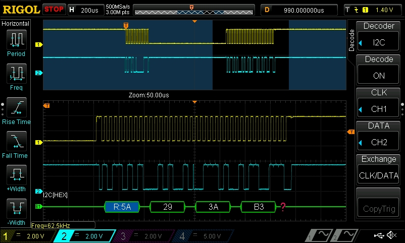
The second part of the transaction is started with another header, but this time with the R/W bit set to read, then the three data bytes are received. As soon as the header is sent, the MLX90614 takes control of the SDA line.
For the sake of completeness, here's a small program to show you how the two temperatures can be read and converted from the MLX90614 using PyBBIO:
from bbio import *

def readObjectTempC():
    low, high, pec = I2C2.readTransaction(0x5a, 0x07, 3)
    tempk = ((high << 8) | low)*0.02 # temp in Kelvin
    return tempk - 273.75 # Convert to Celsius

def readAmbientTempC():
    low, high, pec  = I2C2.readTransaction(0x5a, 0x06, 3)
    tempk = ((high << 8) | low)*0.02
    return tempk - 273.75

def setup():
    I2C2.open()

def loop():
    print "ambient = {:0.2f} C - object = {:0.2f} C".format(
            readAmbientTempC(),
            readObjectTempC()
            )
    delay(500)

run(setup, loop)
Adafruit_BBIO provides the Adafruit_I2C class, which is fully documented at https://learn.adafruit.com/setting-up-io-python-library-on-beaglebone-black/i2c. You'll first need to install the python-smbus package that it depends on:
# apt-get install python-smbus
Adafruit_BBIO uses a slightly different abstraction than PyBBIO for I2C, where the Adafruit_I2C object is instantiated with the address of a remote device. In other words, there is one Adafruit_I2C instance per slave device, as opposed to PyBBIO's I2C1 and I2C2 objects, which each represent an entire I2C bus. Reading the temperature from the MLX90614 with Adafruit_BBIO would look like this:
from Adafruit_I2C import Adafruit_I2C
i2c = Adafruit_I2C(0x5a, 1) # bus 1 for /dev/i2c-1, or I2C2
data = i2c.readList(0x07, 3)