
SPI is, in its most typical form, a 4-wire protocol. Like I2C, it is a single-master, multiple-slave protocol. It has a clock line (SCK), a data line from the master to the slaves (MOSI), a data line from the slaves to the master (MISO), and a separate chip select (CS) line for each slave device. The CS signal for a particular slave device is pulled low by the master before communicating with it, and any other device on the same bus with its CS line set high will ignore any transferred data. SPI requires more pins than I2C, but unlike I2C it doesn't require transactions to include a slave address header, and it has separate data lines for each direction of communication (which can transfer data simultaneously). For these reasons, it can typically achieve higher data rates than I2C. The number of devices that can be put on the same SPI bus is dictated by the number of available pins for CS signals.
The SPI protocol is less strictly defined than I2C, with the bit order, clock mode, and clock speed all being configurable. The clock mode is made up of two bits, the clock polarity (CPOL) bit and the clock phase (CPHA) bit. These bits are as follows:
- CPOL=0: SCK is idle low (low level when no data is being sent)
- CPHA=0: Data bits are set on the SCK falling edge and read on the SCK rising edge
- CPHA=1: Data bits are set on the SCK rising edge and read on the SCK falling edge
- CPOL=1: SCK is idle high
- CPHA=0: Data bits are set on the SCK rising edge and read on the SCK falling edge
- CPHA=1: Data bits are set on the SCK falling edge and read on the SCK rising edge
A particular SPI device will specify the clock settings it uses, and it's up to the master device to ensure that it sets the clock mode accordingly. An SPI master can communicate with slave devices that have different clock modes on the same bus by simply changing the clock mode between interactions with each device.
There are no real standard SPI clock speeds, and SPI devices typically specify their maximum supported clock frequency. The device with the slowest maximum frequency on an SPI bus dictates the maximum bus speed.
The BeagleBone Black has two SPI ports available on its expansion headers, SPI0 and SPI1, with the pins:
- SPI0:
- CS0 - P9_17
- MISO - P9_21
- MOSI - P9_18
- SCLK - P9_22
- SPI1:
- CS0 - P9_28
- CS1 - P9_42
- MISO - P9_29
- MOSI - P9_30
- SCLK - P9_31
Note
You'll have to disable HDMI to use SPI1, as described in Appendix B, Disabling HDMI.
The SPI modules are enabled by loading Device Tree overlays with capemgr, called BB-SPIDEV0 and BB-SPIDEV1. These create the device nodes /dev/spidev1.0, /dev/spidev1.1, /dev/spidev2.0, and /dev/spidev2.1. The first number in each device name corresponds to an SPI bus, while the second number corresponds to a CS signal. As for I2C, the bus number in the device nodes is assigned according to the order in which the buses are enabled. Neither SPI bus is enabled by default, so you'll have to keep track of the order in which you enable them. Again, if you're using PyBBIO, this is kept track of behind the scenes for you.
Since SPI0 only has its CS0 signal exposed on the headers, and not its CS1 signal, the /dev/spidevX.1 device node corresponding to SPI0 will not control any external CS signal on the expansion headers. If you need more than two devices connected to one of the SPI buses, you can simply use GPIO pins for chip select signals instead.
In PyBBIO, initializing an SPI bus is similar to I2C or UART:
root@beaglebone:~# python
Python 2.7.3 (default, Mar 14 2014, 17:55:54)
[GCC 4.6.3] on linux2
Type "help", "copyright", "credits" or "license" for more information.
>>> from bbio import *
PyBBIO initialized
>>> SPI0.open()
It's also good to set your clock frequency to a known value to make sure you're not running faster than any of the connected devices support, for example 1 MHz:
>>> SPI0.setMaxFrequency(0,1000000)
To then write out a byte of data, would be as follows:
>>> SPI0.write(0, [0x61])
Where the first number is the CS signal to use and the second is a list of bytes to be sent sequentially. We can see this transmission in action on the oscilloscope:
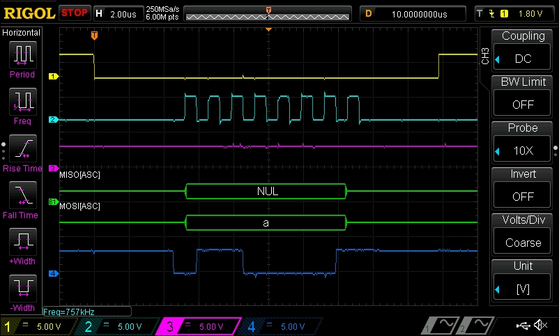
The top yellow trace is the CS signal, which you can see being pulled low at the start of the transmission and driven high at the end. The light blue trace below it is the clock signal. The default clock mode for the BeagleBone Black's SPI modules is CPOL = 0 and CPHA = 0, so the clock is idle and low and the data is read on the rising edge (the clock mode can be configured with the setClockMode() method). The clock signal has eight rising edges for the eight bits in the byte we sent. The pink trace is the MISO line, the data being received by the master, and it is unchanged since there's no data being received. The dark blue trace at the bottom shows the bits sent on the MOSI line, and the SPI decoder shows that it is the ASCII character "a" as expected.
As a quick test to make sure we are receiving data as expected, we can simply connect the MOSI and MISO signals to create a data loopback. If we do this and send a few more bytes, as follows:
>>> SPI0.transfer(0, [0x61, 0x62, 0x63])
[97, 98, 99]
Then, we can see that the data with the same bytes is received (which are integers, so Python prints them as decimal values). Let's take a look at the oscilloscope when we send this sequence:
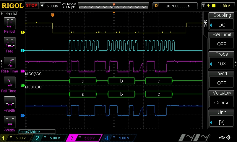
As you can see, the same data is now present on the MISO line because we connected it to MOSI. We can also see that the CS line is held low for the entire transmission instead of toggled between bytes.
As mentioned previously, to use SPI from Adafruit_BBIO, you'll need to first load the BB-SPIDEV0 or BB-SPIDEV1 Device Tree overlay. You'll then need to take note of the bus number assigned to the spidev device node entry that was created. If you're only using one SPI bus, this will be 1 for /dev/spidev1.x. You then need to create an instance of the Adafruit_BBIO.SPI class for each bus and CS pin you are using. Adafruit_BBIO numbers the buses starting from 0, so to use SPI1 with CS0 it will be:
from Adafruit_BBIO.SPI import SPI
spi = SPI(0,0)
spi.writebytes([0x61])
The documentation for the Adafruit_BBIO SPI class can be found at https://learn.adafruit.com/setting-up-io-python-library-on-beaglebone-black/spi.