
We just calculated that a 68 Ω resistor will give us the maximum forward current from a 3.3 V supply, but when we hooked up the LED to the 3.3 V GPIO pin earlier, we used a 330 Ω resistor. This is because the GPIO pins of BeagleBone's processor are only rated to source a maximum current of 4-6 mA. Using a 330 Ω resistor gives 1.3 V / 330 Ω = 3.9 mA.
There are a few ways we can source more current than the 4-6 mA maximum of the GPIO pins; one simple way is to use an NPN Bipolar Junction Transistor (BJT).
For this circuit, you will need:
- Breadboard
- 1x 5 mm LED
- 1x 4.7 kΩ resistor
- 1x 68 Ω resistor
- 1x 2N3904 NPN transistor
- Jumper wires
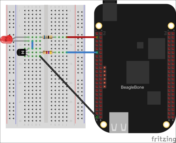
Wire it up on your breadboard as shown here:
Note
If you have a resistor kit like the one from SparkFun (https://www.sparkfun.com/products/10969) you might not have a 68 Ω resistor handy. If this is the case, you can use one 220 Ω resistor in parallel with one 100 Ω resistor for a combined resistance of 68.75 Ω.
Let's take a quick look at a schematic for this circuit:
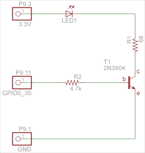
There is tons to be learned about transistors, but in this case, we're essentially using it as a switch, and we can treat it as a black box. When the GPIO pin is set to its 0 V low state, no current flows into the base of the transistor (marked b in the schematic), which prevents any current from flowing between the collector (c) and the emitter (e). When the GPIO pin is set high, enough current flows through R2 into the base of the transistor to allow it to pass a larger current (by a current gain factor, which is a specified parameter of the specific transistor being used) from the collector (c) to the emitter (e), and therefore, through the LED1 and R1. This basically allows you to switch on and off the current flowing through the LED directly from the 3.3 V power supply, and the 68 Ω resistor limits it to the 20 mA we need.
If you put an ammeter in series with the LED and measure the current through it, you will see that it is actually a bit lower than 20 mA. This is because there is a slight voltage across the transistor's collector and emitter. This voltage drop is proportional to the current, so it can be tricky to calculate the exact resistor value needed, but with an ammeter and a bit of trial and error, you can narrow it down to a good value. A 56 Ω resistor should give around 19.5 mA with the 2N3904.