
The BeagleBone has 7 available inputs to its analog-to-digital converter (refer to Appendix A, The BeagleBone Black Pinout to see which pins support analog inputs). The ADC can approximate voltages at each of these pins between 0 V and 1.8 V. As mentioned in Chapter 1, Before We Begin, putting voltages greater than 1.8 V on any of the ADC's input pins will damage your BeagleBone. That doesn't mean we can't measure higher voltages with it, we just need some external circuitry to do so.
The simplest method for measuring voltages greater than 1.8 V is to use a voltage divider, which is simply composed of two resistors in a series between your voltage source and 0 V, with the output being the node between them:
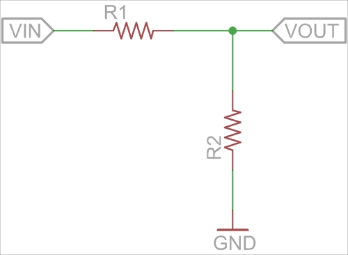
The output voltage is calculated by the formula R2 / (R1 + R2) * VIN. So if VIN is 3.3 V and both resistors are 10 kΩ, then VOUT will be 1.65 V, and if VIN is 5 V, R1 is 10 kΩ, and R2 is 5 kΩ, then VOUT will be 1.67 V. So with those two examples, we could easily monitor the BeagleBone's 5 V and 3.3 V supplies using the on board ADC, and we could simply compensate for the divider in software by multiplying the measured voltages by two and three respectively. Let's give it a try.
For this, you will need:
- Breadboard
- 3x 10 kΩ resistor
- 1x 4.7 kΩ resistor
- Jumper wires
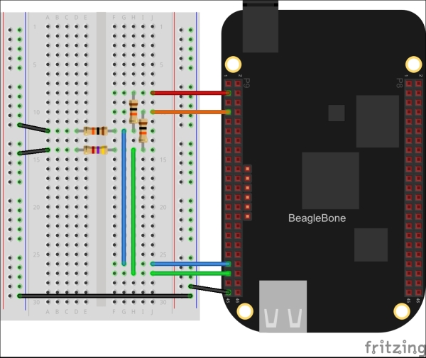
Use two of the 10 kΩ resistors to divide the 3.3 V supply by two and then wire that into the AIN4 ADC input (P9.33), and use the other 10 kΩ and 4.7 kΩ resistors to divide the 5 V supply and wire that to the AIN6 ADC input (P9.35). As mentioned earlier, using 10 kΩ and 5 kΩ resistors will divide the 5 V supply by 3, but 5 kΩ is not a standard resistor value so we'll use 4.7 kΩ instead. Wire up the circuit like so:
Now hop into the Python interactive interpreter, and let's try reading the voltages:
>>> from bbio import *
>>> analogRead(AIN4)
1692
The return value of analogRead() will be the voltage in millivolts present on the given analog input pin. You can convert this to volts with the PyBBIO's inVolts() function. Then you just multiply the voltage appropriately to get the voltage present on the input of the voltage divider:
from bbio import *

v_5v = inVolts(analogRead(AIN5)) * (4.7 + 10)/4.7
v_3v3 = inVolts(analogRead(AIN4)) * 2.0
print "5V input = {:0.2f}".format(v_5v)
print "3.3V supply = {:0.2f}".format(v_3v3)
In PyBBIO the ADC is automatically enabled with a Device Tree overlay the first time you call analogRead(). Adafruit_BBIO also loads the ADC overlay for you, but you have to explicitly call the ADC.setup() function to tell it to do so:
from Adafruit_BBIO import ADC

ADC.setup()
v_5v = 1.8 * ADC.read("P9_35") * (10 + 4.7)/4.7
v_3v3 = 1.8 * ADC.read("P9_33") * 2.0
print "5V input = {:0.2f}".format(v_5v)
print "3.3V supply = {:0.2f}".format(v_3v3)
Also, as you can see, we're multiplying the value by 1.8. This is because the ADC.read() function of Adafruit_BBIO returns the value as a ratio of the ADC's 1.8 V reference voltage. Multiplying the returned value by 1.8 gives us the measured voltage in volts.
The voltage divider is great for measuring DC supplies and the buffered outputs of powered sensors, but because it is just a simple resistive network, it doesn't play well with other devices and circuits that have series resistances in the same order of magnitude. For example, you might want to monitor the current that your LED is drawing from one of the circuits, as we did in Chapter 3, Digital Outputs.
As mentioned earlier, the voltage follower doesn't work well when the input is coming from another circuit with low resistances in its path (known as low impedance outputs), as they will form a more complex resistor network and affect the output voltage. One way to avoid this problem is to use a voltage follower (or buffer) to isolate the two circuits.
There are a number of ways to make voltage followers, but we'll use one of the simplest, which is made with just a single stage of an operational amplifier (or op-amp), as shown in the following schematic:
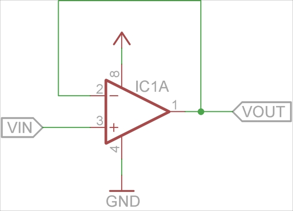
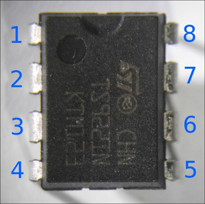
The op-amp's connections in the schematic are labeled as per the standard pinout for an 8-pin dual op-amp, which is one of the most common op-amp packages. The pin numbers follow the standard numbering for dual in-line package (DIP) integrated circuits, where the pins are numbered from 1 onwards in a U pattern starting at the top left (pin 1 is typically marked by a dot and/or half circle), as seen in the image:
The basic idea of the voltage follower is that it has high input impedance, meaning that there is a very large resistance between the input and ground, and it has low output impedance, meaning that there is a very low resistance in a series with the output. This means that we can put just about anything on the input side, and a voltage divider on the output side won't interfere with it. Let's look at a circuit that uses a voltage follower.
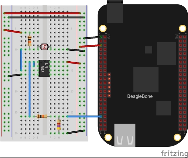
For this, you will need:
- Breadboard
- 1x CdS photocell (also known as photoresistor / light-dependant resistor / LDR)
- 2x 10 kΩ resistor
- 1x 4.7 kΩ resistor
- 1x LM358 (or similar rail-to-rail op-amp)
- Jumper wires
We will be wiring up the op-amp as shown in the schematic:
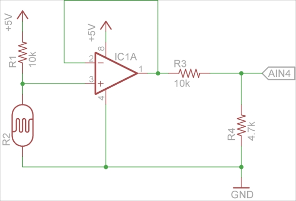
In this circuit, we're using a photocell (R2), which is just a resistor whose resistance varies with light. If there is a voltage across a photocell and its resistance changes with the light, the current passing through the photocell will also change. The BeagleBone's ADC can only measure voltages, so we use a 10 kΩ resistor (R1) to create a voltage that varies with the light (it's another voltage divider). This photocell circuit is being powered by a higher voltage than the ADC's 1.8 V maximum, so we need to divide the voltage from the sensor. The voltage follower made with the LM358 op-amp isolates the two circuits so they don't interfere with each other. Let's have a look at the following figure:
Wire up the circuit and run this program to print the voltage across the photocell, and you should see the voltage changing as you move your hand in front of the sensor or shine a light on it. Let's have a look at the following code:
from bbio import *

ldr_pin = AIN4

def setup():
    pass

def loop():
    vin = inVolts(analogRead(ldr_pin))
    vin *= (10 + 4.7)/4.7
    print "voltage across LDR: {:0.2f}V".format(vin)
    delay(500)

run(setup, loop)
You could do the same in Adafruit_BBIO with the following code:
import time
import Adafruit_BBIO.ADC as ADC

ADC.setup()
while True:
    vin = 1.8 * ADC.read("P9_33")
    vin *= (10 + 4.7)/4.7
    print "voltage across LDR: {:0.2f}V".format(vin)
    time.sleep(0.5)