
In this chapter, you will learn how to let your BeagleBone programs receive user input through external hardware. We will cover the following topics:
- Buttons
- Potentiometers
A button is one of the simplest input devices you can connect to your BeagleBone. To sense the state of a button, we only need to use a single GPIO pin configured as an input. We haven't used a GPIO input yet, so let's take a look at a simple example first.
For this circuit, you will need:
- Breadboard
- 1x tactile switches
- 1x 10 kΩ resistors
- Jumper wires
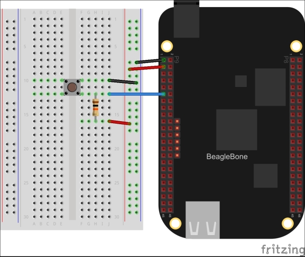
A tactile switch is a type of momentary push button, meaning that it is only engaged while it is held down and returns to its default state when released. They are widely available from stores such as Adafruit and SparkFun, and it is also one of the more breadboard-friendly types of switches. Depending on the variety of tactile switch, it might require straightening the pins with a pair of pliers to get it to lock into your breadboard. Wire the switch to GPIO0_30 (P9.11), as shown in the figure:
Now run the following code and press the button; you should see a value of 0 normally and 1 when you press the button:
from bbio import *

SW_PIN = GPIO0_30

def setup():
  pinMode(SW_PIN, INPUT)

def loop():
  print "switch state:", digitalRead(SW_PIN)
  delay(250)

run(setup, loop)
To do the same in Adafruit_BBIO, we'll first need to configure the pin as an input, as shown in the following code:
# config-pin P9_11 in
Note
Remember, you'll need to first load the universal cape overlay as described in Chapter 3, Digital Outputs, before using a config-pin.
You can then use GPIO.input() to read the pin state:
from Adafruit_BBIO import GPIO
import time

GPIO.setup("P9_11", GPIO.IN)

while True:
print "switch state:", GPIO.input("P9_11")
time.sleep(0.25)So what's the resistor in the preceding circuit for? Let's think about what would happen without the resistor. When you press the button, the two sets of pins are shorted together, and therefore, the GPIO input is connected to ground. The 0 V ground level is read by the GPIO module as a logical low, and 0 is returned. When the button is not pressed, the two sets of pins are disconnected from each other, leaving the GPIO input disconnected, or floating. In this floating state, external electric fields can induce voltages on the GPIO input, especially with the external wire connecting it to the switch acting as an antenna. These induced voltages might or might not cross the GPIO module's low-high threshold. So leaving a GPIO input in a floating state will result in unpredictable readings.
We can easily avoid leaving the GPIO input floating when connecting a switch by adding a single resistor. In the preceding circuit, when the button is pressed the GPIO input is still connected directly to ground, and therefore the voltage is still 0 and a low value is read. When not pressed, the GPIO input is connected to 3.3 V, and since the input has much higher impedance than the 10 kΩ of the resistor, the voltage on the input is 3.3 V and high value is read. This is called a pull-up resistor, because this is pulling the input up to 3.3 V. The circuit can also be reversed, where the switch connects the input to 3.3 V and the resistor pulls it down to 0 V when not pressed, in which case it is called a pull-down resistor.
Note
The value of the pull resistor is not crucial, but you typically want something in the range of 1 kΩ-100 kΩ. If the value is very low, then there can be a large amount of current flowing through it when the switch is engaged. If the value is very high, it can create a voltage divider with the input impedance of the GPIO module when the switch is not engaged, potentially dividing the voltage down below the LOW-HIGH threshold. 10 kΩ is a good choice for most applications.
The GPIO modules in the BeagleBone's processor also include configurable pull-up and pull-down resistors, and PyBBIO allows you to use them in place of external resistors. First, wire up the tactile switch without any pull resistor.
For this circuit, you will need:
- Breadboard
- 1x tactile switches
- Jumper wires
The connection is shown in the following figure:
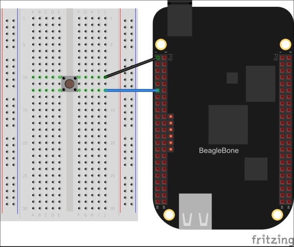
Then we just need to enable the internal pull-up resistor when we call the pinMode() function, as shown in the following code:
from bbio import *

SW_PIN = GPIO0_30

def setup():
    pinMode(SW_PIN, INPUT, PULLUP)

def loop():
    print "switch state:", digitalRead(SW_PIN)
    delay(250)

run(setup, loop)
To use the internal pull-down resistor, you can use the PULLDOWN keyword instead.
The pull-up and pull-down resistors are part of the pin multiplexing subsystem, and therefore, must be set through the device tree. PyBBIO does this with its custom overlays, but if you're using Adafruit_BBIO, you can still enable pull-up and pull-down resistors with config-pin. To enable a pull-up resistor, append a plus sign to the in option, as shown in the following code:
# config-pin P9_11 in+
Append a minus sign for a pull-down resistor:
# config-pin P9_11 in-
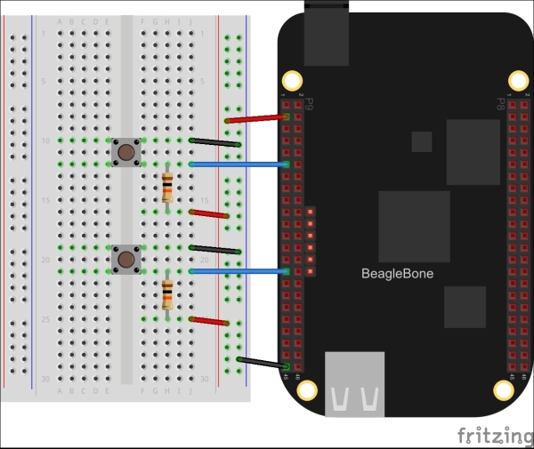
One technique for reading buttons is called polling, where a program repeatedly reads the input state fast enough to catch button presses. Let's take a look at an example of this. First, wire up two tactile switches, this time to GPIO0_30 (P9.11) and GPIO3_15 (P9.29).
For this circuit, you will need:
- Breadboard
- 2x tactile switches
- 2x 10 kΩ resistors
- Jumper wires
Place the buttons on your breadboard, as shown in the diagram:
Try out the following program as an example:
from bbio import *

UP_SW = GPIO0_30
DOWN_SW = GPIO3_15

set_value = 50
min_value = 0
max_value = 100

def setup():
    pinMode(UP_SW, INPUT)
    pinMode(DOWN_SW, INPUT)

def loop():
    global set_value
    if (not digitalRead(UP_SW) and set_value < max_value):
        set_value += 1
        print "value set to {:d}".format(set_value)
    if (not digitalRead(DOWN_SW) and set_value > min_value):
        set_value -= 1
        print "value set to {:d}".format(set_value)
    delay(100)

run(setup, loop)
When you run it, you should see it responding to your button presses by incrementing and decrementing the global set_value variable. Set a delay of 100 in the loop() function; because the program is continually reading the button states each time through the loop, the delay helps to prevent it from registering many button presses at once (don't take my word for it, try running the program without it). That delay can become a problem when you start doing other tasks in your program, as it eats up processing time. So let's look at a couple other ways to handle this.
The first technique is to ignore each button for a set amount of time after the first push is detected, as shown in the following code:
from bbio import *

UP_SW   = GPIO0_30
DOWN_SW = GPIO3_15

DEBOUNCE_MS = 250
last_up_press = -DEBOUNCE_MS
last_down_press = -DEBOUNCE_MS

set_value = 50
min_value = 0
max_value = 100

def setup():
    pinMode(UP_SW, INPUT)
    pinMode(DOWN_SW, INPUT)

def loop():
    global set_value, last_up_press, last_down_press
    now = millis()
    if (not digitalRead(UP_SW) and set_value < max_value):
        if (now - last_up_press >= DEBOUNCE_MS):
          set_value += 1
          print "value set to {:d}".format(set_value)
          last_up_press = now
    if (not digitalRead(DOWN_SW) and set_value > min_value):
        if (now - last_down_press >= DEBOUNCE_MS):
            set_value -= 1
            print "value set to {:d}".format(set_value)
            last_down_press = now
    delay(10)

run(setup, loop)
So, in this case, we're using the PyBBIO's millis() function, which returns the number of milliseconds that have elapsed since the program started running, to compare each LOW GPIO reading to the time of the last registered button press for that input. The LOW level is only registered as a button press if at least the configured number of milliseconds have passed.
Note
We've used the variable name DEBOUNCE_MS because this is equivalent to a simple button debouncing. When a button is pressed, the metal contacts inside it tend to bounce off each other a few times before making solid contact, and debouncing is used to prevent this from causing multiple button press events. Python running in GNU/Linux on the BeagleBone doesn't run fast enough to pick up button bounce, but this is still the same technique nonetheless.
Another strategy is to completely ignore a pressed button until it has been released. Let's take a look at the following code:
from bbio import *

UP_SW   = GPIO0_30
DOWN_SW = GPIO3_15

up_pressed = False
down_pressed = False

set_value = 50
min_value = 0
max_value = 100

def setup():
    pinMode(UP_SW, INPUT)
    pinMode(DOWN_SW, INPUT)

def loop():
    global set_value, up_pressed, down_pressed
    now = millis()
    if (not digitalRead(UP_SW) and set_value < max_value):
        if (not up_pressed):
          set_value += 1
          print "value set to {}".format(set_value)
          up_pressed = True
    else: up_pressed = False
    if not (digitalRead(DOWN_SW) and set_value > min_value):
        if (not down_pressed):
            set_value -= 1
            print "value set to {}".format(set_value)
            down_pressed = True
    else: down_pressed = False
    delay(10)

run(setup, loop)
What's nice about this technique is that you can repeatedly press the buttons as fast as you'd like without having the forced delay between presses. Of course, there are plenty of other techniques of cleaning up button presses, including different combinations of the ones here.
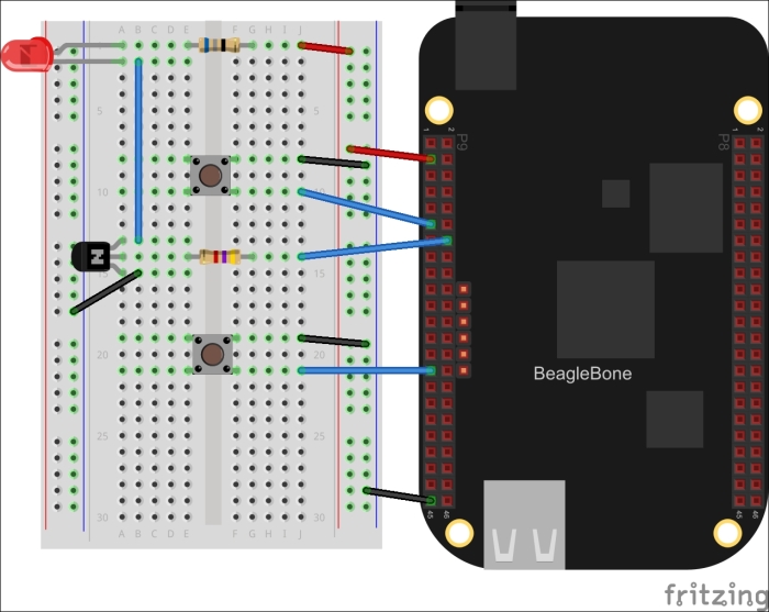
Before we continue, let's take the example we've been working on one step further, and actually make it do something. Start by adding the NPN LED driving circuit we looked at in Chapter 3, Digital Outputs, to PWM1A (P9.16). The external pull-up resistors have been removed here to make more space on the breadboard.
For this circuit, you will need:
- Breadboard
- 2x tactile switches
- 1x 5 mm LED
- 1x 4.7 kΩ resistor
- 1x 68 Ω resistor
- 1x 2N3904 NPN transistor
- Jumper wires
Wire the buttons on your breadboard, as shown in the figure:
With just a few additions, we can make the two-button-example control the brightness of the LED, as shown in the following code:
from bbio import *

UP_SW   = GPIO0_30
DOWN_SW = GPIO3_15
LED     = PWM1A

DEBOUNCE_MS = 250
last_up_press = -DEBOUNCE_MS
last_down_press = -DEBOUNCE_MS

set_value = 50
min_value = 0
max_value = 100
increment = 5

def setup():
    pinMode(UP_SW, INPUT, PULLUP)
    pinMode(DOWN_SW, INPUT, PULLUP)
    analogWrite(LED, set_value, 100)

def loop():
    global set_value, last_up_press, last_down_press
    now = millis()
    value_changed = False
    if (not digitalRead(UP_SW) and
        set_value <= max_value-increment):
        if (now - last_up_press >= DEBOUNCE_MS):
            set_value += increment
            print "value set to {:%i}".format( % set_value)
            last_up_press = now
            value_changed = True
    if (not digitalRead(DOWN_SW) and
        set_value >= min_value+increment):
        if (now - last_down_press >= DEBOUNCE_MS):
            set_value -= increment
            print "value set to {:i}".format(set_value)
            last_down_press = now
            value_changed = True

    if (value_changed): analogWrite(LED, set_value, 100)
    delay(10)

run(setup, loop)
One of the additions is the global increment variable, which lets you set the amount each button press changes the duty cycle by; that way you don't have to press it a hundred times to go from a 0 to 100 percent duty cycle. Also added is the value_changed variable, which ensures that the PWM module is only being reconfigured when a change has been requested by way of a button press. Without this, the value would always be set every 10 ms; and each time it is set, there is a slight interruption in the PWM output while the new value is taking effect, which would cause a noticeable flicker on the LED.
Polling buttons can be troublesome when your program has to do other work at the same time. One alternative is to use what's called interrupts. Like most modern microcontrollers and microprocessors, the BeagleBone's processor supports GPIO input interrupts. They can trigger the processor to jump to a particular location in its program memory when it detects a certain state on a GPIO input. The supported states are typically rising and falling edges (that is, the transitions between logic levels), and low or high levels themselves. The Linux kernel on the BeagleBone is able to receive these interrupt signals and generate a change to a special file if configured to do so. A user space process (as opposed to a kernel space process, like a kernel driver) can then monitor the said file, and can call a locally defined callback function when it detects a change. That might sound a bit complicated, but it's pretty straightforward to use interrupts in PyBBIO, especially if you've written any event-driven code before. Let's take a look at what the LED brightness control program might look like using interrupts instead of polling, as shown in the following code:
from bbio import *

UP_SW   = GPIO0_30
DOWN_SW = GPIO3_15
LED     = PWM1A

DEBOUNCE_MS = 250
last_up_press = -DEBOUNCE_MS
last_down_press = -DEBOUNCE_MS
value_changed = False

set_value = 50
min_value = 0
max_value = 100
increment = 5

def upHandler():
    global set_value, last_up_press, value_changed
    now = millis()
    if (now - last_up_press < DEBOUNCE_MS): return
    if (set_value <= max_value-increment):
        set_value += increment
        print "value set to {:i}".format(set_value)
        last_up_press = now
        value_changed = True

def downHandler():
    global set_value, last_down_press, value_changed
    now = millis()
    if (now - last_down_press < DEBOUNCE_MS): return
    if (set_value >= min_value+increment):
        set_value -= increment
        print "value set to {:i}".format(set_value)
        last_down_press = now
        value_changed = True

def setup():
    pinMode(UP_SW, INPUT, PULLUP)
    pinMode(DOWN_SW, INPUT, PULLUP)
    attachInterrupt(UP_SW, upHandler, FALLING)
    attachInterrupt(DOWN_SW, downHandler, FALLING)
    analogWrite(LED, set_value, 100)

def loop():
    global value_changed
    if (value_changed):
        analogWrite(LED, set_value, 100)
        value_changed = False
    delay(10)

run(setup, loop)
Notice how the main loop is completely free to do any additional work that might be required by your program.
Adafruit_BBIO doesn't implement interrupt callback functions like PyBBIO does, but it does have two options to receive interrupt signals. The first is the blocking wait_for_edge() function, which blocks the program until the specified edge is detected. For example, we could wait for a button press on GPIO0_30 (the preceding circuit will work). Let's take a look at the following code:
from Adafruit_BBIO import GPIO

button = "P9_11"
GPIO.setup(button, GPIO.IN)
GPIO.wait_for_edge(button, GPIO.FALLING)
print "Button pressed!"
The other option is to tell Adafruit_BBIO to detect a particular edge in the background, then routinely ask it if it has been detected. Let's take a look at the following code:
from Adafruit_BBIO import GPIO
import time

button = "P9_11"
GPIO.setup(button, GPIO.IN)
GPIO.add_event_detect(button, GPIO.FALLING)

while True:
    if GPIO.event_detected(button):
        print "Button pressed!"
    time.sleep(1)
This won't necessarily allow you to respond to interrupts as quickly as possible, but it will at least guarantee that your program won't miss any input signals while it's taking care of other tasks.
In both cases, you'll want to first enable the pull-up resistor, as shown in the following code:
# config-pin P9_11 in+