
A UART is one of the most common serial communication subsystems. To transmit data with a UART, one or more bytes are written to an internal shift register by a CPU from where they are then serially sent out; a single output is sent out at a previously defined clock rate. Another UART (programmed to run at the same clock rate as the first), with its single input connected to the output of the first, detects the start of this bit stream, and it sequentially reads the bits into its own internal shift register. Once all the bits are sent, the receiving UART signals its CPU to let it know there's data ready, and the CPU then reads it out of the receive register.
A UARTs transmit output is referred to as TX, and its received input as RX. They often have some additional signals for more advanced handshaking, called flow control, which help ensure synchronization. We'll only cover the RX and TX signals here, as we won't be using the flow control signals in any of the demos in this book. Synchronization between two UARTs is typically achieved without the additional flow control signals by prepending one or more start bits to each byte to mark its start, and sometimes one or more stop bits are appended to each byte to mark its end. Two UARTs are connected together by wiring the TX signal from one to the RX input of the other, and vice versa.
Communication between two UARTs completely relies on them running at the same speed, as they must agree on how much time the digital state is held for each bit. The measurement of speed used for UARTs is the baud rate, or symbols per second, where a symbol refers to what encodes a single bit. In more advanced communication protocols, there can be more than one pulse per bit to provide error immunity, but in a standard UART communication there is one pulse per bit, so the baud rate is equivalent to the rate in bits per second.
There are a number of standard baud rates used: 110, 300, 600, 1200, 2400, 4800, 9600, 14400, 19200, 28800, 38400, 56000, 57600, and 115200 symbols/second. Many modern UARTs also support the higher standard rates of 128000, 153600, 230400, 256000, 460800, and 921600 symbols/second. Some UARTs can autodetect the baud rate of a device connected to it, but typically both endpoints will have been programmed ahead of time to use the same baud.
The BeagleBone's processor contains six separate UART modules, labeled UART0 - UART5. UART0 is reserved for a serial console, as described in Chapter 2, Getting Started, and UART3 is not fully exposed on the expansion headers. That leaves UART1, UART2, UART4, and UART5 open for general use. These use the following pins on the expansion headers:
- UART1:
- RX - P9.26
- TX - P9.24
- UART2:
- RX - P9.22
- TX - P9.21
- UART4:
- RX - P9.11
- TX - P9.13
- UART5:
- RX - P8.38
- TX - P8.37
Note
The UART5 RX and TX signals are shared with pins used by the HDMI driver, so to use it HDMI must first be disabled. See Appendix A, The BeagleBone Black Pinout.
Each UART on the BeagleBone is enabled separately. As with the other subsystems, PyBBIO automatically loads the overlays to enable each UART when you initialize it. Otherwise, you'll have to enable them manually with capemgr by loading the overlays named BB-UART1, BB-UART2, BB-UART4, and BB-UART5. When the overlay is loaded, a device node will be created, which is a special kernel driver interface file in /dev/ directory. The BeagleBone's kernel calls these device nodes /dev/ttyOx, where x is the UART number. So enabling UART2 with the BB-UART2 overlay will create the device node at /dev/ttyO2 (note that's the letter O following tty, not the number 0). Inside the operating system abstraction, these particular virtual devices are referred to as serial ports. The serial port kernel driver allows you to control a UART by writing to and reading from its device node as if it were a regular file, with some initial setup with ioctl to configure parameters like the baud rate.
Note
ioctl is a system call on Unix-like systems that takes three arguments:
- A file descriptor of an open special file, such as a device node for a serial port
- A request code (specific to the device driver in question) describing what parameter you want to read or manipulate
- An address in memory where a read parameter will be placed, or where a value is stored if you're making a change
ioctl is used to read and manipulate parameters that don't fit into the standard file read/write model, such as settings like baud rates
In PyBBIO, there is a preinstantiated object for each UART, named Serial1, Serial2, Serial4, and Serial5 respectively. The full API docs can be found on the PyBBIO wiki page at https://github.com/graycatlabs/PyBBIO/wiki/serial. As an example, here's a simple program that listens for incoming data on UART2, receives it, and then transmits it back out from UART2:
from bbio import *
def setup():
# Start Serial2 at 9600 baud:
Serial2.begin(9600)
def loop():
if (Serial2.available()):
# There's incoming data
data = ""
while(Serial2.available()):
# If multiple characters are being sent we want
# to catch them all, so add received byte to our
# data string and delay a little to give the
# next byte time to arrive:
data += Serial2.read()
delay(5)
# Print what was sent:
print "Data received:
'%s'" % data
# And echo it back to the serial port:
Serial2.write(data)
delay(100)
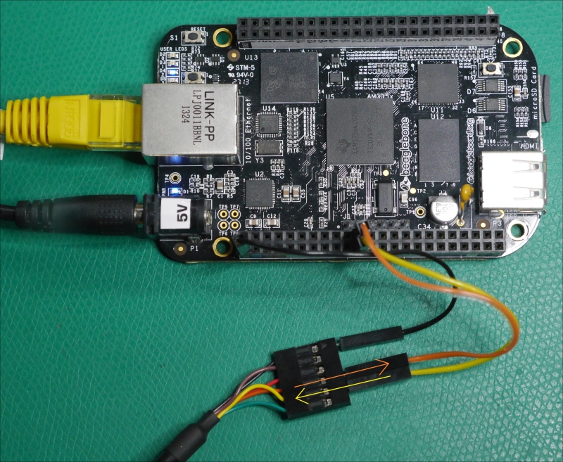
run(setup, loop)You can test this program with the USB to serial converter from Adafruit (http://www.adafruit.com/products/70) mentioned in Chapter 2, Getting Started; hook up the black ground wire to a GND pin (like P9.1), the orange TX wire to the UART2 RX pin (P9.22), and the yellow RX wire to the UART2 TX pin (P9.21), as shown (where the arrows indicate the direction of data flow):
You'll need to first install the driver for the USB to the serial converter inside the cable, which you can find at http://www.ftdichip.com/Drivers/VCP.htm. With the driver installed, when you plug the serial cable into a Windows PC, it should detect it and assign it a COM port number. If you're not sure what number it was assigned, you can check for a USB Serial Port(COM15) entry in Device Manager:
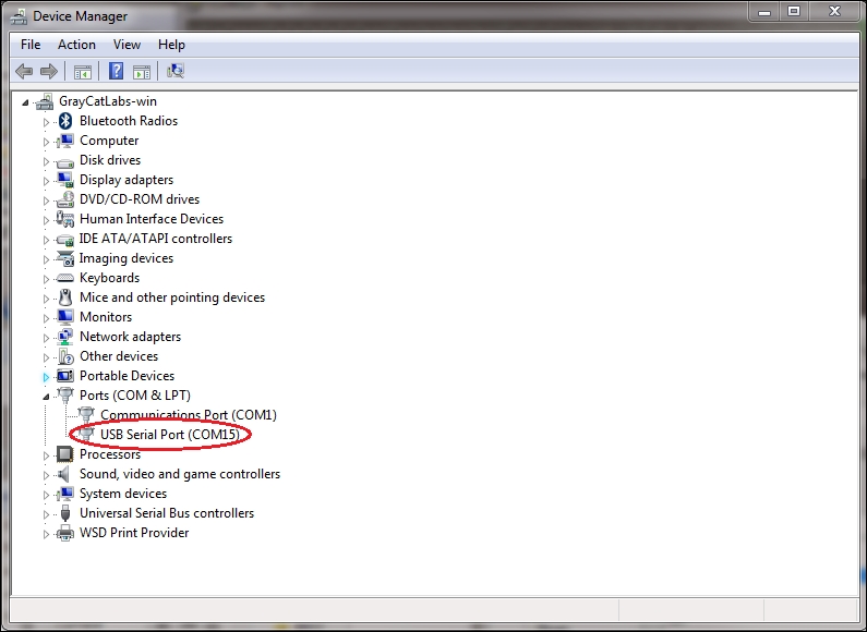
In the screenshot, you can see it was assigned COM15. Now open PuTTY (which we used previously in Chapter 2, Getting Started), select Serial line and enter the COM port and baud rate:
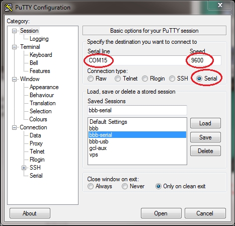
We've used the 9600 baud rate here, since that's what we're using in the example program; any standard baud rate will work as long as they're both the same.
Get the example program running on your BeagleBone Black and then press Open in PuTTY. You'll be dropped into a terminal window where you can type characters on your keyboard, which are sent to the converter IC in the USB cable, sent out to the ICs UART over the cable, and received in the BeagleBone Black's UART2. The characters are read by the Python program, printed to the terminal where it's running, then they are sent back through the serial cable to your PC where they are received and displayed on the PuTTY terminal. We can see this happening with an oscilloscope:
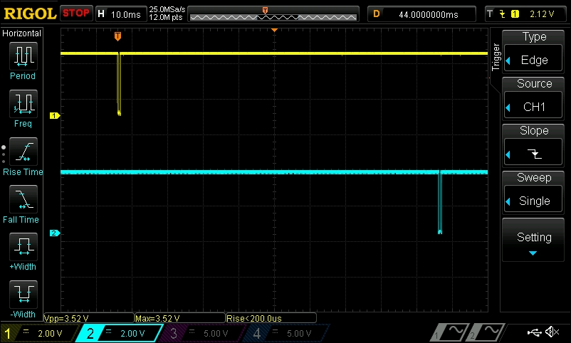
In the oscilloscope screenshot, the yellow trace shows voltage from a probe connected to the PC's TX signal going to the BeagleBone's RX pin, and the blue trace shows the signal from the BeagleBone's TX pin being sent to the PC. We can see that there is data being sent from the PC to the BeagleBone, then a short time later, there is data being sent back to the PC. Let's zoom in a little closer on the first chunk of data:
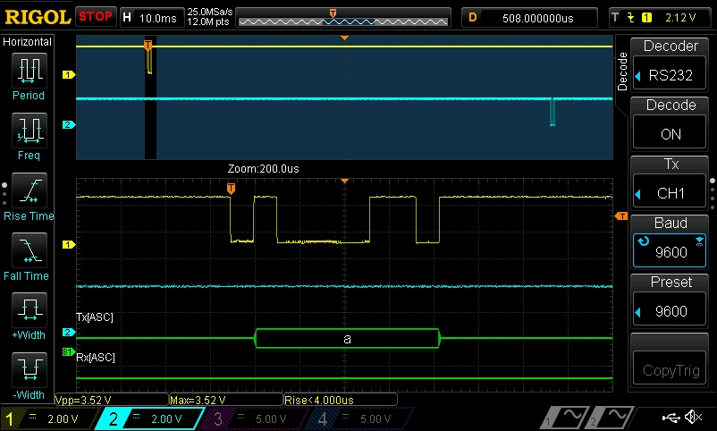
Here, you can see that the serial decode feature has been enabled on the oscilloscope, and it shows us that the data sent is the ASCII character "a". In ASCII, the letter "a" is encoded as 0x61, or in binary, 01100001.
Note
You might also notice that the decoder selected on the oscilloscope screenshot is called RS232. RS232 is a serial transmission standard. PCs used to always include serial ports to connect peripheral devices such as modems and printers, and is still widely used in commercial and industrial applications. While the voltage levels we're using here are different from RS232, standard UARTs still use the same basic serializing protocol.
Let's take a closer look at the byte we recorded to make sure we agree with the decoder:
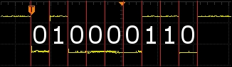
We just said that the binary value of the ASCII character "a" is 01100001, but what actually got sent was 010000110, so what's going on here? The first thing to note is that this is in fact 9 bits, which is one bit longer than a standard 8-bit byte. The reason for this is that the first bit sent is actually a start bit, which tells the receiving UART that a byte is on the way. So that leaves 10000110, which is the binary value of a in reverse. That's because the data is being serialized in the Least Significant Bit First (LSB) order, where the byte is transmitted right-to-left, as opposed to Most Significant Bit First (MSB), where the byte would be transmitted left-to-right; this is the standard bit ordering used by UARTs.
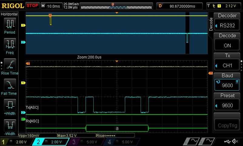
And if we zoom in to the byte that the BeagleBone sends back, we can see that it is also the ASCII character a:
Adafruit_BBIO doesn't include its own objects for controlling the serial ports, but the pySerial Python library, which PyBBIO's serial port class is built on top, can be used directly in an Adafruit_BBIO program. The pySerial API can be found at http://pyserial.sourceforge.net/pyserial_api.html. The equivalent echo program using pySerial would look like this:
import serial, time

port = serial.Serial("/dev/ttyO2", 9600)

while True:
    if (port.inWaiting()):
        data = ""
        while(port.inWaiting()):
            data += port.read()
            time.sleep(0.005)
        # Print what was sent:
        print "Data received:
 '%s'" % data
        port.write(data)
    time.sleep(0.1)
Remember, if you're not using PyBBIO, you'll need to manually load the Device Tree overlay to enable the UART, for example:
# echo BB-UART2 > /sys/devices/bone_capemgr.*/slots