
Printed polymer solar cells
Abstract:
This chapter describes the constitution of the polymer solar cell with general focus on upscaling, large-scale industrial manufacture and demonstration of the technology. Initially, the classical device architecture and function of the polymer solar cell are described and the upscaling to large area production, with aims and limitations, is discussed. Secondly, a brief overview of different printing and coating techniques, relevant to the manufacturing of polymer solar cells, is given with examples of some of the best-described routes to ‘all printed and coated’ industrially manufactured polymer solar cells. Finally, small- and large-volume polymer solar cell applications are evaluated together with the potential market areas. Also recent demonstrations of the polymer solar cell technology are shown, which serves the purpose of honing our understanding of the capacity and maturity of the technology.
19.1 Introduction
In this chapter, the history of polymer solar cells and an overview of the research field are given briefly, with due reference to the most recent reviews [1–5] and books [6–9] on the topic that have been extensively reviewed.
19.1.1 The polymer solar cell
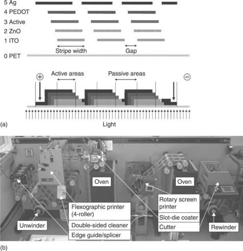
The simplest form of a polymer solar cell is shown in Fig. 19.1. The illustration is simplified and focus is on the active layer, which is classically a mixture of the conjugated polymer poly-3-hexylthiophene (P3HT) and [6,6]-phenyl-C61-butyric acid methyl ester (PCBM) that comprise the active layer, responsible for light absorption, carrier generation and transport to two electrodes where at least one of the electrodes is transparent to light. When light is absorbed in the polymer material (donor), an electron is excited from the HOMO into the LUMO, which leads to a bound state (exciton) of an electron and an imaginary particle called an electron hole. Subsequently, the generated excitons need to diffuse to the polymer–fullerene interface in order to undergo photoinduced charge transfer. Generally, the exciton diffusion length is restricted to 5–20 nm in organic materials so the formation of a polymer–fullerene nanoscale interpenetrating bicontinous network within the active layer is essential to guarantee that every generated exciton can reach the polymer–fullerene interface. From the excited state of the polymer, an electron can be transferred into the LUMO of the fullerene acceptor if the energy levels are properly aligned (Fig. 19.2), resulting in free charge carriers that finally are transported to the electrodes, creating a photovoltaic effect.
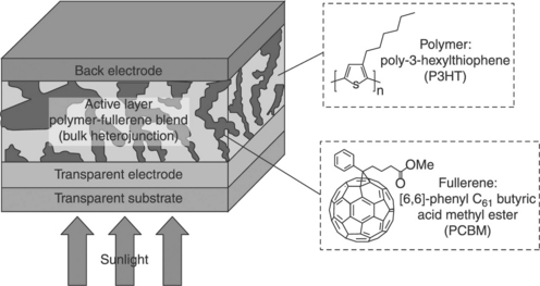
19.1 A view of a simple bulk heterojunction polymer solar cell comprising a single active layer and two electrodes.
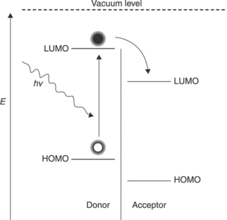
19.2 Energy-level diagram of two semiconductor materials. Upon light absorption in the donor material, an electron is excited from the HOMO to the LUMO followed by photoinduced charge transfer to the LUMO of the acceptor, resulting in free charge carriers.
In practical terms, the polymer solar cell also includes some extra layers to enable processing and performance. The typical geometry (or layer structure) employed in laboratory studies is mostly a result of the historical development of the technology. The research on polymer solar cells has been obsessively focused on the active layer and the disposition of the other layers has been chosen dogmatically for reasons of availability, performance and practicality. This implies that the remaining layers and procedures have not developed and, as a consequence thereof, the evolution of the laboratory cell into a commercially viable technology is somewhat slower than anticipated by many at the turn of the millennium, when the commercialization of the polymer solar cell was deemed to be imminent. As it stands today, there is still a considerable distance to cover before polymer solar cells have a chance of competing with inorganic thin-film solar cells in terms of cost, stability and performance.
The polymer solar cell, however, has a few aces up its sleeve that make it the only other viable PV technology on a huge scale. Only silicon PV exhibit limitless materials availability, whereas all other inorganic and thin-film technologies employ elements with low natural abundance or toxicity that cannot be handled in a foreseeable manner. Unlike the inorganics (i.e. Si, CdTe, CIGS), polymer solar cell devices can be solution processed under ambient conditions and do not depend on the large built-in electric field of a PN junction in order to separate the created electrons and holes when light is absorbed in the active layer. Also, in terms of material properties conjugated, polymers can easily be modified by adapting their chemical structure, through organic synthetic techniques, resulting in greater customization compared to the inorganics. Other organic thin-film solar cells based on low-cost materials that do not rely on expensive vacuum processing are the dye-sensitized solar cells (DSSCs). However, their major weakness is that they require a built-in liquid conductor (electrolyte solution), which has significant stability problems associated with temperature. Provided that the challenges of polymer solar cells can be overcome, polymer solar cells will become the prevailing PV technology in the future and also a major source of electrical energy. A balanced view of the market potential and patent landscape for polymer solar cells has been published recently [2].
19.1.2 The typical device geometry – the history of making polymer solar cells
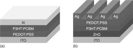
Aside from the active layer, which is central to device function, the polymer solar cell has two electrodes and most often also some charge selective layers. The typical polymer solar cell should thus be considered as a five-layer device. In the laboratory setting, a glass substrate with a transparent electrode of indium–tin oxide is typically employed. One of the first developments was the inclusion of a semitransparent hole transporting and hole selective interlayer of PEDOT:PSS poly (3,4-ethylenedioxythiophene)-poly(styrenesulfonate), which also smoothed the indium–tin oxide surface. This enabled easier processing of defect-free active layers. Later, electron-selective layers were employed between the active layer and the electrode (i.e. LiF, MgF2).
For the first 20 years of the development of polymer solar cells most of the layers were vacuum processed, while the technology has been marketed and described as a solution-based technology that enables printing of the layers. In the standard cell described above, only PEDOT:PSS and the active layer are solution-processed, whereas ITO, LiF and the back electrode are vacuum-processed. It is clear that this has some bearing on the transfer of the technology to an all-printable setting, as multilayer solution processing only works if the previously deposited layers are not soluble in the solvents employed in the subsequently processed layers. In the case of PEDOT:PSS and typical active layer solutions, this has been fortuitous because PEDOT:PSS is traditionally processed from an aqueous solution and gives a high-energy surface that is easily wetable by low-surface-tension solutions of fullerenes and conjugated polymers in common organic solvents such as toluene, xylenes, chlorobenzene and 1,2-dichlorobenzene. The inverted solar cell geometry (also shown in Fig. 19.3) easily allows for solution processing since the holes are extracted at the back electrode, enabling use of more noble metals that can be printed, such as silver.
19.1.3 Visions for making polymer solar cells on a large scale – the need for ambient processing on flexible substrates
The standard rigid glass laboratory device falls somewhat short of enabling fulfillment of the vision of large-scale, low-cost, high-speed manufacture of polymer solar cells – especially since the capital investment in equipment based on vacuum and inert atmosphere processes is enormous compared to the common understanding of production environments based on commonly known printing and coating techniques [5]. One of the promising aspects of the polymer solar cell technology is that it should enable processing under ambient conditions at low temperature on flexible plastic substrates, and this is what has driven the research of polymer solar cells for many years. The flexibility is a requirement for manufacturing at high speed and the use of simple polymer materials such as polyesters as substrates is quite possibly a requirement for achieving a low cost. The vision of low-cost, light-weight, high-performance polymer solar cells is thus likely to be reached only if all the processing can be done using simple equipment on common substrates using common coating and printing techniques. So far, however, development has not really been in this direction, and the challenges of taking the laboratory result, which typically comprises a glass substrate, evaporated electrodes and a very small area, have been grossly underestimated. In principle, a whole new knowledge platform is needed to manufacture polymer solar cells using R2R techniques under ambient conditions. Most of this knowledge is not pre-existing and the belief that the printing and coating industry can simply apply their knowledge to directly manufacturing polymer solar cells is naive. The basis for this observation is that the existing coating and printing industry is not used to the requirement that the printed or coated material needs to have an additional function after printing/coating and drying. Most often this line of business has fulfilled its goals when registry is kept and printing/coating is readable or of a particular optical appearance. To make the vision of polymer solar cells a reality much new knowledge must be built that rests on the existing state-of-the-art.
19.2 Printing and coating methods
Printing and coating techniques can be divided into a few rough groups that define their usability in the context of polymer solar cells [5]. These groups are the dimensionality of the printing, ink transfer and achievable wet layer thickness. As nearly all printing and coating in reality deals with the wet film, this is really where focus should be (the dry film is obtained in the drying process, which is a different and equally challenging matter).
19.2.1 Available printing techniques
Many techniques are available for the transfer of an ink material onto a surface and they are often termed as printing or coating techniques. The term ‘coating’ is normally employed to describe an ink transfer that is uniform (i.e. without pattern) and often implies that there is no physical contact between the surface that receives the ink and the system that supplies it. The term ‘printing’ is normally employed when dealing with a technique that supplies the ink to the surface in a two-dimensional pattern. The process is traditionally through a reversing action where in the simplest form the ink is transferred to a stamp with the desired pattern. The stamp or stencil is then brought into contact with the receiving surface whereby the ink is transferred. In the modern form, the stamp has been replaced with a cylinder.
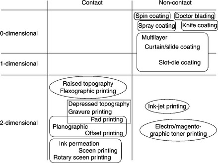
There are naturally exceptions to these general rules that are mostly historic, i.e. brush painting and ink-jet printing. All the printing techniques that have been developed had a particular purpose at that time that was rooted in either the printing or coating job at hand or in the need to coat or print a particular ink, i.e. a cheap office printer with fine resolution, and very large and even surface coating. In some cases, the development has been ink-driven and in other cases driven by the application technique. Some of the available printing and coating techniques have been summarized in Fig. 19.4, where they have been categorized according to their dimensionality and transfer type.
19.2.2 The suitability of different printing techniques
When considering printing and coating techniques in the context of polymer solar cells, it is clear that it is almost exclusively ink-driven and the success of one single coating technique has dominated the field of polymer solar cells and possibly also hindered its development. Spincoating is an excellent technique for the laboratory and combines simplicity in use with reproducibility, low ink usage (but large ink waste) and a very good control of the thickness and evenness of the coated film. In the printing and coating industry it is customary to use additives to an ink to alter viscosity, wetting, binding, rheology, etc. In the case of inks for polymer solar cells, this is as a general rule not possible or at least much more difficult and in the current state-of-the-art the development is ink-driven, i.e. the printing or coating technique has to match the ink properties. An additional limitation to the development is the cost of the technique. Some printing and coating methods can be adjusted to the printing needs, i.e. pattern, area, speed, at very little or no cost. The change of a screen-printing mask is, for instance, low in cost and ink-jet printing that has digital master has zero cost associated with changing the printed pattern. Gravure printing employs a very costly engraved roller and thus represents the opposite case. In terms of development, it is clear that the pursuit of an expensive technique is warranted only if it is the sole available technique. This does not mean that the expensive technique is not useful or might not be superior, it just means that if there are other available techniques they are likely to be employed instead, even with the disadvantages they might include. In the case of a typical five-layer inverted polymer solar cell, as illustrated in Fig. 19.3b, it is clear that the five different layers might require five different coating or printing techniques as each layer has different requirements. The printed back electrode, for instance, must be highly conducting and therefore it is reasonable to use a printing technique that gives rise to a thick deposit to enable high conductivity. Conversely, the active layer must be relatively thin, but must also present a large degree of evenness. While it is possible to employ the same printing or coating technique for both layers (or all layers), it is most likely that several different printing and coating techniques will be employed that match the different requirements best.
19.2.3 The different layers and the printing methods of choice
As examples, some of the best-described routes to an ‘all printed and coated’ polymer solar cell can be compared. The first example and first public demonstration of industrially manufactured polymer solar cells described the preparation of a five-layer inverted polymer solar cell where all layers were prepared by screen printing [10]. The solar cells were applied in a ‘solar hat’. The inks for the electron transfer layer and the active layer were specifically redesigned so that they were screen printable. This required the development of a particular viscous solvent that allowed for the screen printing of thin zinc oxide and active layers. The work showed that it was possible, but also that the devices were of low overall performance limited by the manufacturing technique. The second example, termed ProcessOne [11], makes use of screen printing for processing the two electrodes. The ITO front electrode was patterned through printing an etch resist and etching of the ITO. The metallic back electrode was screen-printed silver. The three middle layers, comprising zinc oxide as the electron transport layer, P3HT-PCBM blend as the active layer and PEDOT:PSS as the hole-transport layer, were all coated into stripes using slot-die coating. It is not currently clear what printing and coating techniques will win the race in the end, but it is likely that the typically industrially manufactured polymer solar cell will employ both screen printing and slot-die coating. This combination of techniques has been shown several times [12–15].
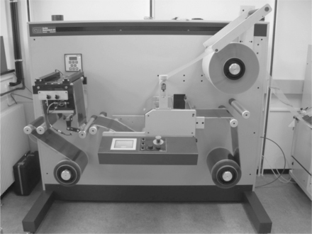
19.3 Manufacturing methods for complete polymer solar cells
In addition to the printing and coating techniques that must be mastered before one can manufacture polymer solar cells, several other fields of expertise within substrate materials, adhesives, foil handling, electrical connections, automated characterization techniques, etc. must be encompassed.
19.3.1 Substrates
The substrate is a very important part of the polymer solar cell and while many different substrates can be envisaged there are in reality only a few that have industrial relevance, due to issues of both cost and performance. The performance is meant to include aspects of optical quality and thermal stability (chemistry and shape). There are substrates that may present certain advantages such as exceptional thermal stability (i.e. Kapton) [15] or biodegradability (i.e. PLA) [16] but that are not suitable for state of the art polymer solar cell processing due to cost (Kapton) or poor temperature/solvent stability (PLA). PET is one polymer material that has a low cost and superior chemical, optical and thermal stability, and for many reasons this material is believed to be the best candidate for polymer solar cells, both for substrates and barrier foil.
19.3.2 Multilayer processing and contacting
The typical polymer solar cell comprises a multilayer structure with typically three to five or more coated and printed layers. This naturally implies that the overall process allows for printing and coating subsequent layers on top of already processed layers. With two layers this is relatively easy to achieve as one prepares the first layer from an aqueous solution and the subsequent layers from an organic solvent. The solvent orthogonality in this way solves problems of the solvents in the second layer dissolving the previously deposited layer. Incidentally, this is just the case for traditional laboratory devices that employ an already deposited (and insoluble) ITO layer whereupon PEDOT:PSS is normally spin-coated from an aqueous dispersion. The active layer is normally deposited on top of the PEDOT:PSS layer that presents a large surface energy, followed by evaporation of a metal back electrode. In many ways this is fortuitous and most laboratory workers are thus not fully aware of the extraordinarily large challenge associated with going to full solution processing on three or more layers. In order to achieve this successfully one must have the ability to switch off the solubility of previously processed layers such that the same or similar solvents can be used for the entire processing chain. In the case of the solar hat [10], this was achieved using a combination of cross-linking of inorganic layers and thermocleavage of the active layer, and in the case of ProcessOne [11], this was achieved by employing cross-linking of zinc oxide nanoparticles, followed by a soluble active layer, a very thick PEDOT:PSS layer and finally a printed silver electrode. In addition to being able to print and coat multilayer structures, it is also very useful (or a requirement) that one is able to pattern some or all of the layers, such that many cells can be printed and coated and electrically interconnected.
The latter point is due to the often significant sheet resistive losses associated with making large area polymer solar cells. The solution to this problem is the well known series connection of many smaller devices. This has been illustrated in Fig. 19.5, where it is shown how the serial connection is accomplished in the final printing step. The electrical connection to the outside world is thus possible at the two electrodes and all interconnection is made through the printing process. The physical attachment of reliable electrical connections to the printed metal circuit is in itself a quite challenging technical problem, and the nature of the contacts depends highly on whether the device in the application is flexible or rigid. Electrical contacting of rigid applications can easily be achieved by careful soldering of tinned copper strips to the printed silver, whereas flexible contacts require special crimping to ensure consistent electrical contacts during flexing and bending of the solar cells (and contact area).
19.3.3 Encapsulation
Atmospheric components such as water and molecular oxygen are major causes of degradation and for this reason the freshly printed device must be protected from the direct action of the atmosphere to varying degrees depending on the type of materials employed and the device geometry. Generally, devices employing low work function metals such as aluminium and calcium are highly sensitive to water due to degradation, mainly at the metal organic interface, whereas that interface is stable towards dry oxygen. The organic layer is, however, often sensitive to molecular oxygen. The ideal encapsulation is a completely impervious (i.e. glass) encapsulation. However, the encapsulation material must be of low cost and the application of it must be compatible in speed with the manufacture of the solar cells. The low cost and fast processing requirements currently limit the choice to high-end food packaging foils that present oxygen and water vapor transmission rates of, respectively, OTR < 0.01 cm3m− 2 bar− 1 day− 1 (measured according to ASTM D3985-81) and WVTR < 0.04 gm− 2 day− 1 (measured according to ASTM F372-78). The typical barrier material is PET-based and has a multilayer structure. The optical appearance is to the eye indistinguishable from native PET and in terms of handling it behaves identically. This enables simple foil handling techniques to be employed as shown in Fig. 19.6, where lamination using a simple roll-to-roll laminator enables encapsulation at 20 m min− 1.
19.3.4 Some post-production handling and characterization methods
R2R characterization
The finished photovoltaic devices are characterized by their efficiency in converting light to electrical power by measuring the diode characteristics. Solar cell parameters such as the short circuit current (Isc), open circuit voltage (Voc), maximum power point and fill factor (FF) can be extracted from the diode curve to compute the power conversion efficiency (PCE). With the large volume of devices produced by R2R coating, this task becomes difficult to do by hand and is an obvious step to automate.
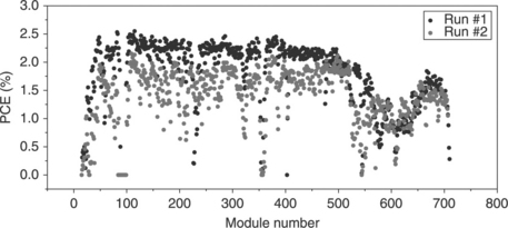
We have constructed a R2R characterization apparatus consisting of a computer-controlled unwinder-rewinder system with a metering wheel to advance modules one at a time under an artificial sun lamp. At this position, electrical contacts are established using a pneumatic system so that one or more IV curves can be measured via a computer-controlled source measure unit (see Fig. 19.7). Automation of the testing procedure through the use of an R2R characterization apparatus is important to match the production speed. Presently, it is possible to measure each PV module in about the same time it takes to produce it (~20 sec). Data are stored for the individual IV scan for each module and also as an overview for the whole roll of modules. These data can be used to identify failed modules due to coating errors and thus serve as a quality control. It is also an important tool for improving the coating process itself. Changes made during the coating of one roll of modules will affect the solar cell parameters that are readily identified by studying e.g. the PCE as a function of module number. R2R characterization coupled to the variation of coating parameters can thus be used as a research tool (Fig. 19.8).
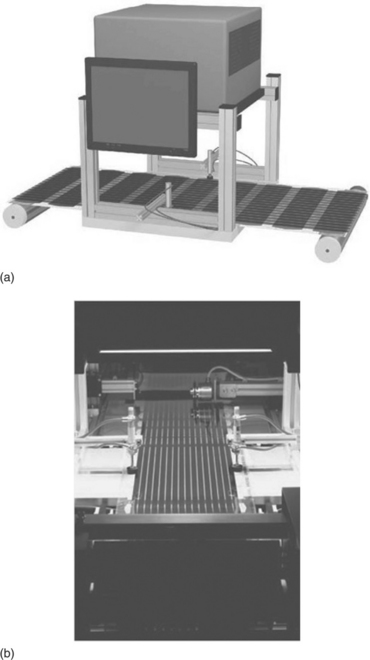
19.7 R2R characterization of R2R-coated photovoltaics shown schematically to the top. A roll of modules comprising stripes of solar cells is advanced one at a time by the unwinder-rewinder system. An artificial sun (large gray box) illuminates the devices while IV scan of the devices is obtained. Electrical contacts to electrodes are established with a pneumatic system (cylinders with tubing). A photograph of the system is shown to the bottom.
Light beam-induced current (LBIC) characterization
Standard testing of a photovoltaic device by measuring the diode characteristics only gives an overall description of its function. Light beam-induced current (LBIC) measurements, on the other hand, map out the current response from individual pixels in the device, and may be used as a tool to study defects and changes in different areas. The measurement can be carried by using a focused light beam (e.g. a laser) mounted on a computer-controlled XY-stage that is scanned in a raster pattern over the area of the device while the current generated is measured. A map can then be constructed from the data as pixels of varying color to represent different levels of current. The LBIC map must then be compared with the image of the device to locate features of interest.
The LBIC technique is well-established for characterizating inorganic solar cells [17] and has also been used occasionally for organic photovoltaics to study degradation, for example [18–20].
As organic solar cells evolve from small-scale laboratory devices with an area of a few square millimeters to larger-scale R2R coated devices and modules, the need to obtain a mapping of the functionality increases for which LBIC measurements seem ideally suited. Larger-scale devices can have defects arising from impurities or coating defects that can be visualized by the LBIC technique. Modules constructed from multiple serially connected solar cells can be mapped to show their individual contribution to the overall device function Fig. 19.9.
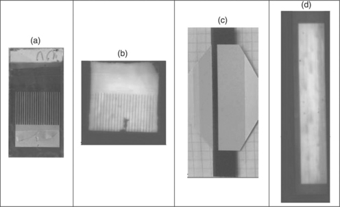
19.9 Example of LBIC maps of a functional map of a P3HT/PCBM-type solar cell with a printed silver back electrode having a grid pattern ((a) and (b)), and a R2R printed solar cell and LBIC map ((c) and (d)), showing small point defects and variations due to the coating process. In the LBIC maps ((b) and (d)), the coloring from blue to yellow represent current from low to high, respectively. The devices are photographed from the back side whereas the LBIC was recorded from the front side.
19.4 Applications and demonstrations of polymer solar cells
19.4.1 Market areas of polymer solar cells
Polymer solar cells perform exactly the same function as any other type of solar cell (the conversion of photons into an electrical current) and will as such enter a well-charted market realm with numerous types of solar cells and numerous possible applications. But the technology is still in development. The present technology’s early stage of maturity, with the recent initial market introduction of low-performing, high-cost, low-lifetime solar cells compared to other types of solar cell, poses a grand challenge. Thus, potential market areas for polymer solar cells have been a topic for much discussion over the past decade among industry, academia and technology competitors. The key observations for this discussion are centered on the performance–cost ratio of an underperforming new technology as it enters a crowded market segment. It is obvious to industry and academic insiders that the premonitions of technology development speed have been overly positive and sent a Klondike-like rush to the heads of many scientists, investors and industry stakeholders – as they all asked the question: ‘what if polymer solar cells actually succeeded in providing the promised potential of very low cost solar energy?’ The determining factors for market application with any solar cell technology are cost, lifetime and PCE – the balance of which here is termed the performance–cost ratio. Some may argue that polymer solar cell technology’s typical features, such as light weight and flexibility, may ease market entry, but this has not yet been established as a fact. Flexibility and light weight possess great functionality in processing polymer solar cells, but in application and product integration especially flexibility seems to have limiting factors, at least at this point in technology development.
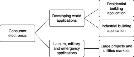
As polymer solar cells were not available in marketable forms until 2009, when Konarka Technologies introduced the first low-performing polymer solar panels [21], numerous application ideas have been formulated and a few of these tested. In perspective, polymer solar cells possess the potential to be applied within consumer electronics, developing world applications, leisure, military and emergency, residential building and industrial building add-on or integration and finally large-scale utility, as illustrated in Fig. 19.10.
The fulfillment of the list of application areas is determined by the continued development in PCE, cost and lifetime and as such indicates that the first market for polymer solar cells will be found to be a power source for small-scale electronic applications, i.e. battery chargers.
In comparison with existing types of solar cells, flexible solar cells (like polymer solar cells) create a number of application possibilities because they are potentially cheap, flexible, lightweight, semi-transparent, variable in color, environmentally friendly and provide portable solar energy. These technology-specific factors, in many ways, represent market opportunities as well as threats. Portable solar energy has been a dream since solar energy was discovered – and, admittedly, possesses interesting possibilities if the solar cell is cheap enough, and if the PCE matches the portable application – which is a key point. External limiting factors are the need for energy and the storage of energy, i.e. the available application and battery capacity coupled with the PCE of the solar cell.
The field of portable electronics today is power-hungry and current portable solar cells cannot power a cell phone, a music player or a laptop – it merely represents a back-up or trickle charge-scale power source and does not provide power ‘on the go’, as many would like it to do. In fact, solar cell being portable does not mean that it can charge the batteries in your gadget while you are on your way to work as this would take a full day or more of direct sun onto the solar cell. Accordingly, a number of disadvantages rest not only with polymer solar cells, but also with adjacent technologies necessary for product integration. The vision for polymer solar cells is power production at low cost. At the present time, the position of polymer solar cells is in between continued technology development and initial market introduction, and consequently affordable power production is far from being within reach. As the technology matures, new applications can be created and new market segments entered. A conservative timeframe estimate for the continued technology development and maturation is represented in Table 19.1. The list represents Risø DTU’s interpretation of the current state of affairs within polymer solar cells indicating that, yes, polymer solar cells represent a significant opportunity, but a stepping-stone approach that allows for learning by doing and slowly evolving technology from its early commercial phase – however exciting as it may be – to the levels of standalone energy production in large volumes, is the path forward for years to come, for the simple reason that it is a complicated technology [2]. When taking a closer look at the early market segments, a few things must be emphasized. Firstly, the quality of the solar cell must be capable of meeting the implementer’s need, i.e. quality, covering such elements as visual performance and general finish, together with general technical performance. Secondly, to sustain revenue, it is central to identify one or more applications that can carry forward the cost of technology development and production, which costs at this early stage are significant. External observers could claim that polymer solar cells, with their apparent superior cost and performance, should be able to outperform all other thin-film solar cells. This would be great if it were so, but polymer solar cells are currently subordinate to all other solar cells in terms of performance and cost. If polymer solar cells were competitive, another point of view could be to try to take over the market of thin-film solar cells. Again issues arise, as it proves that the thin-film solar cell market for small-area charging functions for consumer electronics is quite small [9]. Put differently, thin-film solar cells have not brought forward a portable solar energy revolution and thus, if polymer solar cells intend to do so, the cost–performance ratio should be best in the market and at the same time significant effort should be put into new and innovative application of solar cells. Thirdly, polymer solar cells may be ingenious in their complex simplicity, but it is also through scientific and technological challenge, that offers great challenges when it comes to turning profit in the pre-energy production market – if polymer solar cells cannot meet the challenges in the short-term markets, energy production will remain a dream. For polymer solar cells to compete in a crowded market, significant performance–cost ratio improvements must be made. This poses a significant economic challenge that can only be met by external capital and public funding, unless industry itself, by skilled technological development, is capable of turning below-par solar cells into revenue via uncharted market segments [2,9].
Table 19.1
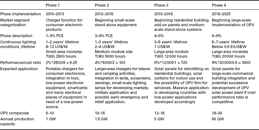
Note: Phase projection development scenario was compiled from industry and academic conference presentations and discussions over the course of 2008–2010. As the performance/cost ratio of the solar cell develops, new market segments will become available. The applied time frame is an estimate of when each of the phases will begin – the overlap is intentional. Cost is indicated for large-area module for phases 3 and 4. Annual capacity is capacity and not amount of manufactured cells.
Polymer solar cell-producing energy raises the question of competition, especially with silicon solar cells. One point of view is that all the solar cells that can be produced can be installed, as demand is immense. If so, polymer solar cells should not be seen as a competitor to or substitute for silicon solar cells, but rather as an alternative for specific applications over the next 10 to 20 years.
19.4.2 Adaptable small-volume applications
The flexibility and reasonably light weight of polymer solar cells provide much, promise and create many applications, among which examples like the polymer solar-clad blimp, solar textile and sports equipment like footballs covered with solar cells and fitted with electronics that report back on speed, height, position and maybe air pressure are among the more challenging [22,23]. However, it is flexibility in terms of processing a polymer solar cell in any shape needed that may become the primary functionality of this type of solar cell, if, the right application becomes available. The application of screen printing and flexographic printing allows for the patterning of designed shapes that again allow for unique solar cells to be prepared for any type of application [5]. If, for example, a company were in need of a solar cell sticker for a toy car or for the roof of a toy house, the printing process allows for individual design – so that design flexibility becomes a widespread factor in applying solar cells. An example of this was the Risø DTU solar cell demonstration in a hat containing a radio. The design of the solar hat made it necessary to have a round solar cell instead of the standard rectangle used in any type of solar cell product.
Figure 19.11 shows the resulting solar cell design, and as such provides the promise of potentially any shape needed. Bringing this technological ability forward allows for numerous product ideas to be generated. As such, polymer solar cell technology represents a previously unseen adaptability to intended applications and will, if designers learn to work with the technology, present a number of interesting application opportunities.
19.4.3 Large-volume applications – aims and limitations
The ambition of polymer solar cells is to provide affordable solar energy at a cost below 0.5€/W. This ambition is based primarily in the cost potential that lies in the application of inexpensive materials and simple manufacturing equipment with a low thermal budget, which carries low investment cost and is easily scalable.
For this ambition to have any basis to grows polymer solar cell technology must mature significantly and a vigorous testing scheme must be established for outdoor polymer solar cell panels as to understand better the issues related to degradation in order to improve lifetime significantly. Key technology developers like Konarka and Risø DTU are both engaged in outdoor testing of polymer solar cells. In April 2009, Risø DTU demonstrated a panel-scale outdoor solar testing unit for the long-term weathering effect on polymer solar cells. The applied solar tracker (AZ-225 Dual Axis, Azimuth Drive Solar Tracker) was fitted with polymer solar cell panels manufactured in collaboration with Danish silicon solar panel manufacturer Gaia Solar A/S. The three installed panels each measured 1 × 1.7 meters and were fitted with 24 solar-cell modules, each 20 × 25 cm. Power production from each panel was 11 W, of which 7 W were fed into the electrical grid, and as such these became the world’s first grid-connected polymer solar panels (Fig. 19.12).
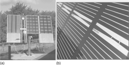
19.12 (a) Photographs of a solar tracker with mounted polymer solar cell panels comprising different sizes of the individual polymer solar cell modules connected to give the same panel size (1.0 × 1.7 m2). (b) A close-up photograph of the panel showing individual polymer solar cell modules.
By May 2010, third-generation polymer solar cell modules were installed and are now in daily operation. The key objective of this demonstration was to understand the long-term weathering effect on large-area polymer solar cell panels in collaboration with industry [24]. Current limiting issues with polymer solar cells with regards to energy-scale production are obviously the weak performance–cost ratio. A comparison with silicon solar cells will show that their lifetime is too short, that their PCE is too low, and that their cost is factors away from being relevant to any use resembling commercial energy production. Academia agrees that, although the lifetime of polymer solar cells is unlikely to rival that of silicon solar cells, lifetimes of 8–15 years may be within reach, that their PCE should, without too many issues, be able to reach 10–15% and that cost below the level of 0.5 €/W in large-scale production may become possible. Of these three, the determining factor will be the reduction of cost through large-scale production and novel panel manufacturing methods to take advantage of the technology features, if polymer solar cells in any way intend to contribute to the global energy production.
19.4.4 Recent demonstrations
For polymer solar cells, demonstration is a tool to create awareness of the technology outside academic circles in order to spark interest among designers, potential manufacturers and end-users, who all help to motivate the development of technology’s implementation. Demonstrated polymer solar cells have proven to be a very good indicator of the maturity level of the technology. One may say what one can do, but if one cannot show what one can do, the value of what was said may be questionable. Thus a polymer solar cell that is integrated in a given product and that able to power product for its intended lifetime is a very strong indicator of the technology’s capability – under the notion that anyone in a competitive technology development race is interested in attracting attention on the premises of what they are able to provide. For example, if it were possible to manufacture polymer solar cells at low cost, and with reasonable efficiency and lifetime, the product would already be on the market, but this is not so – as available polymer solar cells are short-lived, inefficient and expensive compared to other types of solar cell.
Konarka Technologies and Risø DTU are both strong proponents of demonstration. Beyond the extent to which it provides very good PR, as a significant learning process is associated with the generation of polymer solar cell application, the consecutive realization of the solar cells, product design and integration and the testing of the product in real life. In other words, demonstration projects stand as a market introduction exercise for an unproven technology.
Konarka Technologies provided a large-scale demonstration in San Francisco in 2009, where the solar-powered bus shed rooftop was introduced with the intent to install 1100 over the next few years. Local partners were 3Form, Lundberg Design and Clear Channel Outdoor, who together with Konarka designed the wave-shaped polycarbonate structure [25]. There is no available information on lifetime or PCE regarding the installation, but a reasonable performance–cost ratio must be expected, as the total demonstration totals between 75 000–100 000 polymer solar panels. Another Konarka demonstration, which is now commercially available, is the shoulder solar bag. It serves as a marketing function and it seems to be the first integrated polymer solar cell product on the market – again, clearly indicating the maturity and performance level of polymer solar cells.
At Risø DTU, the demonstration of technology is used as an integrated technology development tool that allows the generation of knowledge about the full value chain from the point where a polymer solar cell product application idea is presented to the final, applicable and tested product. As the first in the world, Risø DTU demonstrated industrially manufactured polymer solar cells on the scale of thousands in collaboration with Mekoprint A/S, a Danish printed electronics manufacturer. By screen printing, a round solar cell was manufactured and integrated in a solar hat, where it charged a small AAA-battery powering a small radio. The solar hat product was first introduced and tested at the Roskilde Festival in 2008 [10] (Fig. 19.13).

19.13 A photograph of the solar hat comprising sun hat, polymer solar cells and integrated radio. Demonstrated at the Roskilde Music Festival in 2008.
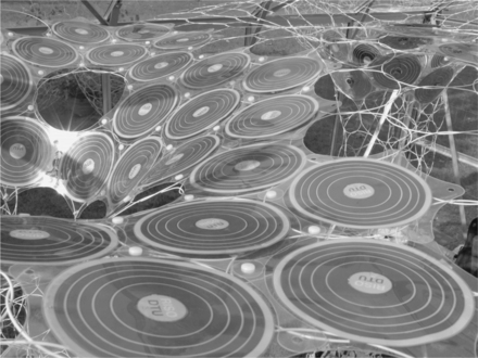
A second demonstration was the Suntiles solar curtain in collaboration with Astrid Krogh Design (Fig. 19.14). The ‘Suntiles’ curtain was made from polymer solar cells modules, or tiles – thus the name ‘Suntiles’ – and applied the power-producing capability and lightweight character of the polymer solar panels to create a mobile-like hanging power-producing sun-shading structure. The Suntiles curtain was made from 90 tiles and was exhibited at the Danish Design Center in Copenhagen in May 2009 [26].
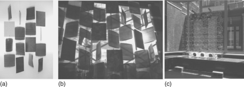
19.14 Photographs of Suntiles. (a) A small demonstration comprising solar cells and phase change materials. (b) The 3 × 4 m2 window panel that was demonstrated as part of the international exhibition ‘it’s a small world’ 2009–2010. (c) A window exhibition in New York. (courtesy of Loop.PH)
A third large-scale demonstration was the development of the Lighting Africa polymer solar cell-powered light-emitting diode (LED)-based lamp (Fig. 19.15), which demonstrated polymer solar cells as a power source for lighting purposes in rural communities in developing countries. The Risø solar lamp project was inspired by the World Bank initiative named Lighting Africa (www.LightingAfrica.org, with the ambition of limiting the use of kerosene and oil lamps by introduction of solar-powered lighting products) and was first established as a reading lamp for school children. The potential lies in the possibility of creating affordable LED-based lamps that meet the need of the user in the user habitat and which can replace the widespread use of kerosene lamps – including a global fuel market of US$ 38 billion. Polymer solar cells may possess the necessary performance–cost ratio for providing affordable solar lamps.
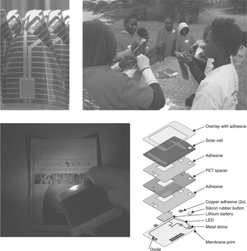
19.15 Lighting Africa lamps from field testing in Zambia (2009) (top) and a small pocket-sized torch prepared by fully automated processing (bottom).
The demonstration of polymer solar-powered LED lamps continues and an improved version of the Lighting Africa lamp was ready for testing by the end of 2010 [27,28]. For the development of polymer solar cell technology, demonstration projects will play a significant role in its further market introduction as ideas are turned into demonstrations that are made into products, so that end-users learn what the technology is capable of. Polymer solor cells will mature only through step-by-step, persistent doing and learning and if there is sufficient participation in the effort to make solar energy affordable to the masses.
19.5 Conclusions and future trends
To conclude, it is clear by now that polymer solar cells have a commercial potential of which the extent is largely unknown at present. They are likely to also play a role in future electrical energy production if we project the progress between 1990 and 2010 into the next decade. There are, however, still massive challenges to overcome before polymer solar cells can be envisaged to contribute significantly towards global electrical energy production, but in contrast to many of the thin-film solar cell technologies, the positive message is that there is no evidence that this is impossible. This is the case for many of the novel thin-film technologies that have great commercial potential, but if one extrapolates to a commercial scale, elements such as tellurium and gallium simply do not exist in the abundance needed for the technology to be viewed as realistic. The pursuit of future versions of the polymer solar cell that reach the low-cost potential of the technology will present indium-free, vacuum-free ambient processing without the use of materials with high embedded energy, low-cost encapsulation schemes and fast manufacture.
19.6 Acknowledgements
This work was supported by the Danish Strategic Research Council (DSF 2104-05-0052 and 2104-07-0022), EUDP (j. nr. 64009-0050) and PV ERA-NET transnational POLYMOL project PolyStaR.
19.7 References
1. Helgesen, M., Søndergaard, R., Krebs, F.C. Advanced materials and processes for polymer solar cell devices. Journal of Material Chemicals. 2010; 20:36–60.
2. Nielsen, T.D., Cruickshank, C., Foged, S., Thorsen, J., Krebs, F.C. Business, market and intellectual property analysis of polymer solar cells. Solar Energy Materials and Solar Cells. 2010; 94:1553–1571.
3. Dennler, G., Scharber, M.C., Brabec, C.J. Polymer-fullerene bulk-heterojunction solar cells. Advanced Materials. 2009; 21:1323–1338.
4. Gonzalez-Valls, I., Lira-Cantu, M. Vertically-aligned nanostructures of ZnO for excitonic solar cells: a review. Energy and Environmental Science. 2009; 2:19–34.
5. Krebs, F.C. Fabrication and processing of polymer solar cells. A review of printing and coating techniques. Solar Energy Materials and Solar Cells. 2009; 93:394–412.
6. Soga T., ed. Nanostructured materials for solar energy conversion. UK: Elsevier, 2006.
7. Krebs F.C., ed. Polymer photovoltaics: a practical approach. Bellingham: SPIE Press, 2008.
8. Brabec C.J., Scherf U., Dyakonov V., eds. Organic photovoltaics: materials, device physics and manufacturing technologies. Weinheim: Wiley–VCH, 2008.
9. Krebs F.C., ed. Polymeric solar cells: materials, design, manufacture. USA: DEStech Publications Inc., 2010.
10. Krebs, F.C., Jørgensen, M., Norrman, K., Hagemann, O., Alstrup, J. A complete process for production of flexible large area polymer solar cells entirely using screen printing—first public demonstration. Solar Energy Materials and Solar Cells. 2009; 93:422–441.
11. Krebs, F.C., Gevorgyan, S.A., Alstrup, J. A roll-to-roll process to flexible polymer solar cells: model studies, manufacture and operational stability studies. Journal of Material Chemistry. 2009; 19:5442–5451.
12. Krebs, F.C. All solution roll-to-roll processed polymer solar cells free from indium-tin-oxide and vacuum coating steps. Organic Electronics. 2009; 10:761–768.
13. Krebs, F.C., Tromholt, T., Jørgensen, M. Upscaling of polymer solar cell fabrication using full roll-to-roll processing. Nanoscale. 2010; 2:878–886.
14. Krebs, F.C. Polymer solar cell modules prepared using roll-to-roll methods: knife-over-edge coating, slot-die coating and screen printing. Solar Energy Materials and Solar Cells. 2009; 93:465–475.
15. Krebs, F.C., Norrman, K. Using light induced thermocleavage in a roll-to-roll process for polymer solar cells. ACS Applied Material Interfaces. 2010; 2:877–887.
16. Strange, M., Plackett, D., Kaasgaard, M., Krebs, F.C. Biodegradable polymer solar cells. Solar Energy Materials and Solar Cells. 2008; 92:805–813.
17. Boyeaux, J.P., Laugier, A. Journal de Physique, Colloque 1989; [(C6, Beam Injection Assess Defects Semicond), C6-111/C6-127 (review).].
18. Sirimanne, P.M., Jeranko, T., Bogdanoff, P., Fiechter, S., Tributsch, H. On the photo-degradation of dye sensitized solid-state TiO2 |dye|CuI cells. Semiconductor Science and Technology. 2003; 18:708–712.
19. Cataldo, S., Fabiano, S., Ferrante, F., Previti, F., Patané, S., Pignataro, B. Organoboron polymers for photovoltaic bulk heterojunctions. Macromolecular Rapid Communication. 2010; 31:1281–1286.
20. Bull, T.A., Pingree, L.S.C., Jenekhe, S.A., Ginger, D.S., Luscombe, C.K. The role of mesoscopic PCBM crystallites in solvent vapor annealed copolymer solar cells. ACS Nano. 2009; 3:627–636.
21. www.konarka.com (accessed on 26 August 2010).
24. Medford, A.J., Lilliedal, M.R., Jørgensen, M., Aarø, D., Pakalski, H., Grid-connected polymer solar panels: initial considerations of cost, lifetime, and practicality. Solar Energy Materials and Solar Cells 2010; . http://dx.doi.org/10.1016/j.solmat.2010.06.007
25. Bus stops by Lundberg Design and 3Form generate power for San Francisco, Interior Design, http://www.interiordesign.net/article/ca6678576.html (accessed on 26 August 2010).
26. http://www.astridkrogh.com/html/suntiles.html (accessed on 26 August 2010).
27. Krebs, F.C., Nielsen, T.D., Fyenbo, J., Wadstrøm, M., Pedersen, M.S. Manufacture, integration and demonstration of polymer solar cells in a lamp for the ‘Lighting Africa’ initiative. Energy and Environmental Science. 2010; 3:512–525.
28. Krebs, F.C., Fyenbo, J., Jørgensen, M. Product integration of compact roll-to-roll processed polymer solar cell modules: methods and manufacture using flexographic printing, slot-die coating and rotary screen printing. Journal of Material Chemistry. 2010; 20:8994–9001.